Week 1: Recitation Documentation – Young
Recitation 1: Electronics and Soldering
Instructor: Young
Partner: Kaycee Chen
Materials Used in Circuits:
- Breadboard – a device used for carrying and connecting different materials
- LM7805 Voltage Regulator – the components used to maintain voltage output
- Buzzer – the out put, beep when working
- Push-Button Switch – the device used to control the current
- Arcade Button – another device used to control electrical flow through the circuit
- 220 ohm Resistor – used to limi the voltage that flows in the circuit
- LED – out put, light up when electricity flows through
- 100 nF (0.1uF) Capacitor – used to protect the circuit
- 10K ohm Variable Resistor (Potentiometer) – used to control the voltage that flows to the LED so as to control the brightness of the LED
- 12 volt power supply – supply the circuit
- Multimeter – can be used to test different information of different components
- Several Jumper Cables (Hook-up Wires) –used to connect different components
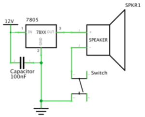
Circuit 1: Lamp
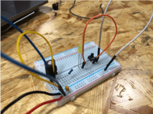
Components used: Breadboard, LM7805 Voltage Regulator, Buzzer, Push Button Switch/Arcade Button, 100 nF (0.1uF) Capacitor, 12 volt power supply, Barrel Jack
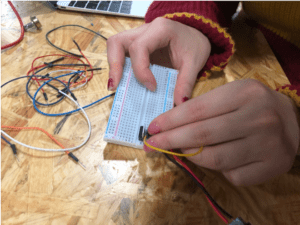
This small model is the first project that I have ever completed. Though it is very simple, it helps me to get to know about how do different components works together and function properly. Our group actually met with several obstacles at first, the LED didn’t light up after several attempts. After turn to Instructor Young for help, he examine all the components one by one and told us there is something wrong with the breadboard. So we changed a new breadboard and eventually saw the light given out from the LED. The second time we rearrange our jumper cables in a more organized way because Instructor Young told us it will be easier to debug in this way and we finished it much faster than we did it the first time.
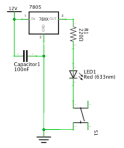
Circuit 2: Door Bell
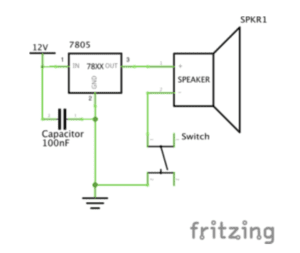
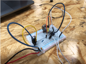
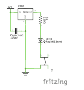
Components used: Breadboard, LM7805 Voltage Regulator, Buzzer, Push-Button Switch/Arcade Button, 100 nF (0.1uF) Capacitor, 12 volt power supply, Barrel Jack, 220 ohm Resistor, LED
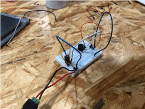
With the experience of the first circuit assembling, my partner and I made the second circuit much faster. However, the Buzzer didn’t beep no matter how we test it. We turn to Instructor Young again and after checking our circuit he told us to pay attention to the direction of the switch. We found it very tricky but there is still tiny difference in it so we rearrange it and succeeded.
Circuit 3: Dimmable Lamp
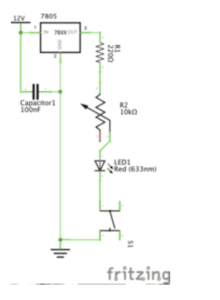
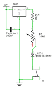
Components used: Breadboard, LM7805 Voltage Regulator, Buzzer, Push-Button Switch/Arcade Button, 100 nF (0.1uF) Capacitor, 12 volt power supply, Barrel Jack, 10K ohm Variable Resistor (Potentiometer), LED
After succeeded twice, we finished this one quickly and successfully. It is really proud to see the brightness of the LED being manipulated by us.
Since I have experience of connecting jumper cable in a competition I took part in during my high school, it wasn’t a difficulty for me. I finished efficiently and helped my partner.
Question 1:
The Lamp light up, the buzzer beeps, the brightness of the LED changed when we press the button or turn the Variable Resistor. It is a kind of interaction between the circuit that we built and us.
Question 2:
I think more controllable components or sensors that will respond to motion, heat etc. can be used to create the interaction Design and Physical Computing because interaction means the project must interact with human beings so these components are very necessary to a successful Interaction art.


