Week 2 recitation- Santiago Salem

Partner: Sarah Waxman

Circuit 1: Fade

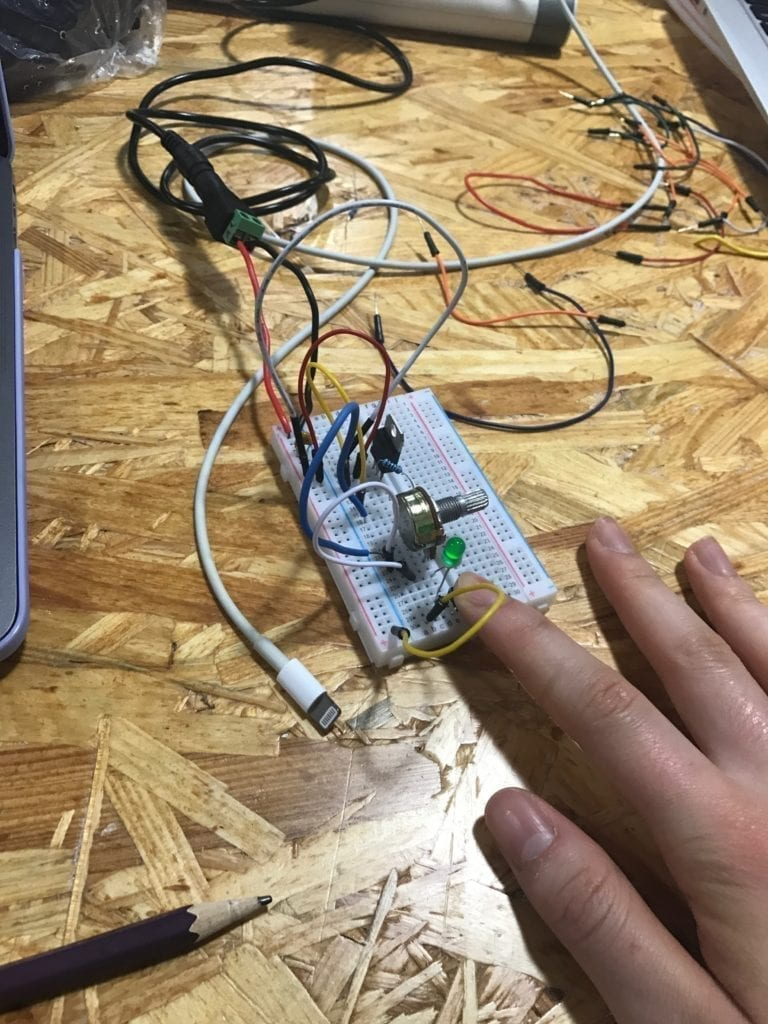
The first circuit was really easy to assemble. We already had the code that fades the LED light on the Arduino app on our computer. The components for this circuit where minimum, just two cables, 1 resistor, and the LED ( and obviously a computer and the Arduino). We encounter no problems building this circuit .

Circuit 2: Tone Melody

Circuit 2 was similar to circuit one, only that this time instead of making the LED fade we had to make a sound from the buzzer. Once again the required material for this circuit where minimum. We used a buzzer a resistor and two cables (Arduino and Computer). The code was simple and it was already saved on the Arduino app on our computers, all we had to was run it. The sound this buzzer emitted had a delay like every second which later became really annoying after a couple of minutes. 

Circuit 3; Game

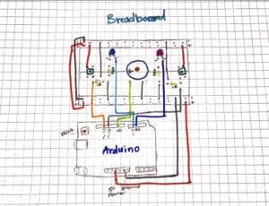
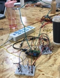
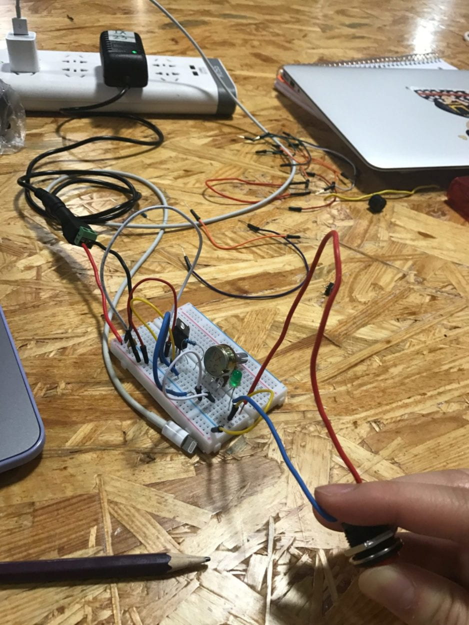
Oh, this circuit was nothing compared like the two previous ones. In order to assemble circuit 3 we needed to mix our knowledge of circuit one and two.  We had to construct a game were one player had to click the button more times than the other player (in order to win). Every time a player clicked  a button the buzzer emitted a sound, and at the end of the game one of the LED lights( on opposite sides)  lighted up indicating the winner. The instructions to build this circuit were very clear and concise, therefore we where able to assemble it quickly. But that was our first mistake, we made it so quick that we forgot how some of the components are polarized ( so you have ti put them in a certain location and position). The second problem was that we   had a short circuit, meaning that the usb in the computer didn’t allow the connection due to the overflow of electricity that came from the Arduino. After fixing the short circuit we finally where able to play the game. The code for the game we got it from an online source (https://www.tinkercad.com/things/6MzvN5rlZlr-race-the-led-spring19. ) that we copy and paste on our Arduino app on our computers. 

Question 1

Is almost impossible to live in todays world without having to interact with technology. Every day people and computers are coming closer to each other, meaning that computers are responding to almost every human sense they detect( known as physical computing). This type of technology is among almost every technological device we use. For example the circuits we build during this recitation (as simple as they might look)  where able to respond to our touch,  For example: circuit 3 was depending on our touch in order to run the game.  Not only this is a perfect example of physical computing, but also of how humans always pursue a closer interaction with technology. Is a codependent relation, meaning that we need technology to advance and technology needs us in order to improve (and work) .  Technology is a source that humans can alter and manipulate to their own purposes. Its a source thats is always available to help and entretain humans. 

Question 2

If I had a 100,000 led lights I would put them all under a pool made of glass. So, when the led lights detects motion they light up and follow the swimmer. This will help safeguards detect people easier and it could also be a beautiful show.
Recitation 2: Arduino by Citlaly

First Circuit

  • Breadboard to Arduino
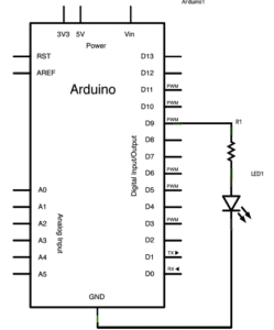
    • First, we attached the resistor to D9 output on the Arduino. Then the LED to the resistor and from the LED connected that to the ground of the Arduino.
  • Code
    • On the Arduino software, we followed the directions of Arduino>File>Examples>03.Analog>Fading and successfully got the light to fade!

IMG_8278.TRIM

Second Circut

  • Beadboard to Arduino
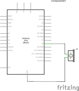
    • We simply attached the speaker to D8 output on the Arduino and attached it to the ground of the Arduino.
  • Code
    • We followed the Code: Arduino>File>Examples>02.Digital>toneMelody; however, we were having an error message and it turned out we did not have the code set up with the right port of the Arduino. 

IMG_8279

Third Circuit

  • Breadboard to Arduino
    • On www.tinkercad.com we found the circuit. After connecting the ground and power of the breadboard to the ground and power to the Arduino, and also connecting the power and ground of both sides of the breadboard. My partner and I started from the outside in (each having our own side)of the circuit. First, we connected the button and connected that to power on the breadboard. Then we connected the button to the 10 resistor and connecting that resistor to ground on the breadboard. Then starting with the positive side of the  LED into #2 output on the Arduino and the negative to the 220 resistor, but it was wrong so we switched it connecting the negative side to the #2 output and the positive to the 220 resistor.  Then connecting the 220 resistor to ground on the breadboard we finally came to the end connecting the speaker in the middle while also connecting the positive side to #8 output on the Arduino and the negative side to ground on the breadboard.
  • Code
    • The code we simply copied from www.tinkercad.com and it ran after a check on all the wires connections.

IMG_8281

Fourth Circut 

Here we ran out of time, but we experimented attaching a second breadboard to another and have them share one Arduino. All we finished was the attaching since time was spent in trying to find long enough wires leaving us never finding out if our master pice worked.

Question One:

Reflect how you use technology in your daily life and on the circuits you just built. Use the text Physical Computing and your own observations to define interaction.

Answer One:

My daily life is consumed by technology because as it grows the more it is used to complete assignments and used for entertainment. Much of the input and output of any of my technology, laptop or phone, is done for me. All I do is either type or click and I trigger an already programmed processing. The circuit is different, this time I am the one putting together the output and eventually need to find the correct input for whatever I am trying to make. This interaction is more of a higher degree of interaction because of the hands-on work to create the output, not knowing whether the processing will be a success, rather than using an already made input and output knowing the processing will be a success.  There is more conversation that goes into making than using.

Question two:

If you have 100,000 LEDs of any brightness and color at your disposal, what would you make and where would you put it?

Answer two:

I would want to make a covered slide where it is dark on the outside, but once inside it is lit up by a rainbow of colors at a not too bright setting that it hurts the eyes (make the brightness adjustable). I would want to take this to the DuPont Hospital for Children that is local to me where I volunteered back in Pennsylvania. I would want to make it safe for kids with any disability to be able to use it, but most importantly something fun for the kids. There could be different themes too like underwater or rainforest and put audio in to make their situation transform.

IL(Young) – Recitation1: Electronics & Soldering, Olivia Zhou

Materials and functions:

  • 1 * Breadboard      Provide a base for making electronic connections and aid in the prototyping of circuits.
  • 1 * LM7805 Voltage Regulator    Maintain a constant voltage level. Make the output voltage 5V for other components to work safely.
  • 1 * Buzzer      An audio signaling device.We can tell if the circuit works by listening to it.
  • 1 * Push-Button Switch      Be used to interrupt the flow of current through a circuit. We use it to control(turn on/off) the buzz and the LED.
  • 1 * Arcade Button     Be used to interrupt the flow of current through a circuit. We use it in soldering. Actually it’s an alternative of push-button switch.
  • 1 * 220 ohm Resistor      Resist the flow of electricity to control the flow of current. It protects the LED from burning out.
  • 1 * LED      A visible light source. We can tell if the circuit works by looking at it.
  • 1 * 100 nF (0.1uF) Capacitor      Store electricity while current is flowing into them, then release the energy when the incoming current is removed. (Question: I still don’t know why it is included in circuits and in parallel with other loads)
  • 1 * 10K ohm Variable Resistor (Potentiometer)      A resistor whose resistance can be adjusted. We use it to change the degree of LED brightness.
  • 1 * 12 volt power supply      Provide the power for other components to work. It( 12V DC) was translated from 220V AC and then to 5V DC.
  • 1 * Barrel Jack      It connects the power supply with the breadboard.
  • 1 * Multimeter      Be able to measure the electrical properties of voltage, current and resistance. They are useful for testing circuits and determine the cause of electrical problems within a circuit. We use it to measure the resistance to find a 220 ohm resistor out of others.
  • Several Jumper Cables (Hook-up Wires)      Be used to carry electricity from one point to another. We use it to connect different electrical components.

Tasks

  • Circuit 1

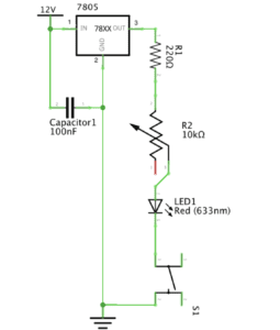
diagram

Picture of Door Bell

video

process    

 Actually, this was my first time to build a circuit, although I had previewed some readings, I still got confused at first. So did my partner Sarah. So she asked a teaching fellow for help. The fellow almost helped us through the whole course. The first problem we confronted is about  the resistors . We measured several resistors with the multimeter. But their resistance were all 10 ohm. At last we found one 220- ohm resistor with the help of the fellow.

  • Circuit 2

diagram

video

process

In this task, we added a new component: switch. But after we finished building the circuit and pressed the button on the switch, it didn’t work because the LED was always on. With the help of the teaching fellow we found out that we actually put the switch in the wrong place, so it was always connected. Later we put it across the middle line of the breadboard. 

  • Circuit 3

diagram

video

process

We built this circuit quite successfully and smoothly, just by adding a potentiometer on the basis of task two.

  • Soldering

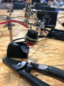
picture

process

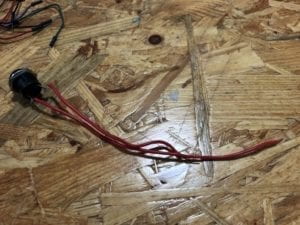
My partner Sarah tried to solder the Arcade Button with the red electric wire first, and the teaching fellow( another) emphasized that we should use the side of the tip of the iron instead of the very tip and scratch the soldering iron in the box when that part turns dim. But when I tired to solder the Arcade Button with the black electric wire, it still turned to be difficult to feed the melting roll of solder into the contact point. Anyway, I made it.

Answers to questions:

 1. In “The Art of Interactive Design”, the author generalizes the notion of the conversation as an interactive process to any human interaction and condensed it to three steps: listen, think, and speak (in turn). Academically, it’s input, process and output. From my perspective, the circuits we built do include interactivity because they can respond to our deeds like clicking the button of switch and changing the resistance of potentiometer by turning on and off the buzz/LED and changing the degree of LED brightness. But it’s also of low interactivity like the example of refrigerator light given by the author.

2. In Zach Lieberman’s video, the most impressive project for me is EyeWriter designed for paralyzed graffiti writer Tony. Their team created low-cost eye-tracking softwares and hardwares( connecting IR LEDs, micro CCD CAM, etc to sunglasses with copper wires and wire ties ), the result was quite pleasant that Tony could write graffiti and polish his works with his eyeballs, and his graffiti was even shadowed to the building.In my opinion, Interaction Design is the inner inspiration and Physical Computing is the technical basis for the design to be operated successfully. Interactive Art is created by the combination of the two.

Reference list:

Class 02 / Feb 14 Thu / Electricity, Electrical Components & Circuits

The Art of Interactive Design

Zach Lieberman’s video

IxLab (Young) – Recitation 1: Electronics & Soldering – Ivy

Recitation 1: Electronics & Soldering 

February 15th, 2019

Objectives: 

  • Learn the basics of circuits by building three circuits
  • Learn how to solder

Materials:

  • 1 * Breadboard : a solderless device for circuit design
  • 1 * LM7805 Voltage Regulator: converts to 5v and maintain the voltage level to be used by the buzzer
  • 1 * Buzzer: creates a sound when connected to power
  • 1 * Push-Button Switch: turns on and off to control electricity flow
  • 1 * Arcade Button: same function as the switch (we solder a button in this lab) 
  • 1 * 220 ohm Resistor: an electronic component that adjusts the resistance of electricity and controls the flow of current to be used for the LED light
  • 1 * LED: a type of diode as a light source
  • 1 * 100 nF (0.1uF) Capacitor: an electronic component that stores electrical energy when the circuit is connected to power
  • 1 * 10K ohm Variable Resistor (Potentiometer): adjusts the level of resistance to allow more or less voltage through
  • 1 * 12 volt power supply: supplies power for the circuit
  • 1 * Barrel Jack: connect power
  • 1 * Multimeter: used to measure electrical properties like voltage, current and resistance 
  • Several Jumper Cables (Hook-up Wires): connects components of a circuit together

Exercise:

Partner: Robin Luo

Solder an Arcard Button

At the station, we soldered wires onto an arcade button using Tin. It was a challenging process melting the Tin and putting it at the right place. When we used the button in our circuits later on, we realized that it is better to use two different colored wires to distinguish input and output. We also encountered a problem with the button which will be discussed in detail in circuit 2. 

Circuit 1: Door Bell

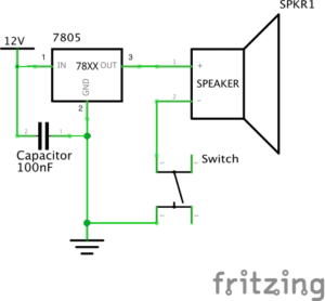
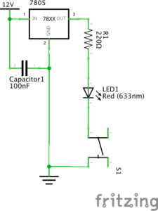
circuit 1 schematics 

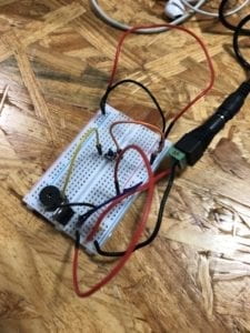
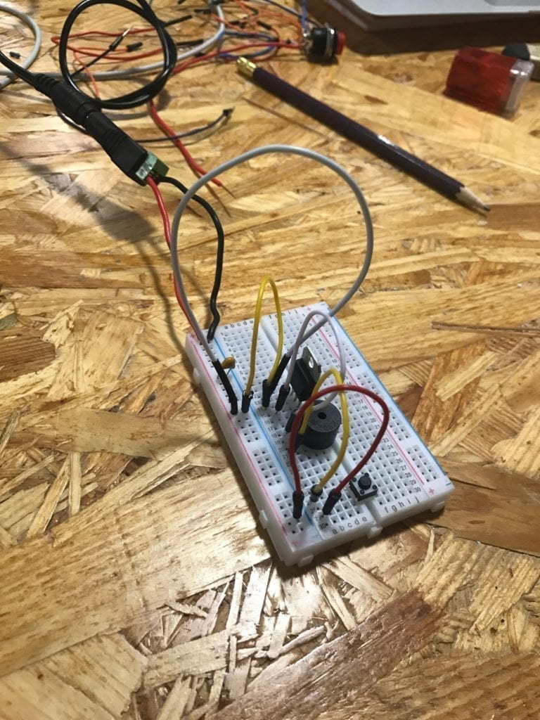
My partner and I did a lot of trial and error for the first circuit. We were confused about general practices like how the breadboard works, where to put the capacitor, the orientation of the voltage regulator. The first time we assemble the circuit, the buzzer did not ring. After talking to some fellows and “debugging the circuit”, we noticed two problems 1) the capacitor was misplaced and we had extra wires connecting to and from it 2) we got the orientation of the voltage regulator wrong. To fix these problems, we placed the capacitor next to the power supply from power to ground and got rid of any extra wires. We also rotated the voltage regulator. 

The working circuit: 

Circuit 2: Lamp

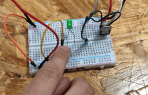
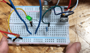
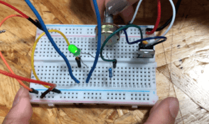
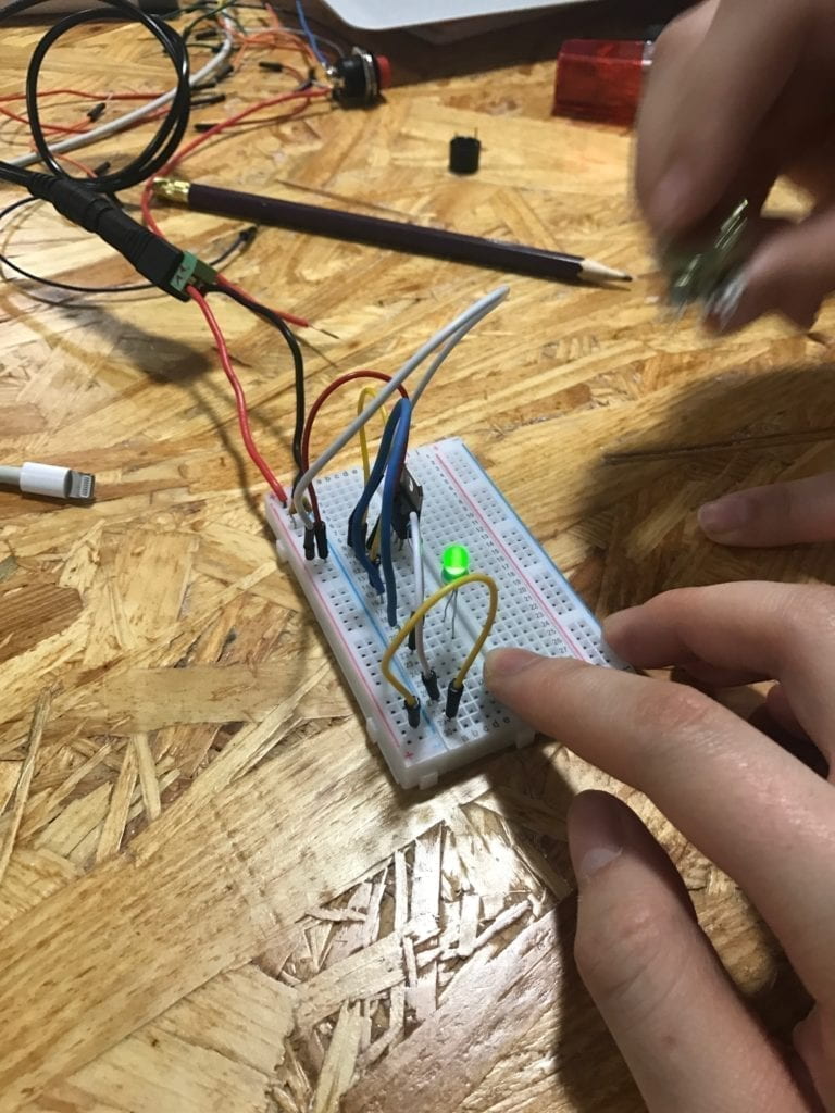
With experience from building the first circuit, we were more time efficient with the second one. Because we are given two resistors with different Ohms, we used the multimeter to find out the 220 Ohm one. Then we connected the resistor to the led and the circuit worked without a problem. 

The working circuit:

Area for improvement: the wires for this circuit are quite messy, it would be better to rearrange and clean up them. 

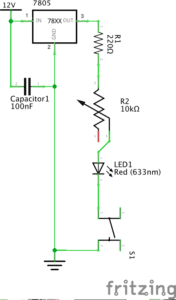
Circuit 3: Dimmable Lamp 

We also did not have much trouble with assembling the third circuit. It was very similar to the second one except with the addition of a variable resistor to control the level of resistance and thus LED brightness. 

Working circuit:

Switch the switches

For each of the circuits, we tried with both push-down button and the arcade button. We had an issue with the arcade button we soldered ourselves. The circuit would only work for the push-down button but not the arcade one. After consulting with a fellow, we used the multimeter to test if the button is working. It turns out that we might have accidentally bent the wire too much while soldering and that cuts down the current flow. When given a new working arcade button, our circuit worked again. 

Questions:

Question 1:

After reading The Art of Interactive Design, in what way do you think that the circuits you built today include interactivity? Please explain your answer.

Interactivity can be a subjective term and should be treated on a relative, continuous scale instead of as a boolean value. The process of building the circuits was quite interactive to me as I got to experiment, make mistakes and eventually assembled them successfully. However, as circuits with only a button and an additional variable resistor for circuit 3, the pure degree of interactivity is quite low. Even though we were able to hear sound or see light, the interactivity of these circuits is comparable to that of the fridge example discussed in the chapter. 

Question 2:

How can Interaction Design and Physical Computing be used to create Interactive Art? You can reference Zack Lieberman’s video or any other artist that you know .

Physical computing provides the software and hardware required to build interactive systems. And interaction design allows these systems to be created, altered and fitted for expressing specific ideas and evoking desirable behaviors and actions. Together they enable the creation of interactive art from the technical and artistical aspects as well as the sensory experience. The example mentioned by Zack Lieberman on eye tracking system for drawing is a perfect blend.  As physical computing made eye-tracking possible, Zack and his team also had to design the interaction for disabled artists. The two parts go hand in hand to create Interactive Art. 

Week 1: Recitation Documentation – Jennifer Cheung (Young)

For our first recitation, our task was to build three circuits with basic knowledge of how breadboards, resistors, and LEDs work. To build them, we used:

  • 1 Breadboard
  • 1 LM7805 Voltage Regulator
  • 1 Buzzer
  • 1 Push-Button Switch
  • 1 Arcade Button
  • 1 220 ohm Resistor
  • 1 LED
  • 1 100 nF (0.1uF) Capacitor
  • 1 10K ohm Variable Resistor (Potentiometer)
  • 1 12 volt power supply
  • 1 Barrel Jack
  • 1 Multimeter
  • Several Jumper Cables (Hook-up Wires)

Circuit 1

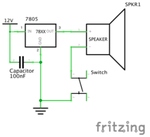
My partner and I, having no prior experience with hardware, went into making the first circuit a bit blind. We were confused about how the circuit map translated onto the breadboard, which I thought would physically be a similar layout as seen in the image. However, Katie came over to help us have a clear idea of how to read the circuit map. She explained that the breadboard would look much different than the picture, and that the picture was only a guide of how to connect the elements with the cables. She told us to start at the 12V power, where we should plug in power and ground into the side of the breadboard. Then working our way outwards, we connected the voltage regulator that maintains a constant voltage level to the speaker which emits a high pitched sound. Katie gave us a hint of how to place the switch that triggers the speaker over the gap in the middle of the breadboard, and to put the capacitor that stores electrical energy in between the power and voltage regulator. Once plugged into power, we pressed the switch and heard the high pitch from the speaker, indicating success! Circuit 1

Circuit 2

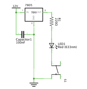
After getting the rundown from Katie of how to read the circuit map and build onto the breadboard, constructing the second circuit was a lot simpler. Most of the positioning on the breadboard was similar to Circuit 1, but instead of the speaker, we added in the resistor that reduced current flow and the LED light, paying attention to the LED’s polarity. When we pressed the switch, the LED lit up, making it another successful circuit. Circuit 2

Circuit 3

We gained confidence for the last circuit, since it only required adding a variable resistor to dim the LED on Circuit 2. However, we ran into trouble with reading the circuit map, since the symbol included an unconnected arrow. We fumbled around with trying to connect the variable resistor, unsure of where the connections needed to go. Katie helped us read the map and figure out that one of the three prongs on the resistor didn’t need a connection. Nevertheless, it was still a bit hard making sense of the wire-ridden board and which connections still had to be made, since we built on the previous circuit, not from scratch. Because of this, we didn’t properly connect the LED, so when we tried to run the circuit, nothing happened. Young then came around to help us figure out what was wrong, pointing out that our LED wasn’t put in the right place yet. After his help, we were able to get the light to turn on and dim with the variable resistor. Finally, we replaced the switch with the button we soldered and got it to work as well. 

Circuit 3

button

Question 1

The circuits built have interactivity because there are two actors that respond to each other. One actor is the finger that pushes the button, and the other actor is the speaker that emits sound or the LED that turns on. Without the finger, the speaker or LED will not turn on. In turn, the person pushing the button reacts to the speaker or LED, removing the finger when they do not want the element to be on anymore. Thus, the two actors behave in response to one another, just like the refrigerator light and the person opening the door in “The Art of Interactive Design.” This interactivity is extremely simple, so it is a “low” degree of interactivity, as mentioned in the reading. 

Question 2

Interaction design and physical computing can be used hand in hand to bring a piece of art alive. Traditionally, you walk into a museum and admire paintings from a three foot distance, unable to get close to touch or feel the art in front of you. However, with new technology, art pieces can be used to respond to the viewer, creating more memorable experiences with art. For example, Netflix’s new interactive movie, “Bandersnatch,” gives viewers options within the storyline so that they are directly involved with how the movie ends. Different options lead the story in extremely different directions, which required the makers to film scenes over and over again, with slight iterations for different choices. Additionally, a science museum in San Francisco called the Exploratorium has a piece in which people stand in front of a projector, which projects multiple multi-colored shadows onto the wall behind the people. They are able to create fleeting art pieces with their bodies, which makes it one of the most popular exhibits in the museum.