Recitation 2: Arduino Basics by Olivia Zhou

Tasks

  • Circuit 1: Fade

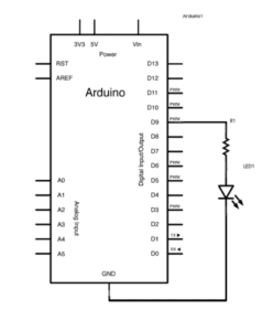
Schematic

Video

Process

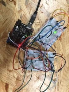
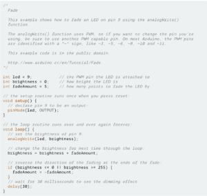
Before I started building the circuit, I asked my partner Caren if she’d like to connect it to my computer because I wanted to practice coding and she agreed. But then I found I just needed to open the code in Examples. I thought it was easy, but Caren reminded me to select the proper Boarder and Port which I forgot to do. Thanks to her. All other things just run smoothly because this circuit only consisted very few components. We connected them according to the schematic.

  • Circuit 2: toneMelody

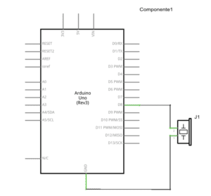
Schematic

Video

Process

This circuit was also done smoothly because it is similar to Circuit 1. But during the process we didn’t unplug the adapter and one teaching assistant came to warn us. Well, I will pay attention to it next time. 

  • Circuit 3: Speed Game

Schematic

Video

Process

To be honest, this circuit was a total mess. When we finally finished building it, there popped up a prompted box saying something used too much power. Anyhow, it didn’t work. So we turned to that teaching assistant. He unplugged the adapter and found it hot, then he checked our messy cables carefully and found one electric wire connected the power source to ground and formed a short circuit. He also helped us unplug 2 useless wires to simplify our circuit. I think the cause of our false is our terrible division of labour and messy order of connecting components, which need to be arranged reasonably next time.

Questions

1. Nowadays, technology has penetrated into our daily lives and no one can live without it. There are so many examples, household appliances, vehicles, PCs, smart phones, etc. But what we have access to in our daily lives are mostly multimedia computers and intermediate computers, which have strong output functions but low input functions. When we build the circuits in interaction lab, we can use Arduino, which belongs to another type of computer: Microcontroller. It can “capture and convey a person’s expression”apart from “trying to imitate the autonomy of human beings” so that “the gap between the physical world and the virtual world” can be bridged.

2. If I have 100000 LEDs of any brightness and color at my disposal, I would like to open an LED art gallery where innumerable “celebrated paintings” all over the world composed of LEDs were exhibited here. They can not only change from one painting to another everyday, but also turn static paintings into dynamic ones with some creative ideas. Although it’s of no practical use, but it can be a tourist attraction which becomes different everyday.

Reference

https://drive.google.com/file/d/1uviCK0V71cQpA76PV9PK03Df14vcsd0y/view

Recitation 2: Arduino Basics by Malika

Materials

Arduino Uno: the codes are processed here.

USB A to B cable: connects the Arduino Uno to the computer.

Breadboard: a station to hold the circuit.

Buzzer: gives noise when applied current. serves as the output.

LEDs: give light when applied current. serve as the output.

220-ohm resistors: add resistance to the circuit, lower the current so that buzzer or the LEDs won’t be burned.  

10K-ohm resistors: same as above, but the resistance is lower.

pushbuttons: when pushed, allow current to pass through.

arcade buttons: same as above.

A handful of jumper cables: breadboard friendly, easy to use.

Circuits

Circuit 1: Fade

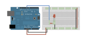
diagram found here

Circuit 2: Tone Melody

diagram found here

Circuit 3: Speed Game

diagram found here

Circuit 4: 4 Players Speed Game

Processes

My partner and I finished the first three circuits smoothly. We spent most of the time studying circuit 3 and its code, trying to build circuit 4. Our code for circuit 4 is as follow:

We cooperated with another group and connect our two breadboards together onto our Arduino Uno. 

It was a lot of fun studying the code and the circuit, trying to figure out which part does what. When it worked, we were all so thrilled and proud of ourselves.

Reflection on the questions

Question 1

To be honest, I rarely ‘use’ technology in my daily life rather than ‘benefit from’ it. Before taking the Interaction Lab, I almost never had the chance to truly ‘use’ the technology to accomplish something. As for the circuits, the only interactive one for me was the fourth one. My partner and I really studied it, tried to ‘communicate’ with it. And it ‘reacted’ to our input by giving us its output. The fourth circuit was our original work. We ‘used’ technology to create that game for four.

Question 2

If I have 100,000 LEDs of any brightness and color, I would distribute a questionnaire, asking random people if they are willing to participate in an experiment. I would give every participant an LED of their choice of color, along with a device that will make the LED light up when walking pass another LED with the same color. I want to see what kind of interesting story would happen when two strangers walk towards each other and find out their LED lights up.

IxLab(Young) – Robert – Recitation 2 – Arduino Basics

Information:

Time: 13:45-15:00, 22 February 2019

Location: 825, 8th Floor, NYUSH

Partner: Sheldon Chen

Preparation: 

Materials list from Introduction to Recitation 2

Process:

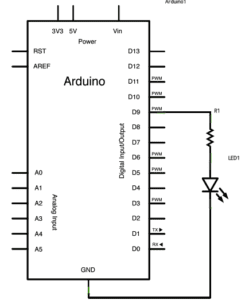
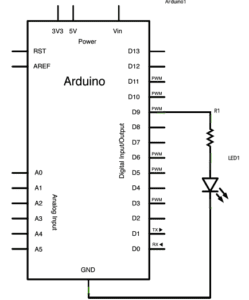
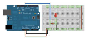
Circuit 1: Fade

Schematics from Introduction to Recitation 2

Hardware Required: 

  • Arduino
  • LED
  • 220 ohm resistor
  • hook-up wires
  • breadboard
Image from Arduino.cc
Code from Arduino.cc

As a programmer and circuit builder, when you get both the physical map and the code, everything seems easier. So we just copy and paste the code (Of course we read it carefully and got to understand it), and built the circuit following the physical map. 

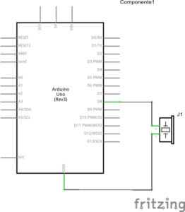
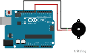
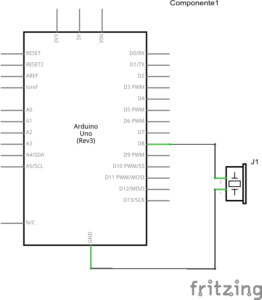
Circuit 2: toneMelody

Schematics from Introduction to Recitation 2

Hardware Required:

  • Arduino
  • Buzzer
  • Hook-up Wires
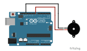
Image from Arduino.cc
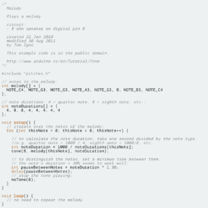
Code from Arduino.cc

Also following the physical map on the website, we quickly built the circuit. After understanding the code slightly, we ran it and heard the buzzer singing. 

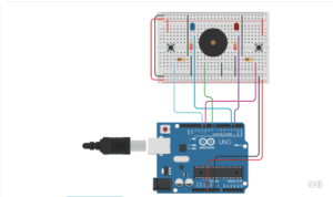
Circuit 3: Speed Game

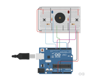
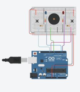
Image from Tinkercad.com
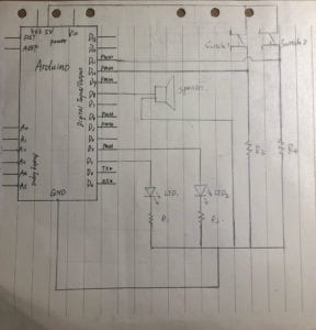
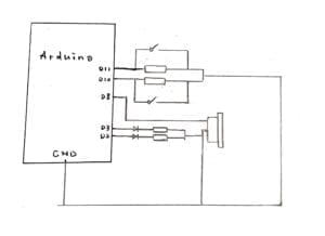
Draft of Schematics for circuit 3

The first time we saw the physical map on the website, we were like:

What???

This circuit is more complex so that for 5 mins we can not figure out how it was connected. Then we decided to use the same method: following the physical map. We built the circuit for more than 5 mins because there are too many wires and it was easy to be confused. The holes and numbers on the breadboard are so small that my eyes felt painful after this. However, we still successfully made it work. 

After we played the speed game for couples of times, we started to draw the schematics. I had no ideas in the beginning. However, instead of analyzing the physical map, I tried to draw by following wires with different colors. By doing so, I finally finished the schematics and knew how the circuit works. 

Circuit 4: Four-player Speed Game

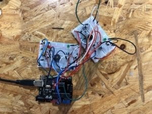
After organizing a team, we worked in cooperation with a due division of labor. For me, my job is to build the circuit for four players with my partner. In the beginning, our idea is to parallel two circuits with the same digital output but with only one power. However, Eric gave us a hint that we actually only needed one Arduino. So we built the circuit which I thought was right and ran it with the code which my partner thought was right. Sadly for us, we failed.  Press of two buttons could not be counted and the numbers on the screen were always zero. There was no more time for us to find the problem, but I think we will try to figure it out sometime. 

Picture of our circuit

Question 1:

 I think interaction is the “communications” between you and your machines. Like using your computer is interaction because once you click on the screen or press on the keyboard, your computer will process to make an output, no matter it is opening a web page or typing some words in the doc. However, as the article mentioned, now what we can do is make “computer for the rest of you”. With physical computing, we can make interactions more than only including your eyes, ears, and fingers. Like the functions on the new LG phone, though they are not the brand new one, which Samsung did the floating gesture first, it still shows the new possibility for people to have new interactions with the devices that we are familiar with. 

Question 2:

If I have 100,000 LEDs, I might use it to build a big phalanx displaying on the top of NYUSH. There will be a QR code on the entrance door of NYUSH. If you scan it, you will see the web app I designed to write down what you want to say or vote for the good sentence you like. The most voted sentence will be displayed on the phalanx and show everybody the writer’s brilliant idea. 

Recitation 2: Arduino Basics by Haoquan Wang (Kenneth)

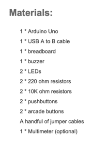
Materials:

1 * Arduino Uno
1 * USB A to B cable
1 * breadboard
1 * buzzer
2 * LEDs
2 * 220 ohm resistors
2 * 10K ohm resistors
2 * pushbuttons
2 * arcade buttons
A handful of jumper cables
1 * Multimeter (optional)

Circuit1: Simple fade

Process: We followed the instruction and diagram to connect our circuit and the process was quite smooth, which means that we didn’t encounter any problems. Our circuits successfully worked.

Circuit 2: toneMelody

Process: At first we thought that we need to connect the circuits in the same way of the first circut. So we connected the power pin to the breadboard, as what we did in the first circuit and it is not supreised that we failed. After the instruction and expound from instructor, we changed our circuit into the one matching the provided diagram and it worked.

Circuit 3: Speed Game

Process: We followed the simulating picture to connect the circuits. But when I connected the circuit, I forgot to connect a wire, which lead one of the resistors to the ground. It caused that the left button circuit failed to be connected as a closed circuit. We found out this problem by checking the inspector. It supposed to be shown a number of player1 on the screen but no matter how many times I pressed the left button, there was no any change on the screen. Thanks to the remind of Jingyi, we added that wire to breadboard. 

Question1: 

In my definition, interaction means a thing that involves a reciprocally active, dynamic process among people or between people and electronic devices. Taking the example of the text. The communication between human and computer is also a kind of interaction. That communication involves the input motion of human such as typing and speaking, and the output of computer such as screen change and program runniung. It is reciprocal, active and dynamic. Also from the example of the circuit of toneGame, we can see that the interaction part of that circuit involes not only two users but also computer program. According to the users’ instruction, the computer will provide different reaction back to users accordingly. That is what I think about the definition of interaction.

Question2:

If I have 100,000 LEDs of any brightness and color at my disposal, I want to make a huge led light board. It can receive different sound waves and translate them into digital signal. Then according to a specific formula, the led light board can show different colour. I want to build this program for deaf people, which cannot experience all kinds of sound in the world. I hope that I can find a way to help them enjoy those sounds that they cannot imagine.

Recitation 2: Arduino Basics by Celine Yu

Date Of Recitation: February 22,  2019 

Documented on: February 25, 2019

Partner: Citlaly Weed

Reflection: Recitation 2 focuses on familiarizing oneself with the Arduino software and hardware through a total of 4 attempts at different circuits. For all circuits, I worked with my partner, Citlaly, who I had a great time creating circuits with. For continuity and time-efficient reasons, we decided that we would use Citlaly’s laptop for all coding and Arduino exercises. Since the both of us had already acquired an amount of knowledge from the first recitation and listened closely during the week’s lectures, the diagrams for circuits 1, 2 and 3 were all quite straightforward. We completed all 3 required circuits, and made significant attempts at circuit number 4 but was ultimately unable to complete it due to time constraints. Citlaly and I had chosen not to replace the switches with arcade buttons from the first recitation in order to leave more time for circuit 4, which was proven to be quite difficult.

Circuit 1: Fade

The purpose of the first circuit was to have a LED fade both in and out with the Arduino software and physical board. Citlaly and I grabbed two jumper cables, a 220-ohm resistor, and a LED to accompany the Arduino board and breadboard. We followed the clear diagram provided on the recitation website and got straight to work. The first step was to place the 220 ohm resistor onto the breadboard and into row 2 of columns D and G, knowing that the breadboard’s connection is divided into left and right. We then used a green jumper cable to connect one end of the resistor to the power on the Arduino board. Afterward, it was time to plant the LED. We made sure that the anode connected with the resistor and ultimately to the power supply by placing it in row 2 of the breadboard. Lastly, Citlaly and I attached the cathode end of the LED to a red jumper cable in row 5, which we would then connect to the Arduino board’s ground. We connected the circuit to Citlaly’s laptop through the Arduino board and continued to follow the instructions provided. We opened the Arduino software, went to file and found the Fading example under 0.3 Analog. Citlaly uploaded the code, but we were met with our first failed attempt. The LED did not light up, nor fade in and out as it was supposed to perform. This is when I remembered a tip our professor, Mr. Young had informed us about in class. I went to tools and looked down to find the Board and Port categories, and selected the appropriate port for the Arduino software. After completing the selection, we tried to upload the code once again, and to our surprise, the circuit worked this time around.
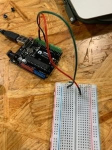
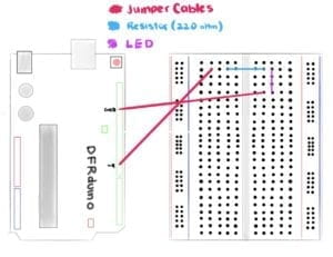
Circuit 2: toneMelody

The output that Citlaly and I strived to achieve for circuit 2 was for a speaker to emit a specific melody produced within Arduino. We made sure to disconnect the circuit from the laptop and remove both the resistor and LED from the breadboard as they were no longer needed. Citlaly and I placed a speaker or buzzer near the middle of the breadboard, ensuring that its pins were connected to separate sides of the circuit board. Following this, we connected the red and green jumper cables to each side of the buzzer and connected the Arduino board with the laptop once again. Citlaly and I were confident that we hadn’t made any mistakes and continued to open a new Arduino page with the toneMelody example found under 0.2 Digital. Unfortunately, we were unable to have the circuit working on our first attempt. Since we were confused as to what went wrong during the seemingly simple circuit, we asked for help from the teachers and assistants present during recitation. We soon learned that we had misplaced the red and green jumper cables that connected to both ground and power on the Arduino board to the incorrect sides of the buzzer. Our initial belief was that the position in which the components were connected did not matter, as long as they were attached, the circuit would work. This was ultimately, incorrect. We turned the buzzer around so that the anode side would connect to green power cable, while the anode would attach to the red ground cable. With our second attempt, we were able to successfully make the buzzer release a small melody, essentially completing the second circuit.
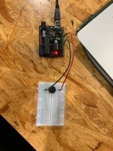
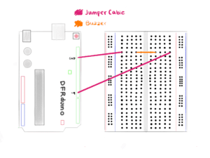
Circuit 3: Speed Game

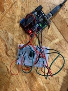
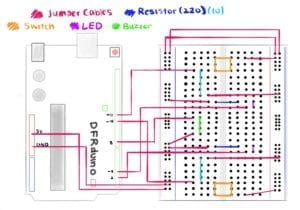
The third circuit was by far the most interesting circuit as well as the most difficult one to follow in terms of its foundation for it implemented a sense of interactivity for both Citlaly and I. We placed all major components down such as the buzzer, the switches, the LEDs, and the resistors in their positions on the breadboard and continued to interconnect all the pieces with an assortment of jumper cables that ranged from short to long and long to short. With the jumper cables, we also connected the breadboard to the Arduino base by utilizing slots, D11, D10, D8, D3, D2 as well as GND and 5V. When it reached this part of the circuit, things began to grow confusing as the number of components on the breadboard increased with each step. The circuit, unfortunately, did not prove to be a success as the LEDs failed to show any response to the manipulation of either switch. We then decided to utilize the multimeter to test the resistors, as we were aware that any single mistake would be crucial to the circuit. The multimeter discovered that one of the resistors presumed to be of 220 ohm was in fact a 10k ohm resistor. We immediately, switched the 10K ohm resistor with a new 220 ohm one and replaced it on the breadboard. We did a double take of the entire breadboard and made another attempt to get the speed game working. With the port and board categories accurately chosen, the Arduino board connected to the laptop and all components seemingly fitted into their rightful positions, we uploaded the Arduino code once again. Both of us then pressed the switches repeatedly and vigorously in an attempt to have our LED turn on first, which ultimately resulted in Citlaly’s victory. Circuit 3 was confusing at first, but after we traced our steps and focused our attention on each and every component, we were able to spot the mistake almost immediately, which allowed us to complete the third exercise with ease.
Circuit 4: Four-Player Speed Game

For this optional circuit, Citlaly and I partnered up with two other classmates from our recitation. We began to discuss the solutions that could help us transition our two-player game into that of a four-player one. We decided to list down the number of our switches, and the colour of the jumper cable that would connect to each slot in the Arduino board and breadboard. We noted the number of the slots we used as well in order to implement them into our code in the future. We soon hit a rough patch while trying to interconnect both breadboards with a single Arduino base. Unfortunately, due to time constraints, our group was unable to complete the fourth circuit despite our great efforts and attitude.

Questions and Answers:

Question 1: Reflect how you use technology in your daily life and on the circuits you just built. Use the text Physical Computing and your own observations to define interaction.

Answer 1:  Technology is found everywhere and is now inevitable when it comes to performing certain tasks on a daily basis. I use the microwave for breakfast, my laptop to complete assignments, and my smartphone to read the latest news. Technology has changed the way individuals communicate, play, work, study, learn and behave around one another. With its ever growing area for improvement and creation, technology is most of the times, created to improve all lifestyles. When this technology is partnered with physical computing, the possibilities are endless. As stated in the “Introduction to Physical Computing”, the very definition of physical computing entails the “creation of a conversation between the physical world and the virtual world of the computer”, which ultimately creates an interaction between the two worlds. According to the reading, two subjects require input, output and processing for an ‘interaction’ to occur between them,. They react with one another through a cause and effect complex that allows an output to be produced at the conclusion of the interaction. The circuits created in recitation 2 are perfect examples of physical technology combined with the wonders of physical computing. The correct wiring of components of the breadboard and the proper coding upon the Arduino software allows the circuits to produce results (output) such as: playing music, turning on/off lights as well as creating games (for leisure). The interaction between the physical world and its counterpart, the virtual world create technology designed for all audiences, and will continue to create for years to come.

Question 2: If you have 100,00 LEDs of any brightness and colour at your disposal, what would you make and where would you put it?

Answer 2: If I were given 100,00 LEDs of any brightness and any colour at my disposal, I would perhaps, If I had the knowledge and capability to do so, create an art piece that would have all 100,000 LEDs positioned so close together that from a distance they would appear to create a flat surface of lights. I would then create a program that allows the user to draw a simple image, or write a note that would eventually project onto the 100,000 LEDs as if it were being projected onto a TV or a screen. Each LED would change into a colour in respects to the design and or message the user has created on the program. Ultimately, it would enlarge the design and bring the piece to life by allowing it to shine through the lights of 100,000 LEDs. This idea would of course, require a lot of knowledge in regards to both computer programming and light engineering, but would ultimately be an amazing project if it were to be created in real life.