Lab Report: Final Project Documentation (Artificial Muscle)

3.2 EAPs Manufacturing

  1. Cut Nafion-117 into 2 x 1cm x 5cm, 2 x 2cm x 5cm, 2x 1cm x 10cm, 1 x 2cm x 10cm.
  2. Roughen the surface of Nafion-117 polymer by sandpapering.
  3. Prepare an aqueous solution of the complex ([Pt(NH3)4]Cl2 or [Pt(NH3)6]Cl4).
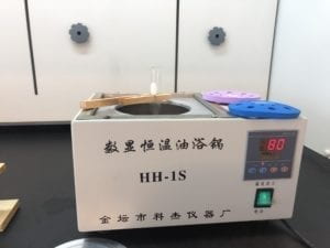
  4. Place the one cut of the polymer in the stirring Pt solution at 60◦C for 1 hour.
  5. When Pt particles have immersed into the polymer, add 5% N2H4·H2SOsolution.
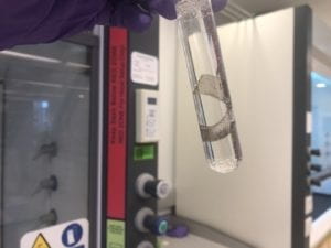
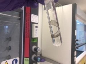
  6. When grey metallic layers form on the membrane surface, finish the experiment.
  7. Repeat the process.

3.3 Performance Testing 

Dry Test:

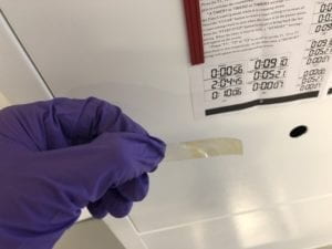
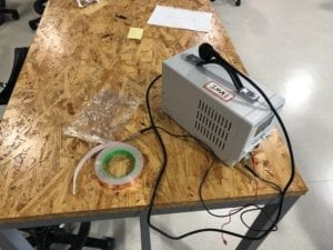
Using ATTEN TPR3003T’s Regular DC Power Supply and 2 pieces of conductive tape on both sides of the IPMCs polymer.

Modify the voltage from 0V to 30V to activate the polymer. Then modify the current from 0.1A to 10A to supply different intensity electric field level with the combination of various voltage.

Underwater Test:

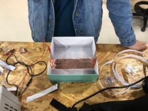
Using ATTEN TPR3003T’s Regular DC Power Supply and 2 pieces of wire with an insulating layer on the side surface touching both sides of the IPMCs polymer.

Modify the voltage from 0V to 30V to activate the polymer. Then modify the current from 0.1A to 3A to supply different intensity electric field level with the combination of various voltage.

Experiment Results Analysis

First Experiment Result: Failed

Reasons’ Analytic Report:

  1. The previous stirring time is not enough for Pt ions to attach on the surface of the polymer.
  2. The  NaBH4 solution was mixed with the Pt solution, which caused waste of the Pt ions in solution.
  3. The concentration of the ammonium hydroxide solution is too high and caused the high pH level of the solution. Finally, it results in the precipitation of Pt.

Second Experiment Result: Half Success

Reasons’ Analytic Report:

  1. The oxygen in the open air oxidized the Pt that was successfully attached to the polymer.
  2. The Pt on the polymer is still not enough after a single round of the experiment. The above procedures need to be repeated 3-5 times to ensure the efficiency of the polymer.

Third Experiment Result: Half Success

Reasons’ Analytic Report:

  1. Tried to use a higher concentration of NaBH4 solution. However, it turned out to be too much. The Pt that had already attached on the surface in previous steps drop down because of the fierce bubbles caused by the reaction.
  2. The time is so limited that the reaction is not fully completed.

Fourth Experiment Result: Success

Reasons’ Analytic Report:

  1. Cut the edge of the polymer in order to avoid the electricity to go through the edge to another surface.
  2. Substituted the NaBH4 by the N2H4·H2SO4. This change narrowed down the cost of manufacture.

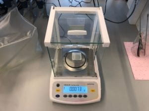
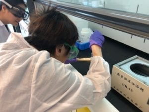
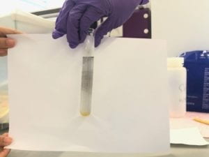
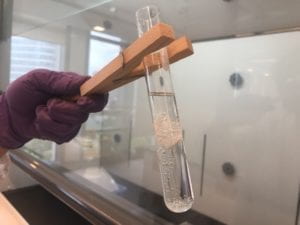
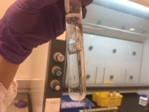
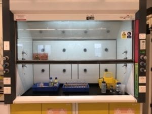
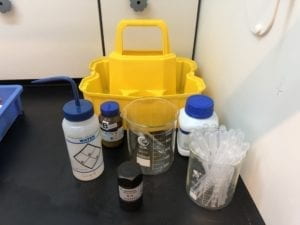
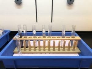
Figures and Videos for Step 3.2 & 3.3


Swarm Project: End Result

As it turns out, our final project ran into a few issues in terms of putting all the code together and running final testing with serial communication. As a result, we did not manage to get the swarm running, but we do have the main code, as well as the specific functions for flipping camera axis. 

As stated, here was our original plan:

  1. Object is detected within boundary
  2. Robot with the shortest distance to the object will move first to “attack” it
  3. The robot will navigate to the object and attempt to push it out the boundary
  4. If the robot is unable to do so (most likely if the object is too heavy), the rest of the bots will navigate to the object as well, forming a chain sequence behind the first bot to help push the object out
  5. Once the object is pushed out, the bots will resume original reset positionsOf course, we did manage to code every step we intended to run, including an extra step of solving the camera axis inversion.  Here are some problems we managed to solve during the process:

calculating the position of bot, as well as the angle it is facing (performed by recognizing the four corners of the bot’s QR code)

def calcBotData(data): #data has the four corners #calcBotData returns the x,y of the center of the bot and the angle it is facing, can also be used for the enemy bot
id = data[0]
corner1 = data[1]#corner1data Should be at the location of the head
corner2 = data[2]#corner2data Should be at the location of the tail
#these corners are across from each other

#calculating center of the bot
x = (headx + tailx)/2
y = (heady + taily)/2

headx = corner1[0]
heady = corner1[1]
dy = heady - y
dx = headx - x

angle = math.atan2(dy, dx)
if angle < 0:
angle = 2*math.pi - angle

#THIS ANGLE IS IN RADIANS
return [id,x,y,angle]

sending ‘reinforcement bots’ in the case where one bot cannot push out the object

def initiateCall(availablebots, enemy, dest):

reinforcementBot = availablebots[0] #store first bot in list into variable
availablebots = availablebots[1:]

distance = math.hypot(reinforcementBot[0][0] - enemy[0], reinforcementBot[0][1] - enemy[1])

timeA = 6.38 * orient(reinforcementBot, dest)
timeD = 60 * distance

command = str(reinforcementBot[0])+ ",0,"+ str(timeA)
#SEND TO SERIAL
sleep(timeA + 2)
command = str(reinforcementBot[0])+ ",1,"+ str(timeD)
#SEND TO SERIAL

timeA = 6.38 * orient(reinforcementBot, dest)
command = str(reinforcementBot[0])+ ",0,"+ str(timeA)
#SEND TO SERIAL

command = str(reinforcementBot[0])+ ",1,0"
#SEND TO SERIAL

return availablebots

resetting the bot position 

def reset(robots):
received = robots
for i in range(3): #for each bot
move[i][0] = bot[i][0]
for j in range(1,3): #calculate vector, j = 1 for x, j = 2 for y
move[i][j] = start[i][j] - received[i][j]

if move[i][1] != 0: #exclude x = 0
tanAngle[i] = move[i][2] / move[i][1] #calculate tan, y/x
if move[i][2] > 0: # y > 0
angle[i] = math.atan(tanAngle) #angle = 0 ~ pi
elif move[i][2] < 0:
angle[i] = math.atan(tanAngle) + math.pi #angle = pi ~ 2pi
elif move[i][2] == 0: # angle = 0 or pi
if move[i][1] > 0: #x > 0
angle[i] = 0;
else: #x < 0
angle[i] = math.pi
else: # x = 0
if move[i][2] > 0: # y > 0
angle = math.pi / 2
elif move[i][2] < 0:
angle = math.pi / 2 * 3
else:
angle = 0

However, due to time constraints, as well as the ambitious nature of our project, we had to implement the training time during the end of the week, which resulted in some setbacks. Namely, we didn’t expect to have so much trouble sending signals to the bot using serial, and after several attempted test runs, we had to leave the project as is to work on the final. 

With that being said, because the main issue was that the serial wasn’t working, we actually have no idea if the code runs properly or not. Our hope is that for future improvements, we would tackle the serial issue, and then test out the full swarm code if possible.

Lab Report: Collective Decision

Step 1: Plan

After the in-class discussion, we decided to make a collective decision project called “Gathering Up”.

Main Procedures: 

  1. During the project, keep sending the (x, y) position to the Robotbits.
  2. The 5 Robotbits will be spread on the ground.
  3. The 5 Microbits will calculate the distances between every 2 Robotbits.
  4. Every 2 Robotbits that are close to each other will gather together.
  5. The Microbits will calculate the distances between every 2 groups of Robotbits.
  6. The most closed 2 groups of Robotbits will gather up.
  7. The 5 Robotbits are all clustered.
  8. The 5 Microbits display “Robotbits Assemble!!” (and maybe an audio clip).

Materials:

Microbit x 5

Robotbit set x 4 (optional)

HD 920c Logitech camera

Mac mini

Aruco markers

|

Anaconda-Navigator

OpenCV Library

Mu-Editor

Microbit Wireless Communication Module

Step 2: Code

Code for Computer Vision:

https://github.com/todocono/arUco

Code for Robotbit communication:

https://github.com/todocono/birs2019s

Additional Resources from Github Repository:

https://github.com/krawc/arUco

Step 3: Reflect on the process

The collective decision is really a challenging topic to address.

It requires many technical skills like the application of openCV and wireless communications between Microbits.

Besides, it needs a whole group of student (for example, we have 5 people in our group) to adjust their schedule to create a perfect time for all of the members to work on the project.

However, the process of making the project is exciting and interesting. 

Most importantly, we learned a lot from this collaboration.

Final Project: Artifical Muscle Based on Electroactive Polymers

Introduction

Our idea come from two perspectives:

1. After the locomotion lab, we realized that although we tried to make robotic arms and legs, we cannot avoid the use of motors, servos and other metallic compartments. Although they seem to function well, they are different from real animal movements. In real world, no animal have this type of rotating body part. Thus, they have certain limitations and drawbacks. As the real animals’ locomotion is driven by muscles, we want to develop real artificial muscles for new foundation of robotic locomotion.

2. We at first want to make a jellyfish floating in the air. Then after research we discovered jellyfish move by propulsion using the muscle in its body.
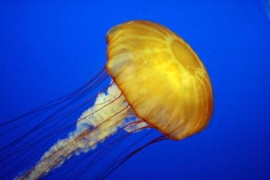
The muscle expand to create a negative pressure to inhale water, then contract to propel them out. So we shift our focus on developing an artificial muscle.

After research, we focused on a new material: Ionic Polymer-Metal Composites (IPMCs), which is a subset of Electroactive Polymers (EAPs). This kind of material can conduct movements such as shrink and stretch under a low voltage. It can function as artificial muscles for a new foundation of robotics design. Then we researched its property and mechanism, and designed experiment to manufacture it.

EAPs and IPMCs

We researched on the development and mechanism of IPMCs and EAPs:
EAPs is firstly invented by Wilhelm Rontgen. Then in the 1960s, a major breakthrough of EAPs took place, and the first electrically conducting polymers were discovered by Hideki Shirakawa. In the early 1990s, IPMCs were developed and appears to be much more effective compared to EAPs. It needs only 1 or 2 volts to motivate, and this became a significant discovery for the bio-inspired robotics’ development.

We discovered that EAP materials have two categories, Dielectric Electroactive Polymers (DEAP), whose squeezing and stretching behavior is caused by electrostatic forces on the surfaces. The force stretches and squeezes the insulated polymers in the middle. This type of material is resilient and relatively easy to manufacture. However, it requires thousands of volts to function. The other type is Ionic Electroactive Polymers (IEAP), which is represented by IPMCs. The material is made up of an cation or anion exchange polymer with its two sides plated by metals. When being added voltages, the surfaces creates an electric field in the polymer, moving the corresponding ion to one side. However, the detailed theory behind its behavior is not fully understood.

However, the artificial muscle made of IPMCs is still hard to be manufactured, and the quality of the material is still beyond control. Thus, base on previous research done by other scientists, we want to find a simple procedure for common students to produce their own artificial muscle from EAPs, and find ways to apply this new kind of artificial muscle to the bio-inspired robotics.

Manufacturing Procedure

we studied various materials including PDMS, Nafion, Platinum, Carbon. After thourough research, we discovered Nafion 117 and Platinum is a great material combination for making IPMCs.

The structure of Nafion 117

We decided to use NaBH4 to reduce Pt ion to nanometer scale Pt metal particles after we let Pt ion sink into the polymer, based on the formula:

NaBH4 + 4Pt2+ +8OH− ⇒ 4Pt + 16NH3 + NaBO2 + 6H2O.

Below are the manufacturing guide proposed by us based on research and experiment:

Material Preparation
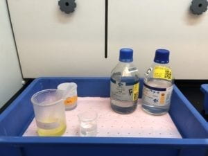
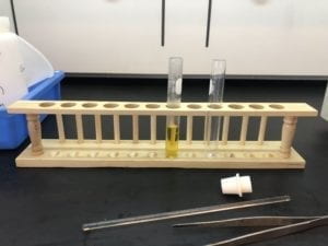
Equipment: Beaker, Glass Rod, Dropper, Test Tube, Forceps, Water Bath, pH test paper.
Reagents: 10cm x 10 cm Nafion-117 Polymer, Platinum standard solution, diluted hydrochloric acid, 1% ammonium hydroxide solution, 10% NaBH4

Manufacturing
1. Cut Nafion-117 into 2 x 1cm x 5cm, 2 x 2cm x 5cm, 2x 1cm x 10cm, 1 x 2cm x 10cm.
2. Roughen the surface of Nafion-117 polymer by sandpapering.
3. Mix Pt solution with ammonium hydroxide until pH is 3.
4. Place the one cut of the polymer in the stirring Pt solution at 80◦C for 5 minutes.
5. Move the polymer to NaBH4 solution at 50◦C, observed bubbles emerge on the polymer. Wait for the reaction to be over.
6. Repeat process 4-5
7. When dense grey metallic layers form on the membrane surface, finish the experiment.
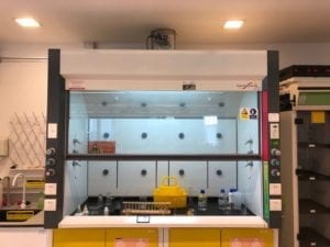

Our lab

Lab Record

First Experiment:

To test what is the best pH for Pt solution, we first made the pH = 6, yet a unexpected reaction happened and precipitate most Pt ion.
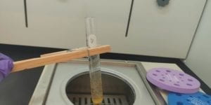
high pH caused Pt ion, chlorine ion and ammnonium ion to form ammonium chloroplatinate

Then we followed the instruction of a paper to mix Pt solution with NaBH4, which cause more trouble, as the Pt ion in the solution react directly with NaBH4.
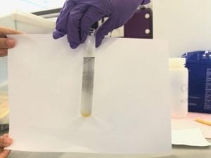

The result of mixing Pt solution with NaBH4 together.

First Experiment Result: Failed
Reasons’ Analytic Report:
The previous stirring time is not enough for Pt ions to attach on the surface of the polymer.
The NaBH4 solution was mixed with the Pt solution, which caused waste of the Pt icons in solution.
The concentration of the ammonium hydroxide solution is too high and caused the high pH level of the solution. Finally, it results in the precipitation of Pt.

From it we designed new procedure proposed in the beginning.

Second Experiment:
We follow our procedure clearly and successfully plated Platinum on the polymer. However, we didn’t repeat 4,5 process enough and the nanometer scale Pt scatter loosely on the polymer, which are quickly oxidized after we took it out.
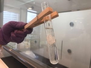

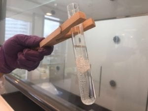
Polymer in Reaction: The bubbles are ammonium.
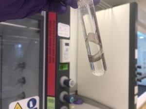

Polymer plated with nanoscale Pt

Second Experiment Result: Half Success
Reasons’ Analytic Report:
The Pt that was successfully attached to the polymer was oxidized by the oxygen in the open air.
The Pt on the polymer is still not enough after a single round of the experiment. The above procedures need to be repeated 3-5 times to ensure the efficiency of the polymer.

We knew we need to repeat procedure 4 and 5 until a dense layer is formed on the whole surface of Nafion.

Third Experiment

In the last repetition of step 5, we tried reduction agent with higher concentration to accelerate. However the reaction is too violent that the bubbles flushed all Pt particles down to the bottom of the test tube.
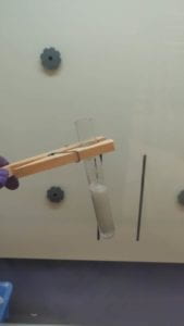

Too violent reaction

Third Experiment Result: Half Success
Reasons’ Analytic Report:
Try to use a higher concentration of NaBH4 solution, however it turned out to be too much and the Pt that had already attached on the surface in previous steps, drop down.
The time is so limited that the reaction is not fully completed.

Fourth Experiment: Succeed!

We used hydrazine sulfate as reduction agent this time and we applied it in a very diluted solution with a very long reaction time (almost 12 hours).
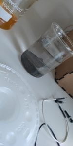
The contraction is very slight because it is a air test. The material performs better in solution base. Yet it is easier to take photos and observe it in air.

This material can act as a new foundation for robot locomotion system design. We have studied several feasible applications:

1 Heart, Lung, and Jellyfish:
Heart, lung and the propulsion locomotion of jellyfish are similar: the muscle expands, creating a negative pressure to draw in blood, air or water, then the muscle contracts to push them out. They can be implemented by our material.
Using the IPMCs based artificial muscle as the jellyfish’s muscle underwater. The Microbit and related editor like mu-editor can be used to do the physical computing part and provide periodical voltage. The basic movement like moving forward and blood cycle can be achieved by applying different intensity of electric field.

2 Arms, Legs, and Bio-Inspired Seahorse Robotic:
The Seahorse Robotic might be the best robotic to fully utilize the feature of IPMCs based artificial muscle. By using the IPMCs with less Pt density to build the top half part of the seahorse robotic and use the more Pt density one to build the bottom half. The IPMCs’ feature of having different shrinking and stretching level under different Pt density and electric field intensity. It is similar with robotic arms and legs, where the IPMCs connects with to bones, which are assembled by a joint. (From our paper)

Paper link:

https://docs.google.com/document/d/14qt9JRaHoY7bswd0Ce1aVMzVlq7tvD74nGl1PTJUozk/edit?usp=sharing

NYU account login need to open the link and track our progress.