Week 3 – 3 VR Titles Review – Ryan Yuan

The three VR titles that I have experienced  are BBC Home, The Elder Scrolls V: Skyrim VR and Super Hot.

1. BBC Home on HTC Vive Pro

This VR experience is marvelous as I am acting like an astronaut to fix a space station. The audio effect is spatial as if I am really in an astronaut suit listening to a radio, and the sense of losing gravity really makes me feel like being in space. Even though the part that I need to press the button to catch on the bars does not make me feel real, but its physics engine that restore how it feels when grabbing something to push me forward still makes it perfect. Also the shadow and light in the graphics make the perfect enviornment of space, at the end of the experience when the station has exploede and the astronaut is floating away, it really makes me feel dizzy and helpless when I have failed to reach the station and ends up to death. Everything is real and amazing.

2.The Elder Scrolls V: Skyrim VR on PS4 VR

I fail to experience it on class, but I do have tried it else where. I have played the game on PC years ago, it is a game that I can customize a lot of things and almost do whatever I want, I can be a worrier who slays dragon and also I can use magic to fight against epic monsters. Everything are restored in the VR game which is impressive, even though the graphics is not that satisfying, but the audio part is amazing, the sound of monsters and environmental sounds, and the sound of hitting something or using a magic, these all make the game amazing. I really feel that I am being a wizard in a fantasy world, living with all kinds of species. I also need to dodge and defend in the battle, these movements also make it real as if I am really fighting with something in reality, even though I cannot feel the sense of death when my character is really killed.

3. Super Hot on Oculus

This is also a game that I have played on PC, the game is designed to kill all the enemies in slow-motion using everything you can grab within range. The way I control the character to move is not by my body movement but by the controller which make it less real, but the audio effect and the feeling of hitting something is brilliant. Even though the game is a bit violent, the experience is quite exciting. Also it is an amazing experience to move the body in a slow-motion.

Week3 – Make-up recitation – Sensors

For this make-up recitation, unfortunately my partner has sicked and did not come to here, I finished everything on my own. So this recitation is for understanding basic sensors and trying to connect them with electronic components to see how it works. 

I first chose the infrared distance sensor to make the circuit, but there is one point which is very important, there is a valid range on the packing bag of the sensor showing the rang it can measure precisely. For the sensor I use, the valid range range from 4cm to 30cm. So I come up with the idea that, I can use the sensor to detect how far my finger is from it, and by inputing the analog signal can control the brightness of a LED.

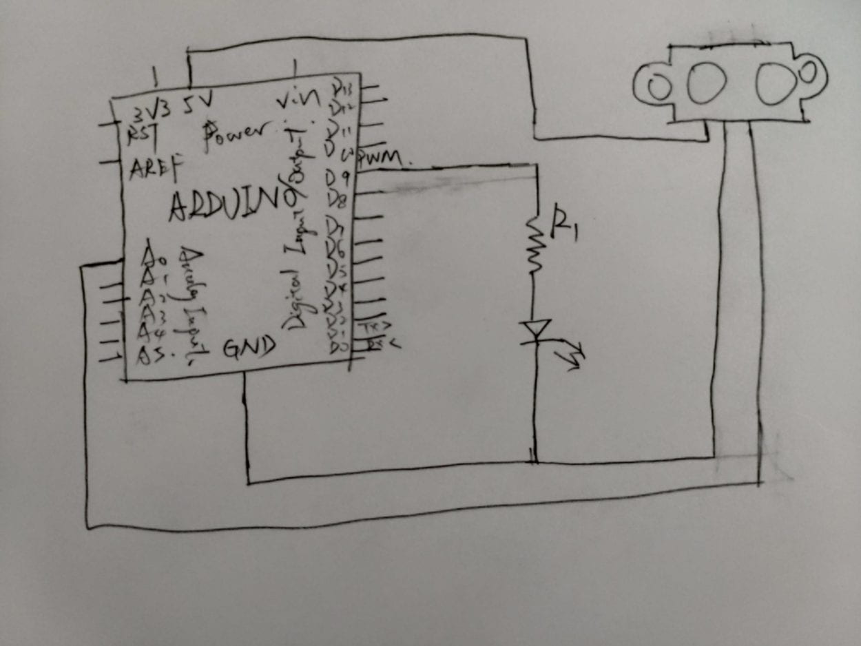
The following is my diagram for the circuit.

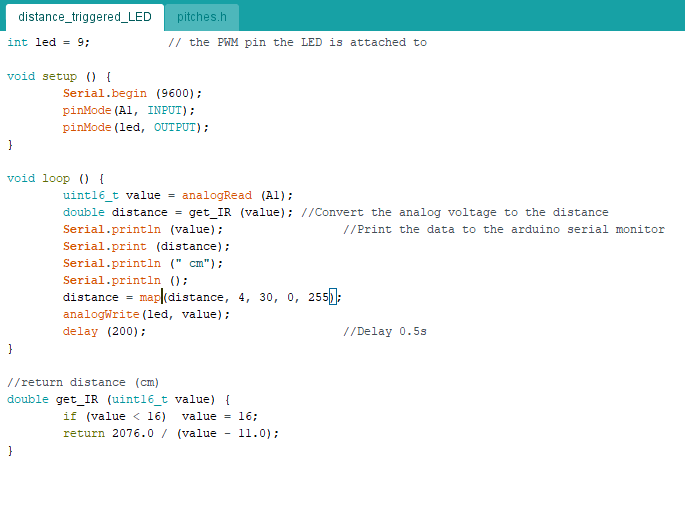
This is the arduino program

So I’m using pin A0 as the analog input, and pin D9 as the digital output, the resistor is for preventing the LED from overheating. I copy the code from the tutorial of how to get distance from the analog input, and I use map() to convert the valid distance into 0 to 255 to control the brightness of LED. I also set the delay to 200 as if the delay is too small, since the sensor is not that sensitive enough, the brightness of the LED will be very unstable.

The following is the result of the circuit.

As I finished the first circuit too fast, I got a joystick sensor to do a new one. I want to use a joystick to control four LEDs. I set the LED into a rhombus, when I pull the joystick upward, the LED on the top will be lighted up, when I pull to the left, the left one will shine, just like this. And when I press the joystick down, will all the LED shine. 

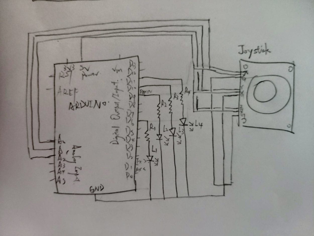
This the diagram I draw for the circuit, using three analog input to get the status of the joystick. The input is a three-dimensional coordinate, while x represents the horizontal position of the joystick, y represents the vertical one, and z represents how downward you press the joystick. The original coordinate is (512, 512, 512) and the coordinate ranges from 0 to 1024. I also connect four LEDs in parallel, each with a resisotr connected to it.

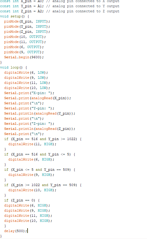
There are some error when the joystick is at the original state, so the value is not 512 but what is shown in the serial monitor, and when the joystick is pushed to the end, it might also be not that accurate so I set a range for it to make it easier to trigger the LED.

This is the code I write, and the result is in the following video which has failed. But I did not have time to check why it was wrong, was it because of the program or the circuit.

I think I will give it another try next time to find out where the problem is.

Week3 – Documentation for recitation two – Arduino Basics By Zhuochen Yuan

For this recitation on Sep 20th, what we are doing is about learning to build basic circuits for Arduino after we first get our own Arduino Kit. I’m working with James Bai, my partner.

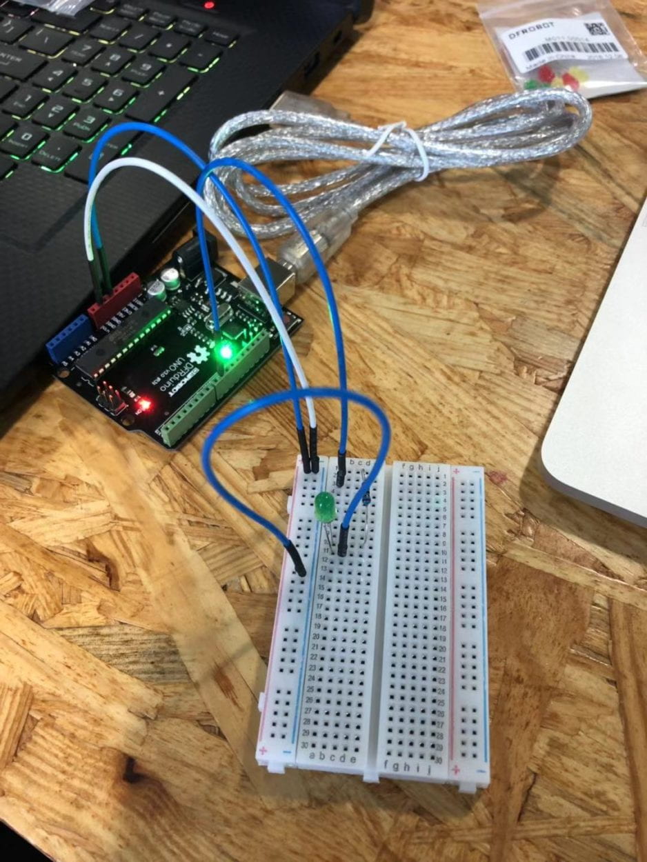
For the first circuit, the diagram is showed as following

I’ve learned that for all the circuits, I first connect the power and the ground line to the columns on the breadboard with a negative and positive symbol on it, the power to positive, the ground line to negative. For this circuit which is very simple, I only need to connect the LED with a resistor to make its light fade.  And here is the outcome

For the second kit’s diagram

Almost the same as the previous one, I just need to change the pin on the board and change the components to a buzzer, every time I press the reset button on the board will the buzzer make a certain melody which is showed in the following video

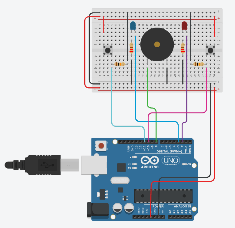
For the third one which looks muchh more complicated than the previous two

This board is for a speed game with two buttons on it, when opening the serial monitor in Arduino and restart the board, will restart the game, and the person who press the button to ten times first wins. But there might be problems that the button is not well connected or the LED is not plugged in right. For the first time James and I try the circuit, it turns out that both the LED do not light up no matter who wins, and we change the direction of the green one and the red one, it turns out that when the game starts the green LED is lighting while if player one wins the LED will be turned off which is totally opposite of what we want. So we try to redo the whole thing, and this time the green LED works while nothing happens to the red one, and we change another LED to replace the red one and it works, it is obvious that the red LED is broken for the very first time I use it.

The first trial:

The second trial

For the fourth one, since we have wasted too much time finding out that it is the LED that is broken, and the person beside us is not being cooperative I guess? So we fail to finish the optional one, a little bit pitiful. 🙁

Replies to the 16 lessons & VR experience by Ryan Yuan

Most agree:  No.6 Remote work via VR will become the norm

From my perspective, VR is going to be popular in the close future as the VR technology is developing rapidly, and it is very possible to make a simulate working environment using VR technology. By doing this will save a lot of cost not only for the company, but also for the employees. Working just need a VR headset and a handler with a place to use, both at home or in the office.  So either will save a huge space for the company to build to work and the employees can save the time and money spend on transportation and other unnecessary events, or the office building can be much smaller than now as everyone just need to use the VR equipment to work, company might only need to be focus on spaces for entertainment and relax for the employees. Also the problem of huge traffic jam during the rush hours will absolutly be remitted.

Most disagree: No.2 VR may play a bigger role in our future lives than AR

From my perspective, also being subjective, I support AR to be playing a bigger role in our future lives than VR. Even though VR is much more mature than AR now, but I believe the application of AR will be much broader than VR as it can be carried with someone and react with the surrounding environment realtime. Remote working is also possible using AR as you might just need a table or something like a board can AR set it as a office table and develop virtural working environment based on it. So comparing the mobility, AR is far better than VR, when you walk out, everything in your eyes through a AR headset will automatcially pop up an information window beside it showing any information or news related to it, for example, showing the realtime stock of an enterprise when you walk pass its building or advertisement. Also talking about intelligent home, using a AR might have a window on the interface showing the realtime data of your house, and you can remotly control it at your will.

VR experience

I only successfully experienced the BBC Spacewalk using HTC Vive Pro, the user experience is perfect, with a headphone giving me a surrounded feeling makes the VR scene more like reality to me. I’m experiencing as an astronaut in the application, my mission is to fix the space station, and by using controller can I feel like using the real hand of the astronaut to climb on the space station. And when I am floating in the space due to the explotion of the space station, the scene that the astronaut is floating everywhere really gives me a sense of dizziness. Everything is too real. I also want to try the PSVR but due to technological reason, I did not make it.

Review of the Kevin Kelly AR article

What the author has mentioned about the mirrorworld is to create another digitized ourselves in the AR world, also if everything can be digitized and be labeled in the AR world, the information we can gain by watching through a AR device will be far more than now. This is an achievable future but still need time.

Week 1 – Workshop work from Zhuochen Yuan (Ryan)

For the first recitation of interaction lab in this semester, what I have done is divided into two parts, first to use electronic components to build small ciurcuits based on the diagrams given online, then to learn how to solder wires to electronic components and to solder wires onto a switch and switch it with the switch that is already appied on the circuits to test whether it works or not. And during the whole recitation, I’m in pair with James Bai as a group.

Befor building the circuits and lookign into the diagrams, I first need to know the components I need and learn how they are represented in the diagrams as patterns.

The components are listed:

  • 1 * Breadboard
  • 1 * LM7805 Voltage Regulator
  • 1 * Buzzer
  • 1 * Push-Button Switch
  • 1 * Arcade Button
  • 1 * 220 ohm Resistor
  • 1 * 10K ohm Resistor
  • 1 * 10K ohm Variable Resistor (Potentiometer)
  • 1 * LED
  • 1 * 100 nF (0.1uF) Capacitor
  • 1 * 12 volt power supply
  • 1 * Barrel Jack
  • 1 * Multimeter
  • Several Jumper Cables (Hook-up Wires)

For resistor 

symbol:Resistor symbol                     

image:Image from Techversat.com

I don’t notice whether there are any differences between how the resistor looks like if their ohm is different, because there are several strings drawed on it.

For LED

symbol and image: Image from Tweaking4All.com

For Capacitor

symbol:Capacitor symbol

image:Image from Sparkfun.com

For Voltage Regulator

symbol:7805 voltage regulator symbol

image:Image from Electrosome.com

For Variable Resistor

symbol:Potentiometer / variable resistor symbol

image:Image from Hellasdigital.comPotentiometer pinout

For the variable resistor, I didn’t figure out why it should be connected as the picture showed above, even though it did work, it is still confusing what is the use for the left pin.

For Switch:

symbol:Push button / switch symbol

image:Image from Razzpisample

For the button, there was an interesting problem with it that I have met, that is how the current flows in it, A and D is in the same route while B and C is the same, so if I want to make it work, I should connect to one of the pins between A and D, then the other from B and C.

For Speaker

symbol:Speaker / buzzer symbol

image:Image from Sparkfun.com

There is a detail for the speaker that is there is a positive mark on it, so the pin beneath it is where the current flow gets in.

For power

symbol:12 volt power symbol

For ground

symbol:

There is always the common sense that is the current gets in from the positive side and gets out from the negative one.

For the first part, there are three diagrams given as follow.

doorbell

This one used to build a door bell.

So comes the first trial.

For the first trial comes the biggest problem I think that we have encountered during the whole recitation, I don’t know how to connect the breadboard to the ground, so before how everything look like what is showed in the video, I did not connect the power wire to the side columns that has the positive and the negative marks, even though the way I think how to make a ground line is right when connecting the power onto the middle parts of the breadboard, it is hard to arrange everything to be connected to the ground by using this way. So I asked for help from professor and she told us to connect the power two the two columns on the sides so it is easier to arrange all the wires that are connected to the power and ground directly. Then everything is much easier to finish according to the diagram.

However, as what is showed in the video above, it is obvious there must be something wrong after we finish the circuit for the first trial that the speaker is not working. After several times checking with the diagram, we cannot figure out the problem, so we asked the learning assistant to help us and told us that the way we connect the switch is wrong as what I have mentioned above talking about the switch. So here comes the second trial, which is a success.

Next comes the second diagram to make a lamp.

lamp

Comparing to the previous one, there are not many differences between them, so what we can do is just to adjust the parts that has chanded according to the diagram, changing the speaker into a resistor and a LED. (Here I think I have made a mistake, I did check which resistor I have connected to the circuit as there were two resistors one had a bigger ohm and the other smaller.) So the second one is much easier, only take a few seconds and succeeded at the first trial.

The third one is to make a dimmable lamp, the diagram is as follow.

dimmable light

For this one, the only difference between it and the previous one is there is one more variable resistor between the 220ohm resister and the LED, so what we need is only to add one more variable resistor between them. And according to the picture that I have posted above about how to connect to the variable resistor, it is also easy to finish within only one trial. And the result is that by switching the resistor can we control how bright the lamp is.

And I had thought of what if I change the resistor to the 10ohm one, as it has the same ohm with the maximum ohm of the vairable resistor, unlike the 220ohm one, the ampere could change in a bigger range which gives more choices of how bright the lamp can be. But considering about if the lamp cannot withstand such ampere, I did not give it a try.

It only took few minutes to finish the three circuits, and then came the solder section, teaching us how to solder the wire to the electronic components. Since I have tried this in my high school, so I left all works to my partner James and taught him how to use it. It is very important to keep stable during the process and we should not turn off the soldering gun until we finish all the work because it takes time to warm it up. During the whole process, James was quite struggling with it, and sometimes there were metal melt on the tip of the gun, so he needed to put the tip still on the component until the gun melt the metal again onto the component. 

After we finished soldering the wires to a arcade button, we started to do the first circuit again and use the new button.

This time, we failed again. But we cannot figure it out, and due to the limitation of time, we didn’t ask anyone to check it out. But I think it might be the problem of the switch, as I check several times at the video, I think the whole circuit is the same as how the diagram is drawn, so what might be wrong can only be the button.

For the question part

Question 1:

As what is defined in the article about interactivity, the thing that is interactive should give reaction when I react with it. So for the circuits I built during the recitation, when I press the button, the components will interact with me in the form of ringing or blinking in the ways that I want them to be.

Question 2:

 Golan Levin, an artist, in one of his TED talks, he mentioned a eye tracker sensing people’s eye movement and track it and giving back the analog signals to a huge pipe with an eye at the end of it which can follow people’s eyes and stares at them. I think this is exactly an interesting way how interactive design and physical computing are mixed together.

For all above is everything about this recitation, for further thinking, I will keep uploading my thoughts.