Introduction:
In the recitation of the first week, we learned how to build circuits to make different components working using the breadboard. We also learned how to solder so that separate components can connect to each other into one part. The details are as followed.
Materials:
- 1 * Breadboard
- 1 * LM7805 Voltage Regulator
- 1 * Buzzer
- 1 * Push-Button Switch
- 1 * Arcade Button
- 1 * 220 ohm Resistor
- 1 * 10K ohm Resistor
- 1 * 10K ohm Variable Resistor (Potentiometer)
- 1 * LED
- 1 * 100 nF (0.1uF) Capacitor
- 1 * 12 volt power supply
- 1 * Barrel Jack
- 1 * Multimeter
- Several Jumper Cables (Hook-up Wires)
Circuit 1: Doorbell


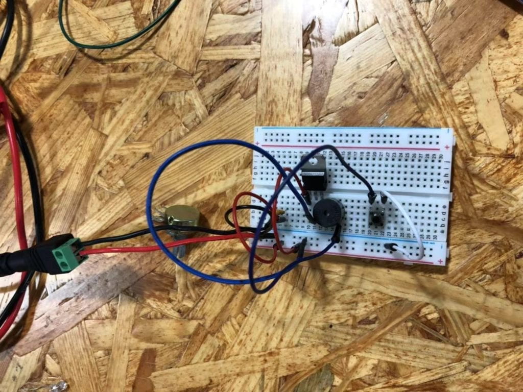
This is the doorbell circuit that my partner and I built based on the given circuit. As shown in the picture, we used a capacitor, a voltage regulator, a push-button, a speaker and several wires to build the circuit. We used the capacitor to stabilize and smooth the flow of electricity. The voltage regulator is used to maintain a constant voltage level. We used the push-button as the switch to make the circuit work when pressing it and cut when releasing it. The speaker is the output of the circuit and it would make a sound when the circuit is connected with the power. Wires help to connect different components of the circuit. At first, we built a full circuit and connected it to the power. However, something happened when we pressed the button. After we asked the instructor for help, we realized that the circuit is too compact that there was too much electricity going through the circuit. Then we made some changes to the circuit, and it worked finally. The following video can show you how the speaker circuit worked.
Circuit 2: Lamp


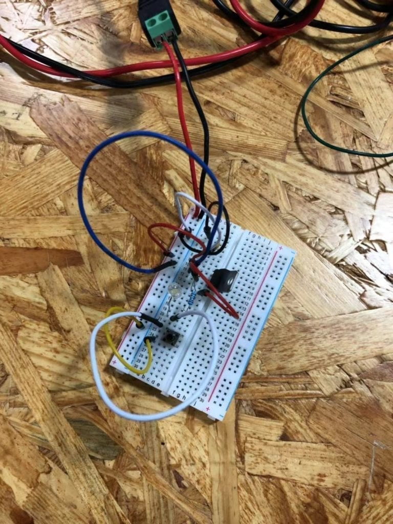
Compared to the previous circuit, the output of this circuit changed from a speaker to a lamp. We used a capacitor, a voltage regulator, a 220 ohm resistor, a lamp, a push-button switch and several wires to build the circuit. The capacitor, the voltage regulator, wires and the push-button switch play the same role as the previous circuit. The resistor is used to control the flow of current. The lamp is the output of the circuit and there would be light when the circuit is connected with the power. After dealing with the first circuit, we felt easier to make this one. Finally, by following the given circuit diagram, we built the circuit successfully. The following video is to show you how the circuit works.
Soldering
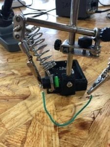
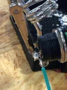
Our task for soldering is to solder two wires onto a button. We cut the wire, peeled out its skin, and then we used the soldering apparatus to solder the wires onto the button so that those wires would not fall off easily and be able to connect the button to the breadboard steadily as well. It was a really cool experience to solder things together. The following picture and video can show you how we do this.


Reading Response
Question 1:
I think the circuit that I built can be a low level of interactivity. Since both the speaker and the lamp is not alive, and they can only work when connecting to the power, they just responded to my actions/input such as pressing the push-button switch to the current flew into the circuit. As you can see, the whole process of input, process and output has been completed. So I think the circuit includes interactivity.
Question 2:
Interaction Design and Physical Computing can design games that involve with people’s interactions, make different forms of art, and build tools to help people create Interactive Art. In Zack Lieberman’s video, plenty examples are given such as moving objects that they draw, driving cars to write, and making special classes to help paralyzed people draw. As Zack said, using Interaction Design and Physical Computing to help people create art is so meaningful, just like “helping people take a breath”.