Recitation 3: Sensors by Ian (You Xu)

For recitation 3, we tried to use the Joystick module to create interactions. We used LED, buzzer, and Servo motor to make the interaction happen. Our process can be regarded as four major steps.

Step 1: Build the circuit and link Joystick module.

After reading the online document and compare it with the actual module we get, we quickly understood how it works.

After building the power and ground, we link “x” and “y” to analog pins and “z” to digital pin since “z” axis is a button. We test the input data of the Joystick by printing out the analog data to the serial monitor. When the Joystick is in the initial position, “x” is 502, ranging from 0 to 1023; “y” is 520, ranging from 0 to 1023; “z” equal to 0 when pressing the button.
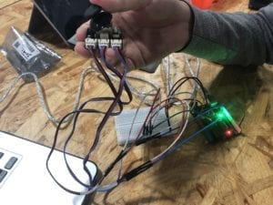
Setup Joystick

Step 2: light-up LED when pressing the button.

At first, we want to make the buzzer beeping when pressing the button. When we finished the circuit by linking the buzzer to the digital output and uploaded the code to the Arduino board, it did not work. We opened the serial monitor and thought everything went well. Then we suddenly realized that it is not merely setting the digital output could make the buzzer sound. Instead, to test our circuit works or not, we replace the buzzer to a LED. Finally, the LED blinks while pressing the button.
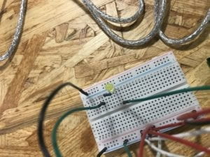
Step.2 LED

Step 3: Make the buzzer work

We continued to think about what we can do for x and y-axis. Maybe try making the buzzer work, which we failed at the first attempt, is a good idea. Therefore, we add it to the Arduino. Then, we realized that we have sample code from Recitation 2 that we can reference. We apply the sample code, setting that when we move the Joystick to where x-axis data is larger than 1000, the buzzer is supposed to ring the preset melody. We spent some time working the coding part. But it is not so difficult so that we worked it out quickly.

However, there are some parts that we can improve due to the time limit. We can change the tune of the melody. Also, it cannot light up the LED and sound the buzzer at the same time.

Step 4: Rotate the Servo motor

Till this moment, we still did not have the chance to utilize the y-axis. We think it is a great idea to associate the user’s operation on the movement of the y-axis to the rotating angle of the Servo motor. Therefore, we tried a similar circuit build as step 3. Then we used the “map” function to map the analog input ranging from 0 to 1023 to the angle of Servo motor ranging from 0 to 180. It works, and it is super fun to play with it!
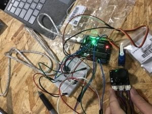
Complete circuit

Our overall circuit diagram is like this. The hand drawing part is the Servo motor.
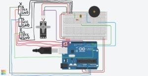
Circuit diagram

Question 1:

Combining these three parts we built together, we believe it is a functional prototype of a kind of assistant technology. With this, it can help disables to their daily lives more accessible, especially when going out. For instance, this circuit can be used as a control center on the wheelchair. When pressing the button, the torch is on, which makes disables’ mobility safer. When moving the Joystick along the x-axis, the buzzer beeping, making other passengers aware of him/her. Or use it to ask for help. Also, it can direct the wheelchair to a different direction just as easy as playing the game.

Question 2:

When we are trying to code, we referred to many tutorial and examples that are built-in or provided before. For instance, we used the sample code from Arcuino.cc to make the buzzer works. We use the basic serial and analog/digital read/out module everywhere. Based on these, we combine the modules we want to use together and add extra functions like the if-else statement. That’s how we follow the tutorials to make our project work.

Question 3:

As Lev Manovich explains in “The Language of New Media” that “the identity of media has changed even more dramatically than that of the computer” in terms of five representative areas, the development of computer also changes human behaviors a lot. The most significant influence, I believe, is the changing way for humans to interact with nonhuman objects. With the development of artificial intelligence and the Internet of Things, everything becomes interconnect and more reachable and accessible to human beings. Before the age of computer technology, we only use the object as tools that do not respond and send out information. Now, we give “life” to many things with the Internet and hardware by applying computer science. We interact with more items and objects that used to be “dead.” Now, they can “process” our “input” and give response as “output.” We are generally beginning to treat them as humans, and we are closer to all the human and nonhuman factors in the world we are living.
Recitation 2: Arduino Basics by Ian (You Xu)

In this week’s recitation, we created three circuits and used the reference code to run the circuit.

Circuit 1:

Following the instruction, we quickly built the circuit by linking a LED and a resistor to the Arduino.

We copied the code and made the LED blink successfully. Since I have experience coding Python, it’s easy for me to understand how the “for” and “if” causes work in the code.

Circuit 2:

The instruction for building the circuit is also very straight forward. We did not meet any difficulties while building the circuit.

Circuit 2

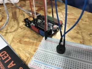
When trying to run the code, it says that the system cannot find the file “pitches.h.” Then we realized that we may need to create this file by ourselves as it is explained in the Arduino website. Since I have coding experience, I can roughly tell what the code means. However, since I know nothing about music and tone, I do not know how the melody works. I guess it’s not a big deal. In the end, the program runs successfully.

We also think it may be a good idea if we copy the code to the “void loop” function to make the melody playing repeatedly.

Circuit 3:

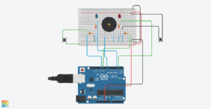
The circuit building is a little complex. We spent some time to finish it. Following the instruction, we also finished it quickly. And we change the original button with Arcade button. Following is the actual schematic.

Circuit 3 Schematic

We directly run the code and played the game multiple times.

Circuit 3

Circuit 4:

We are about to challenge circuit 4 with another group. However, we realized that while building the circuit is easy, the coding part may take some time to finish. Since we only have a few minutes left, we did not finish doing circuit 4.

Question 1:

Nowadays, we have already in an environment that is surrounded by computers. We use our phones every day. We take elevators. We wait for traffic lights. All these things matter with computer. The computing abilities of computer make our life easier by interacting with us even we do not notice.

According to Igoe and O’sulliven’s Introduction to Physical Computing, our interaction with computers consists of three parts – “input, output, and processing” (XX). Using circuit 3 as an example. We input our operation by pressing the bottom. The computer tells the result of the game as a response, in the end, regarded as output. As Igoe and O’sulliven say, “input and output are the physical parts of physical computing” that intuitively we can see. The magical part behind it is the process for the computer to do processing for the input and generate the output. This part requires algorithm and programming, which is an essential part of the computer to think like a human.

Works Cited

Igoe and O’sullivan, “Introduction,” Introduction to Physical Computing.

Question 2:

Compare to 220Ω, Higher R enables a lower current to pass the circuit. This can make the circuit works safer.

Question 3:

I would like to make it a digital mirror around a dark room. The color and brightness can show the mood and mentality of the person standing in front of it. Brighter color and higher brightness indicate a more positive state.

Recitation 1: Electronics & Soldering by Ian (You Xu)

For this week’s classes and recitation, I learned and practiced how to use a breadboard to build a working circuit. My partner and I complete three model circuits during the recitation. We encountered some problems. But we figured them out and successfully made the circuits work in the end. The documentation of how we build the circuits are as follows. We built Circuit 2 first, then Circuit 1, and Circuit 3 the last.

Circuit 2:

Introduction

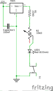
This circuit is built to work as a lamp. When pressing the bottom, it is supposed to light

Components

    • 1 * Breadboard: to connect the components together.
    • 1 * LM7805 Voltage Regulator: to make power works and current stable.
    • 1 * 100 nF (0.1uF) Capacitor: to make the current stable
    • 1 * Push-Button Switch: turn the lamp on and off
    • 1 * 12-volt power supply: make sure the power works
    • 1 * Barrel Jack: make power works
    • Several Jumper Cables (Hook-up Wires): link components on the breadboard together.
    • 1 * LED: used as a lamp that can light
    • 1 * 220-ohm Resistor: resist the current to ensure safety
    • 1 * Multimeter: to test the circuit and find the mistake

Design and outcomes

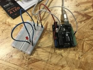
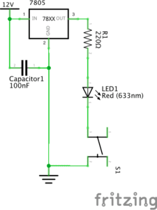
    • Following the instructions, we link these components like this.

Circuit 2 Diagram

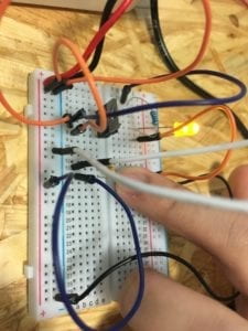
    • And it works

Circuit 2 Working

Building process

Since I have experience working on circuits and am familiar with how the breadboard works, our group does not have a problem building the circuit. However, we met with a few problems that make the circuit does not work in the beginning.

Problem 1: For the Voltage Regulator, we do not know which one is “in” and which one is “out.”

Solution: We tried to link them to power and see which one works.

Problem 2: The light is not on when the circuit is closed.

Solution: We used a multimeter to test the voltage between different parts of the circuit. Finally, we found out that we did not link the GND back to the negative electrode of the power.

Problem 3: The switch does not work. The LED is always on.

Solution: By using a multimeter to test the different sides of the switch, we found out that every two sides of this kind of switch are linked together. After understanding this mechanism, we turned the switch 90 degrees. It finally works.

Circuit 1:

Introduction

This circuit is built to work as a doorbell. When pressing the bottom, it is supposed to ring.

Components

    • 1 * Breadboard: to connect the components together.
    • 1 * LM7805 Voltage Regulator: to make power works and current stable.
    • 1 * Buzzer: to make sound
    • 1 * 100 nF (0.1uF) Capacitor: to make the current stable
    • 1 * Push-Button Switch: turn the doorbell on and off
    • 1 * 12-volt power supply: make sure the power works
    • 1 * Barrel Jack: make power works
    • Several Jumper Cables (Hook-up Wires): link components on the breadboard together.

Design and outcomes

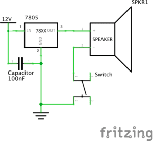
    • Following the instructions, we link these components like this.

Circuit 1 Diagram

    • And it works

Building process

On the basis of Circuit 2, we took out the LED and the resistor and replace them with buzzer. It works.

Circuit 3:

Introduction

This circuit is built to work as a Dimmable Lamp. We can turn the LED to different degrees of lightness.

Components:

besides what we have in Circuit 2, there are:

    • 1 * 10K ohm Variable Resistor (Potentiometer): to adjust the lightness of LED by turning the resistor to different ohm.
    • 1 * Arcade Button: another kind of switch.

Design and outcomes

    • Following the instructions, we link these components like this.

Circuit 3 Diagram

    • And it works

Building process

On the basis of Circuit 2, we add a variable resistor into the circuit. Again, we do not know to link it into the circuit. We tried different ways and figured out the correct one. Afterward, we change the switch to the Arcade button. It works.

Reading question 1:

       According to “What Exactly is Interactivity?” the author thinks that interactivity requires “input, process, and output” (5) and “it responds to … reactions” (6). All three circuits meet these requirements. Let’s use “doorbell” as an example. One person presses the button, giving the information that “I’m waiting outside the door,” is “input.” Then the circuit close, meaning that it gets the information and do “process” on it. As a result, the bell rings as an “output.” Furthermore, as what the author means on “interactivity,” these circuits also function to entertain the users. At least, I think it’s quite interesting to press the button and make the doorbell rings with certain beats no matter whether this “interactivity” is “subjective” or not.

Reading question 2:

       According to the three projects that Zack Lieberman introduces, we can see that these projects perfectly applies his interaction design to Interactive Art by using physical computing. So, I would argue that “physical computing” is one essential approach to make an interactive idea come into interactive experiences that work in the real world. “EyeWriter” is one example. The software and hardware, regarding as “physical computing,” makes it possible for disabled to create work in a creative way. These technologies are the key to making the design of this project works. Without “physical computing,” it could only be an ideal model instead of existing art that can interact with people.

Works Cited

Crawford, “The Art of Interactive Design,” pp. 1-5.

Lieberman, Zach, “Zach Lieberman: Interactive Art,” PopTech, 2010.