Recitation 8: Serial Communication by Gloria Yixuan Liu

Exercise One:

For the first exercise of the drawing machine, I opened the file of sending data from Arduino to Processing for multiple values first. Then I changed the port index into [0]. One important step for this exercise is to use the map function when drawing the ellipse, which I forgot to do at first. The highest value to be transformed into should be the width and height of this exercise.

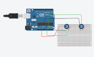
Then I built a circuit including two potentiometers, going to the power, the ground, and pin A0 and A1. After uploading the code, the data on the serial monitor was changing as I twisted the potentiometers.

It turned out that I can at least draw something by twisting the potentiometers, but the track of the ellipses was not highly controllable.

Video:

Schematic:
Code:

Arduino:

// IMA NYU Shanghai

// Interaction Lab

// For sending multiple values from Arduino to Processing

void setup() {

  Serial.begin(9600);

}

void loop() {

  int sensor1 = analogRead(A0);

  int sensor2 = analogRead(A1);

  // keep this format

  Serial.print(sensor1);

  Serial.print(“,”);  // put comma between sensor values

  Serial.print(sensor2);

  Serial.println();//////

 // add linefeed after sending the last sensor value

  // too fast communication might cause some latency in Processing

  // this delay resolves the issue.

  delay(100);

}

Processing:
// IMA NYU Shanghai

// Interaction Lab

// For receiving multiple values from Arduino to Processing

import processing.serial.*;

String myString = null;

Serial myPort;

int NUM_OF_VALUES = 2;   /** YOU MUST CHANGE THIS ACCORDING TO YOUR PROJECT **/

int[] sensorValues;      /** this array stores values from Arduino **/

void setup() {

  size(500, 500);

  background(0);

  setupSerial();

}

void draw() {

  updateSerial();

  printArray(sensorValues);

  noStroke();

  fill(#14FAEC);

 ellipse(map(sensorValues[0],0,1023,0,width),map(sensorValues[1],0,1023,0,height),30,30);

}                        //////////!!!!

  // use the values like this!

  // sensorValues[0]

  // add your code

  //

void setupSerial() {

  printArray(Serial.list());

  myPort = new Serial(this, Serial.list()[0], 9600);

  // WARNING!

  // You will definitely get an error here.

  // Change the PORT_INDEX to 0 and try running it again.

  // And then, check the list of the ports,

  // find the port “/dev/cu.usbmodem—-” or “/dev/tty.usbmodem—-”

  // and replace PORT_INDEX above with the index number of the port.

  myPort.clear();

  // Throw out the first reading,

  // in case we started reading in the middle of a string from the sender.

  myString = myPort.readStringUntil( 10 );  // 10 = ‘\n’  Linefeed in ASCII

  myString = null;

  sensorValues = new int[NUM_OF_VALUES];

}

void updateSerial() {

  while (myPort.available() > 0) {

    myString = myPort.readStringUntil( 10 ); // 10 = ‘\n’  Linefeed in ASCII

    if (myString != null) {

      String[] serialInArray = split(trim(myString), “,”);

      if (serialInArray.length == NUM_OF_VALUES) {

        for (int i=0; i<serialInArray.length; i++) {

          sensorValues[i] = int(serialInArray[i]);

        }

      }

    }

  }

}


Exercise Two:

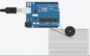
First of all, I built a circuit with a buzzer connecting to pin 7 and the ground. Then, I changed the port index to 0.

After these basic settings, I started to set the musical notes. As I wanted to play the tone of Family Mart by clicking different keys, I needed to set 5 standard notes for this melody. I used the frequency number provided by https://pages.mtu.edu/~suits/notefreqs.html . I set 5 basic notes, E5, C5, G4, D5, G5 in Arduino first, using the tone function.

For the Processing, I used the keyCode function to correspond the direction keys with different musical notes.

However, when I ran the code, nothing changed when I pressed different keys. The reason is that I simply used the “if” function for each note in both the Arduino and the Processing. I revised my code by using “if” and “else if”, and added a ‘Y’ note, which made no sound when no key was pressed.

By clicking the notes following the order of “E C g C D G G D E D g C”, you can play the tone of Family Mart.

Here’s the code and the video.

Video:

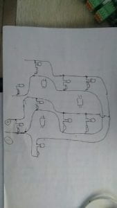
Schematic:
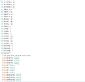
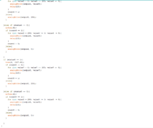
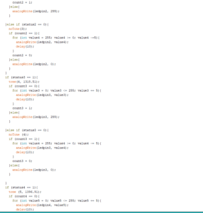
Code:

Arduino:
char valueFromProcessing;

int buzzerPin = 7;

void setup() {

  Serial.begin(9600);

  pinMode(buzzerPin, OUTPUT);//////

}

void loop() {

  while(Serial.available()){//////

    valueFromProcessing = Serial.read();//////

}

  if(valueFromProcessing==’E’){

    tone(7,659.25);

  }

 else if (valueFromProcessing==’C’){//////

  tone(7,523.25);

 }

 else if(valueFromProcessing==’g’){//////

   tone(7,392);

 }else if(valueFromProcessing==’D’){

    tone(7,587.33);

    }

 else if(valueFromProcessing==’G’){

    tone(7,783.99); 

  }

 else if(valueFromProcessing==’Y’){

    tone(7,0);

  }

  delay(15);

  }

Processing:

import processing.serial.*;

Serial myPort;

void setup() {

  size(500, 500);

  background(0);

  printArray(Serial.list());

  myPort = new Serial(this, Serial.list()[0], 9600);

}

void draw() {

if(key==CODED){        //////

if(keyCode==UP){

   myPort.write(‘E’);

}else if(keyCode==DOWN){//////

 myPort.write(‘C’);

}else if(keyCode==LEFT){//////

 myPort.write(‘g’);

}else if(keyCode==RIGHT){

 myPort.write(‘D’);

}else if(keyCode==SHIFT){

 myPort.write(‘G’);

}else{

myPort.write(‘Y’);

}

}

}
Preparatory Research and Analysis by Gloria Yixuan Liu


Originally, my definition of interaction was highly based on Crawford’s article suggesting that interaction is a conversation completed by no less than two actors, in which both of them respond to each other. A process can be called interaction only if it contains more than one actor, and the actions of the actors should not be simply reacting. Instead, it should be how these actors communicate and respond to each other. Actors communicate with each other in the language and principles making sense to either side, so that they can complete a task jointly.

However, after doing the midterm project, I find my original definition superficial, which simply focuses on the form and the basic rules for this process and did not think about what effect should this process have on human beings. In terms of my midterm project, since our musical instrument did not work well and the way of using was kind of confusing, I learned that a good interaction does not mean simply to let the device do some reactions according to people’s different movements. Instead, a good interaction should be a process to generate creation, not simply implementation. A good interactive musical instrument should be capable to let people create some beautiful melody on it, instead of merely showing people five standard musical notes. Tom Igoe’s article “Making Interactive Art: Set the Stage, Then Shut Up and Listen” can support my new definition for interaction. He mentioned that creators should let the audience experience more and stimulate the audience’s own senses and emotions. In other words, an interaction process should involve elements which can give the audience inspirations and should be informative, rather than simply having a form of conversation and responses among different actors.

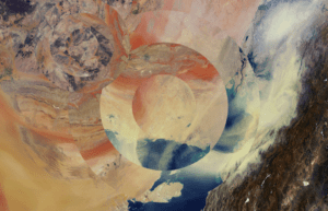
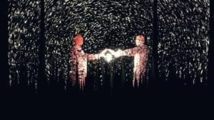
Another evolution of my definition of interaction is that people should be at the center in the process of interaction, instead of inputting code and leaving everything to the computer. Only in this way can this “conversation” between people and computer have a profound impact on the human being. The two projects serving as the inspiration for my final projects are Le Vent Nous Portera, and OKO. The inspiration I got is that a creative interactive process can be generated by putting those existing things, such as forests and image in NASA’s databases, into a new setting, setting interesting links with other things, and asking the audience to use an unusual way to operate a usual object is important. The first interactive project, Le Vent Nous Portera aligns with my definition of interaction, in terms of those criteria I mentioned above. For this interactive installation, participants move in a magnificent virtual forest, in which they are illuminated by luminous flying creatures following their position. Therefore, people are the decisive element for what the scenery of the forest would be like, and the space for the audience to experience is huge, through which they can create a sense of aesthetic by themselves. It also reminded me that the magnet can be a useful tool that we did not think about before for creating an interactive device. However, the project called OKO did not align with my definition of interaction. This is a puzzle game app, reconstructing the pictures from the NASA databases. This interactive app does not align with my definition of interaction. The reason is that by finishing the puzzle, nothing special was created by this conversation between the computer and people.

Le Vent Nous Portera – Magnificent forest by Alexander Letcius and Bulat Sharipov
OKO

After doing the midterm project and the research, my definition of interaction turns out that it is an informative conversation between several actors, in which human plays a central role. Inspirations, creations, and many other utilities can be generated, and the relationship between the actors should be clear.

References

The Art of Interactive Design, Crawford

Making Interactive Art: Set the Stage, Then Shut Up and Listen, Tom Igoe

Recitation 7: Processing Animation by Gloria Yixuan Liu

Recitation Exercise:

During this recitation, I modified my original work into an animation version, in which the color of the blocks and the stroke can be changed randomly, and more blocks would be added as you click the keyboard “Q”. I wanted to turn it into a more abstract way similar to Piet Mondrian’s painting Composition II in Red, Blue, and Yellow. The “keypressed” function is useful to turn this abstract work into a more lively genre, and it looks like the process of constructing buildings by adding blocks.

The most interesting functions that I used:

  1. for (int i=0;i<110;i+=100){

  strokeWeight(5);

  rect (random (width),random(height),random(200),random(200));

The for loop is a useful way to add patterns to my work and I can control how many patterns can be added.

  1. arc (500,500,30,30,0,1.5*PI);

the first and the second number is the position of the center of the arc, instead of the starting point. The last two numbers is the angle where the arc starts and ends. It would be useful if I use PI instead of numbers.

For the coefficient of PI, QUARTER can be useful.

  1. void keyPressed(){

 if (key==’q’||key==’Q’){

Use ‘ ‘ instead of “”.

Video:

Code:

void setup(){

  size (900,600);

background (#A8C1BC);

frameRate(10);

}

void draw(){

}

void keyPressed(){

  if (key==’q’||key==’Q’){

stroke (random(255));

strokeWeight(10);

rect (0,0,100,100);

rect (200,0,100,100);

stroke (random(100),random(100),random(255));

fill (random(100),random(100),random(255));

rect (400,0,100,100);

rect (600,0,100,100);

stroke(random(255),random(100),random(100));

rect (100,100,100,100);

rect (300,100,100,100);

rect (500,100,100,100);

fill (#459DD6);

rect (700,100,100,100);

stroke(random(100),random(255),random(100));

strokeWeight(50);

fill (random(100),random(255),random(100));

rect (0,200,100,100);

rect (200,200,100,100);

rect (400,200,100,100);

rect (600,200,100,100);

fill (#DEEBF5);

rect (100,300,100,100);

fill (#BCF734);

rect (300,300,100,100);

stroke(random(255),random(100),random(100));

strokeWeight(20);

rect (500,300,100,100);

rect (700,300,100,100);

rect (0, 400,100,100);

stroke(#090F03);

rect(200,400,100,100);

fill (random(100),random(255),random(100));

rect(400,400,100,100);

stroke (random(100),random(100),random(255));

rect (600,400,100,100);

stroke (#BCF734);

line (0,0,100,100);

stroke (random(100),random(100),random(255));

line (500,100,600,200);

stroke (random(255),random(100),random(100));

strokeWeight (10);

line (100,300,200,400);

stroke(#EA397A);

strokeWeight(5);

noFill();

arc(250,50,100,110,1.1*QUARTER_PI,5*QUARTER_PI);

arc(250,450,150,200,0,1.7*PI);

stroke (random(100),random(255),random(100));

fill(random(100),random(255),random(100));

arc(350,350,100,100 ,0, 3*QUARTER_PI);

arc(750,150,50,80,2,5*QUARTER_PI);

stroke (random(100),random(100),random(255));

strokeWeight(1);

fill(random(255),random(255),random(255));

arc(200,300,20,20,0,1.2*PI);

arc(250,350,60,80,1.2*PI, 2*PI);

arc(300,300,50,50,2*PI, 2.5*PI);

arc(450,240,150,150,0,PI);

arc (500,500,30,30,0,1.5*PI);

for (int i=0;i<110;i+=100){

  strokeWeight(5);

  rect (random (width),random(height),random(200),random(200));

}

    }

}

Homework:

For the first and the second step, it is important to define several variables at the beginning so that it won’t be messed up later. To use int or float can be decided after playing the animation and see whether the extent of the change of the position is proper. I used the method of defining a formula containing two variables to control the change of size of the circle.

At first, it did not work because I forgot to declare the equation “k=k+i” before the “if” and “else” section. 

For the third step, I learned how to change the color of the stroke smoothly according to the reference page. After setting the colorMode(HSB) in the setup section, I used the if and else function with a variable “l” to set a loop for color changing.

For the fourth step, I learned how to use the direction key on the keyboard to change the position of the subject, according to the reference page. First of all, it is important to make sure to set the “keycode” mode first. Then for the specific direction key, only the “==” works, instead of “=”.

Video:

Code:

int i=2;

float k=200;//////

float l=0;

int m;

int n;

void setup(){

  size(600,600);

   colorMode(HSB);//////

m=width/2;

n=height/2;

}

void draw(){

  background(255);

  noFill();

strokeWeight(15);

 ellipse(m,n,k,k);//STEP 1

 k=k+i;//////

 if (k< 100){

   i=2;

   k=k+i;

 }

 if (k>=300){

   i=-i;

   k=k+i;   //STEP 2

 }

 stroke(l,255,255);//////

 if (l<254){

   l++; //////

 }

   else{

   l=255-l;

 }          //STEP 3

}

void keyPressed(){

if (key == CODED){ //////

if (keyCode == UP){ //////

n = n – 20;

}

if (keyCode == DOWN){

n = n +20;

}

if (keyCode == LEFT){

m = m -20;

}

if (keyCode == RIGHT){

m = m +20;

}            //STEP 4

}

}

Midterm Project Documentation: Grass – Yixuan Liu -Eric Parren

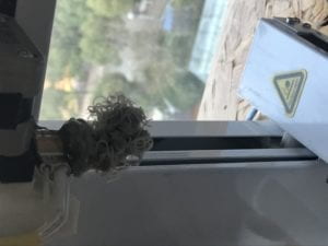
Our project is called Grass. The reason is that the shape of the optical fibre looks like a bunch of grass, while the grass can not only light up but also make some sounds of the standard notes when you touch it. However, there is some problem with the third note of E, making the third bunch of grass sounds like an electronic sound created by a DJ.

CONTEXT AND SIGNIFICANCE:

The previous research project was called Bedman. The shape of the bed can be re-grouped according to the way you want to use it, and it can store clothes, cook food, and stretch out wheels to be a means of transportation. This project gave me an inspiration for my midterm project that we can put the existing daily objects, such as the bed, into a brand-new format, which includes functions from other areas or can make the project be in a more aesthetic way. Therefore, we think about making a musical instrument in a creative way. The project called SUN which I have researched also gave me inspiration for the midterm project. By changing the position of the physical ball, the scenery of the sun is changed by the audience. Therefore, I think my midterm project can turn out to be something giving the audience chances to carry out creativity by themselves. These two projects also perfected my definition of interaction. It is not only a process of communication between different roles, but also that the outcomes of the communication should have a significant impact on the world or on each other, either in ways of utilization or aesthetics. Based on an existing project called Glowing Grass, our project can not only give out lights but also can create five standard musical notes. The uniqueness of our project is that our project is not only a piece of art which can give out lights through the optical fibre, but also a musical instrument on which you can play some simple songs. Our project is for everyone but would have more utility for children, since the light of the grass can stimulate their sense for light, and the sounds of the grass can help them to learn the standard musical notes.

CONCEPTION AND DESIGN:

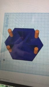
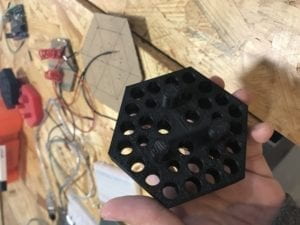
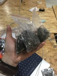
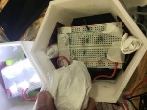
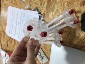
At first, we expected that users interact with our project by pushing or shaking the grass. Therefore, we tried to stick springs on each button, which is below the circuit board and surrounds the columns which connect the button and the circuit board. We expect that when people push the grass, the grass would lean, triggering the board’s leaning. The side of the board which goes down would press the button. However, we found out that the buttons are not sensitive enough, and you have to hold the grass and press it to turn on the button. Therefore, we put some conductive tape on the wall surrounding the circuit, and some conductive tape on each corner of the breadboard so that the user would not need to press too hard on the grass to make a sound. We used 30 LEDs, 5 speakers, 7 breadboards, 50 bunches of optical fibre, many transistors and resistors, 15 3D printed models, and 20 laser-cutting models. The criteria for selecting the materials was that they should be flexible since we need to make a lot of adjustments to perfect our project. Some of our material’s elasticity has to be suitable so that it would be easy for people to push the grass to make a sound, but also that the board can go back to where it was. What is more, we also used the optical fibre which can conduct the light and shape some lighting spots on the top. We thought about using the iron springs and napkin to fix the circuit board. However, they were rejected, because the first one was too hard, making the board hard to move, while the latter was too soft, and the board was hard to go back to the original position.

FABRICATION AND PRODUCTION:

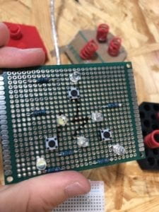
The first significant process was that we used the conductive tape (which was suggested by Nick) to replace the buttons. Since the conductive tape formed a magnet circle, causing the circuit to have the opposite reaction from what it is supposed to be, we changed the circle of conductive tape into two pieces of conductive tape. The second significant process was that we designed different versions of 3D printing models so that we can make adjustments in terms of the circuit. However, we failed for more than 20 times for printing those models, each of which costs about 2 hours to print. The third significant process was that we decreased the number of LEDs so that the light can be strong enough. The fourth significant process was how we decided what kind of player to use. At first, we thought about using the Audacity to play the mp3 file, but the volume was too low. Then we used the SD card, but the sound was still too low. Then we used 5 buzzers instead, the sound was really jarring. However, since the sounds were clear and loud, we kept using the buzzers. During the User Testing Session, almost everyone pointed out that they had to press really hard to make the sound, and the grass will not go back to its original place after that. We used Nick’s suggestion that we put conductive around the breadboard, so that we don’t need to use the button. It was really effective, although at first the circle of conductive tape formed a magnet.

Draft

Daily Failure

Magnet Circle- Credit to Sheldon

9 LEDs
Circuit for 9 LEDs


Code- by Sheldon

CONCLUSION:

The original goal of our project is to make a glowing musical instrument. Our project aligns with my definition of interaction that it creates a conversation between the audience and the device, and has some significant utility such as playing some simple songs and creating a sense of aesthetics. However, it does not align with my definition of interaction that this conversation was not continuous enough since the conductive tape was not sensitive enough and the sound was jarring. Ultimately, the audience interacted with our project by pushing the grass to make the sound, and the optical fibre also gave out lights. However, they were confused about which direction should they push the grass in to make the sound. The reason is that we changed the conductive tape circle into two pieces of conductive tapes to avoid forming a magnet, but finally removed one piece from the two, leaving the other piece which has higher conductivity. If I had more time, I would put more conductive tapes on the inside of the wall of the instrument, but also make sure that they are not connected to each other, so that whichever direction you push the grass in, there can always be a sound. What is more, we would fix the annoying sound for note E, and maybe figure out how to use an SD card to play the sounds of harps. We would also add more bunches of grasses instead of having only 5 so that we can play some more complicated songs, What is more, we would also fix the code so that two different notes can be played at the same time, which can be used to play some chords.

I learned from our failure that we should have focused on only one aspect, such as how to make the project a perfect musical instrument or how to make it give out lights in a more aesthetic way, instead of focusing on fusing different functions together while achieving nothing ultimately. I would take away from our accomplishments that always have some backed up plans, and try to use some materials which are so daily that they seem to have no connection with this project (for example, we used the wires to make some springs to replace those iron springs, and used the napkins to fix the position of the breadboard). Generally, I learned that never be restricted by the prototype online if you have, since the materials we have and the creation of the project are not exactly the same with the prototype. It is always important to think about what to do in reality and pay attention to taking the audience’s advice.

Napkin Support
Wire Spring

Recitation 6: Processing Basics by Yixuan Liu

Motif:

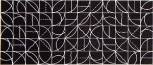
FORMULA 15 by Sol LeWitt

The image I chose is called Formula 15 by Sol LeWitt. The reason why I chose this image was that the combination of those regular and standard shapes and lines created a sense of aesthetics, and it may also be easy to draw with the functions we’ve learned in Processing.

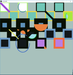
Based on the motif, I want my image to be more variable for both color and shape compared with what it used to be. Therefore, I changed the color and the weight of different rectangles, and add not only straight lines but also arcs inside of the rectangles.

My final creation links to the motif in the way that the basic structure is that same, which contains many rectangles of the same size, and many curves and lines inside. However, there are some differences between mine and the motif. The first is that the motif is black-and-white, while mine is more colorful, since different rectangles are filled with different colors, and the color of the strokes are different as well. The second difference is that the rectangles in the motif are of the same weight, while I changed the weight of the strokes in my image. The third difference is that the lines and curves in the motif all start from a corner of a rectangle then end at another corner of a rectangle. In my image, I added some arcs apart from lines to make the whole image more abstract and in a more pop-arted way.

I don’t think drawing in Processing is a good way of realizing my design. The reason is that the shaped drawn by Processing are in a fixed way, and it is really hard to add varieties and irregular patterns. It is also troublesome since you have to think about the position of each point in the axis, which can make the process of drawing inefficient.

Code:

size (800,800);

background (#A8C1BC);

stroke (#ADF074);

strokeWeight(10);

rect (0,0,100,100);

rect (200,0,100,100);

stroke (#090F03);

fill (#70C6B6);

rect (400,0,100,100);

rect (600,0,100,100);

stroke(#F2D73B);

rect (100,100,100,100);

rect (300,100,100,100);

rect (500,100,100,100);

fill (#A6EA40);

rect (700,100,100,100);

stroke(#090F03);

strokeWeight(50);

fill (#5E92B9);

rect (0,200,100,100);

rect (200,200,100,100);

rect (400,200,100,100);

rect (600,200,100,100);

fill (#DEEBF5);

rect (100,300,100,100);

fill (#13171A);

rect (300,300,100,100);

stroke(#709CC6);

strokeWeight(20);

rect (500,300,100,100);

rect (700,300,100,100);

rect (0, 400,100,100);

stroke(#090F03);

rect(200,400,100,100);

fill (#BA7EE3);

rect(400,400,100,100);

stroke (#F26C3B);

rect (600,400,100,100);

stroke (#9B49D3);

line (0,0,100,100);

stroke (#081415);

line (500,100,600,200);

stroke (#E5E862);

strokeWeight (10);

line (100,300,200,400);

stroke(#2856C6);

strokeWeight(5);

noFill();

arc(250,50,100,110,1.1*QUARTER_PI,5*QUARTER_PI);

arc(250,450,150,200,0,1.7*PI);

stroke (#28C659);

fill(#9DDCE8);

arc(350,350,100,100 ,0, 3*QUARTER_PI);

arc(750,150,50,80,2,5*QUARTER_PI);

stroke (#E5AE56);

strokeWeight(1);

fill(#EA8140);

arc(200,300,20,20,0,1.2*PI);

arc(250,350,60,80,1.2*PI, 2*PI);

arc(300,300,50,50,2*PI, 2.5*PI);

arc(450,240,150,150,0,PI);

arc (500,500,30,30,0,1.5*PI);

Sketch:

Sketch