INTM-SHU 101 – 005 Week 5 Documentation by Sam Li

Step 1: Build the stepper motor circuit

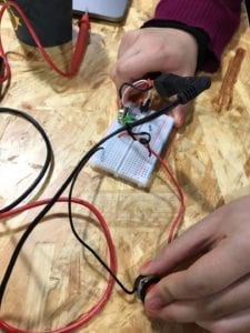
In the recitation, I firstly built a circuit that controls the stepper motor. I used an arduino board, a H-Bridge, an external power source, and the stepper motor in this circuit. When the circuit is finished, codes uploaded and connected to power source, I could observe how the stepper motor revolves in divergent directions alternately.

Step 2: Control rotation with a potentiometer

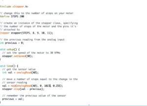
In step 2, I added a potentiometer to the circuit as well as changing the code, so that I can control the direction of the stepper motor as it revolves. The potentiometer is connected to A0 pin on the arduino board, providing analog inputs to the arduino board. After the circuit was completed, I also revised the code. I added in an integer for the A0 pin. Then, I also mapped the value from the analog input towards the output, i.e., from a range of 0 to 1023 towards a range of 0 and 255.

When I controlled the potentiometer, I could change the direction of how the motor rotated by changing the direction as I rotated the potentiometer.

Modified Codes:

Step 3: Build a drawing machine

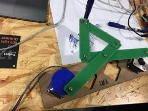
After I finished my previous 2 circuits, I joined my partner Kathy for the drawing machine task. Kathy and I placed our stepper motors on the motor holder, and we also assembled other components of the machine, including the short and long arms, as well as the motor coupling. We connected both our motors to our arduino boards, place the pen into the machine, and started to control our own potentiometers. It was fascinated to see how different combinations of inputs from my arduino board and from Kathy’s arduino board created unique movements of the pen. The machine created different patterns and lines combining the controls from both motors.

Question 1: What kind of machines would you be interested in building?

I am interested in building a machine embedded in a museum or gallery space. The machine can sense the changes of people’s emotions through facial recognition techniques. By sensing the emotional states of the viewers, the machine can further facilitates an interaction and reciprocal dialogue between the viewer and any piece of art objects. For instance, the machine might be able to project any kind of digital images upon physical art pieces at real time, reflecting or responding to the viewer’s emotional state. The machine bridges the physical but static art space and the digital art space, augmenting the experience one can get when appreciating traditional art objects.

Question 2: Choose an art installation mentioned in the reading ART + Science NOW, Stephen Wilson (Kinetics chapter). Post your thoughts about it and make a comparison with the work you did during this recitation. How do you think that the artist selected those specific actuators for his project?

Daniel Rozin’s Mechanical Mirrors project from the ART + Science NOW kinetics chapter captures my attention the most. Rozin’s piece uses camera to capture images of the viewers of the piece, and transforms images into grayscale pixels. Signals of pixels triggered responses on the actuators, the servo motors. The motors drive changes of small wooden pieces and therefore construct reflective images of the viewers. The artist picked servo motors because they are a kind of rotary actuators that move in angular directions, and they are also small and light-weighted.

The project I made during the recitation is a painting machine, composed with two stepper motors as actuators. The stepper motors enabled the machine to control the pen’s movement in parallel direction. In contrast, in Rozin’s Mechanical Mirrors piece, servo motors could flip wooden pieces over in 360 degrees and construct images in wooden pixels. The artist choose servo motors to achieve this task. 

INTM-SHU 101 – 005 Week 4 Documentation by Sam Li

Week 4 documentation blog

1.My definition of “interaction”

I define interaction as the reciprocal process in which two or more actors actively signal out information to each other, receive and process information, and then give out responses in return. To me, interaction is not a purely mechanical process, but instead a creative process that constructs meaningful conversations between human, human and environment, or human and computers. My definition always involves the participation of human, as I think the essence of interaction is based upon human thinking and human experiences.

2. Project examples: 

My understanding of interaction is especially shaped by two projects, one is the “Eye writer” project by Zack Lieberman and the other is the “Expressive Tactile Controls” project by Hayeon Hwang. The “Eye writer” project enables me to think about interaction in the sense that it is not as simple as human interact with computers or artificial machines; but instead, the interaction between human and computer especially should better support and augment human capacity to express oneself and communicate to the outer world. Lieberman’s project was able to help the Graffiti artist with disability communicate his ideas out and transform threads of human thoughts into tangible gratifies projected on giant walls. However, Lieberman’s project mostly facilitates the interaction between the Graffiti artist and the eye writer device. The audience of such Graffiti artworks only engaged in less degree of interaction. When the audience interact with the Graffitis, they simply observe how projection of graffitis changes, but those changes do not respond to the reaction of the audiences. The audiences mostly interact with graffiti pieces with their eyes.

My understanding of interaction was further shaped by Hwang’s “Expressive Tactile Controls” project, which embodies greater level of interaction for any audiences. Similar as the “Eye writer” project, Hwang’s project augments humanity, as it simulates and expresses different human emotions through machines. Humans interact with the machine not for enjoying the mechanical process of pushing a button, but we want to enjoy and experience the emotions of human beings as embodied in these buttons. Unlike audiences of the graffitis who simply observe and react to the changes of graffiti projection, audiences interact with the “Expressive Tactile Controls” project on multiple dimensions. A person interacting with Hwang’s project touches it with his or her hands, observes visible changes, possibly hears any kind of sound created by the buttons, and reacts to this interactive process. The installation also receives signals from the human, processes signals, and gives out different responses through the movement of buttons. Human participants engage in this interactive process by multiple senses.

3. How my understanding of interaction has evolved?

From week 1 to week 4, my understanding of interaction evolve from one about two actors listening, thinking, and speaking with each other towards one that involves meaningful conversations between human actors, artificial or non-human objects, as well as the wider social context. Our first week reading about interactivity helps me see interaction as a reciprocal process. One actor speaking or giving out some signals is not enough, but interaction must also involve the process of sense-making and the other actors responding. It’s about dialogues between these human or non-human agents. The second week’s Introduction to Physical Computing chapter by Igoe and O’sullivan and Manovich’s The Language of New Media lay emphasis on the role of computational thinking and artificial intelligence in the process of interaction. Some might argue that interaction is increasingly about how computers transform the way we see, interpret, and make sense of both the virtual and physical world. However, I still believe strongly that a meaningful interaction should always involve and serve to augment human connection and communication. Interaction, even with the support of computers, should serve to better facilitate how humans connect and communicate with each other, with our wider social context, or with other artificial or non-human objects.

The “Making Interactive Art”  blog post resonates with me strongly. The article specifically discusses the purpose of making interactive artwork is not about the creator making any kinds of assertive statements out there. Instead, the interactive artworks are meant to be platforms and contexts facilitating open dialogues between the creator, the audience, the object, and the contextual environment. When building some prototype or machine, it’s easy to leave out the context and focus on the product itself. But in actual use of products, it must be embedded in various kinds of social contexts, whether in the home setting, at a primary school, or in a public square. And any interaction should be contextual. It’s not simply a user interacting with the product, but also with the outer environment where the product or artwork is situated in. The reciprocal process of listening, thinking, and speaking should thus be experiential, expressive, sensual, and inherently creative; not mechanical or simply repetitive.

4. Our Group Project: “A New Dimension of Braille”
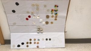
The title of our prototype and performance is called “A New Dimension of Braille”. The idea initially derived from Lieberman’s “Eye writer” project. Inspired by Lieberman’s project that enables a disabled graffiti artist to create artworks, our initial motivation was to create something that supports how a disabled person interact with his or her surroundings. Our teammate Kathy came up with the idea that we could possibly do something for people with visual disability. The team discussed that in the year of 2119, most of the interaction on earth might become entirely digital on flat screens. However, for people with disability, digitization might pose huge challenge for them to interact with others or the surroundings. While a person with good eyesight can easily see the changes on screens, a blind person could find it hard to navigate their lives around.

Further responding to some of the project examples we’ve discovered about interaction, such as the “Expressive Tactile Control” project I’ve found, we came up with the idea to augment language into something touchable and sensible, so that people with visual disability could interact with languages and words with their hands and ears. We used cardboards to create a prototype machine, which resembles a flat digital screens. Unlike screens or tablets we have in our world today, our machine could augment real textures and materials from the screen, possibly through some kinds of projection or AR/VR technologies. For instance, the device could be used for a child with visual disability to learn more about language beyond just braille. When a child was learning a word through the device, different kinds of textures or materials could be projected out for the child to touch upon. The interaction between the child and the device does not stay on verbal communication, but also exchanging information and meanings through tactile senses. The device can potentially have wider use in augmenting different kinds of textures, not only for people with visual disability, but others who have the needs to understand and feel different kinds of materials. For instance, a fashion designer might find this device extremely useful, as it can help him/her efficiently figure out the most suitable material for a clothing piece. 

The project represents my definition of interaction because the device serves to facilitate how humans, in this case for people with visual disability, better interact with the outer world. The interaction engages senses on multiple dimensions, as well as addressing a problem faced by people with visual disability have been facing in the age of digitization and physical computing. 
INTM-SHU 101 – 005 Week 3 Documentation by Sam Li

Week 3 Documentation Blog

Recitation Exercise:

For this recitation exercise, please work with a partner. Choose one of the sensors listed below and read about what it is and how it performs. Once you have picked a sensor, build a circuit that integrates this sensor with your Arduino.

  1. Use the data (input) from your sensor to drive an output (Servo-motor, LEDs, Buzzer, etc.).
  2. Document the finished circuit and your interaction with it.
  3. In addition, draw a diagram of how all the components are connected and add this to your documentation. If you finish your circuit early, swap out the sensor in your circuit with a different sensor. Please cite any sources you reference to do this exercise.
  4. For these circuits, think back to the lessons from class, such as how to map() an analog input, as well as how to set an analog output with an analog input. This can be seen in the example AnalogInOutSerial (Arduino>File>Examples>0.3Analog>AnalogInOutSerial).

Recitation Documentation:

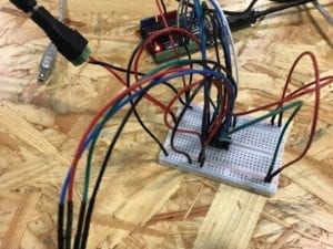
In the recitation session, my partner and I created a circuit using moisture sensor to detect moisture level and LED to indicate the differences in moisture level.

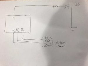
We firstly connected the moisture circuit to the arduino board, using a red wire to connect 5V pin to the VCC pin, connecting the arduino GND pin to the sensor’s GND pin, and connected the A0 pin on arduino to sensor’s SIG (signal pin). Now, a circuit of the moisture sensor is finished. When we placed the sensor deeper into the water ,the value in serial monitor goes from 0 to about 600. When we gradually took the sensor out of the water, the value drops and eventually became 0.

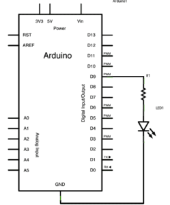
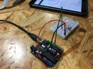
Then, we connected pin 9 on arduino board to a resistor then a LED on the breadboard, as well as using another wire to connect the LED to the ground. Below is a schematics of our circuit.

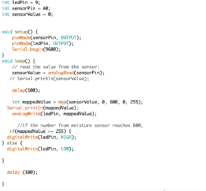
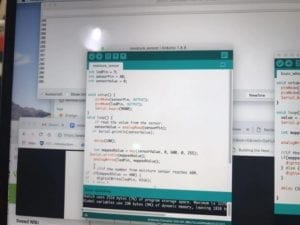
Based on the code for the moisture sensor, we added in a category for the LED, set its pin mode. Then we mapped the value from the sensor to the LED. Through just testing the sensor, we noticed that the maximum value is approximately 600 and the minimum value is 0. Thus, we used the “mappedValue ()” code to map sensor value to the LED value, in order that the LED’s brightness changes as the moisture level changes.

When we uploaded the code and put out the serial monitor, we observed that as the moisture sensor is put deeper into the water, the value shown in serial monitor increased from 0 to about 255 (the value that has been mapped to a range of 0 and 255), and the LED kept become brighter. When we gradually took the sensor out of the water and tried to dry it up, the LED became darker and darker, and eventually off, when the moisture level became 0.

(Later, we also added codes that say when the sensor detects the maximum moisture value, the LED lights up. Otherwise, the LED is off. However, we did not have enough time to test out this function.)

Question 1: What did you intend to assemble in the recitation exercise? If your sensor/actuator combination were to be used for pragmatic purposes, who would use it, why would they use it, and how could it be used?

When building the circuit, my partner and I intended to use the moisture sensor to detect different moisture level and use different brightness of LEDs to indicate different moisture levels.

For instance, gardeners or anyone growing their own plants might want to use this sensor/actuator combination. They can use it to detect the moisture level inside the soil, making sure that they are not watering the plants too much or too little. If the moisture level exceed a certain threshold, the LED light will be on, indicating that they’ve put too much water. If the water level is below a certain threshold, another LED light can also be on, suggesting that they should water more. The product can be used by placing the censor into the soil, and possibly that the LEDs can be installed in some kind of well-designed boxes. If the plants are contained by flowerpots, the sensors and LEDs can be embedded in the flowerpots. The plant growers will see moisture levels of the soil through embedded LEDs suggesting not enough water or too much water.

Question 2: Code is often compared to following a recipe or tutorial.  Why do you think that is?

A recipe or tutorial provides detailed information about the necessary ingredients or materials to make something. Besides, they also provides step-by-step guidance about the tangible steps needed to assemble ingredients into a man-made outcome, a dish or a product. Similarly, code provides necessary information about the necessary inputs needed in order to achieve some kinds of outputs. Codes also involve the necessary steps or procedures to create that output.

Question 3: In Language of New Media, Manovich describes the influence of computers on new media. In what ways do you believe the computer influences our human behaviors?

In the numerical representation section, Manovich argues that the development of computers fundamentally challenged the tradition that digital codes were used as tools to create art or media forms, but instead media or art became tools to represent the language of computers. Such an argument might also be applied to the understandings and behaviors of humans. We used to think that human beings created the language, logics, and behaviors of computer; however, as computers became more automated and intelligent, in many ways, human behaviors and thinking have become the ramification of computational language and algorithmic logics. For instance, when I make a decision of which movie to watch, I use my digital devices to look at the scores or ratings people give to those movies, instead of basing my decision on other sources of information.

INTM-SHU 101 – 005 Week 2 Documentation by Sam Li

Circuit 1: Fade

Fade LED Circuit
Fade LED Circuit
Fade LED Circuit

Process:

  • First, we put the LED light and the 220 ohm resistor on the breadboard. We also connected the shorter leg of the LED to the ground through a wire on the breadboard.
  • Second, we used another wire to connect the ground rail on the breadboard to the ground pin on arduino board. We also used a wire to connect the button 5V pin to the breadboard, serving as a powersource.
  • Then, we found the “fade” code from examples, connected the arduino board to my laptop, checked if we’ve chosen the right right port and board. We uploaded the “fade” code.

Result and learning:

  • Result: The LED was originally on when we connected it to the 5V power source. When we uploaded the code to arduino, after a while, the LED started to fade regularly.

Circuit 2: toneMelody

Schematics for toneMelody
toneMelody Circuit
toneMelody Circuit

Process:

  • First, we put the buzzer on the breadboard.
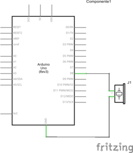
  • Second, we used a wire to connect the positive end of buzzer to upper pin 8, and a wire to connect the negative end of buzzer to upper pin ground.
  • Third, we connected the arduino board to my laptop, uploaded the “toneMelody” example code

Result and learning:

  • Result: the buzzer started to create its melody sound after uploading the code, as seen in the video below

Circuit 3: Speed Game

Speed Game Schematics
Speed Game Diagram
Serial Monitor when playing the game

Process:

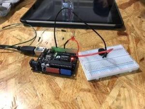
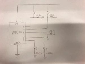
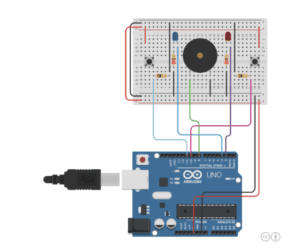
  • First, we placed two switches on the breadboard, respectively connected to two 10k ohm resistors.
  • We placed two LED lights, respectively connected to two 220 ohm resistors through the breadboard.
  • We placed a buzzer at the center of the breadboard
  • Then, we used wires to connect the arduino 5V power source pin to the breadboard and another wire connecting breadboard to the bottom ground pin, and connecting the positive rails on two sides.
  • We used wire to connect pin 11 and pin 10 respectively to the two switches,  and used two wires to connect the 10k resistors to the ground.
  • We connected pin 3 and pin 2 respectively to the two LEDs, and then linking the two 220 ohm resistors to the ground, respectively.
  • Then, we connected the arduino board to the laptop, and uploading the speed game code.

Result and learning:

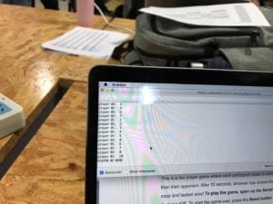
  • Result: We opened the serial monitor as we tested out the circuit. After we pressed the reset button, we saw on the serial board showing instruction about when to begin, by “Ready? Go”. My partner and I respectively pressed our buttons, as fast as we could. Eventually my partner won the game, with the LED lights turning on, the buzzer creating a melody, and the serial monitor showing both how many times we each pressed and the result of the game.
  • Learning: I learned from professors that the 220 ohm resistor is connected to the LED to prevent the LED from breaking; the 10K ohm resistor is connected to the switch to give out signal. I also learned that the serial monitor allows us to check and monitor the interactive process. If any parts of the circuits goes wrong and we are not able to see from the appearance of the circuit, we can probably use the serial monitor to find out which part goes wrong.

Question 1:

Reflect how you use technology in your daily life and on the circuits you just built. Use the text Physical Computing and your own observations to define interaction.

The Physical Computing text argues that physical computing creates an interaction and dialogue between the physical and virtual world. Similar as what’s stated in the article about interactivity, the authors of the Physical Computing text argues that interaction is an iterative process that involves listening, thinking, and listening of two actors. The interaction between human and computer involves how humans give out signals (inputs), how computers listen and think (processing), and how computer speak out with computational outputs.

In my everyday life, my interaction with my laptop is the most salient example of human-computer interaction. When I press certain keys on my laptop, my computer receives my inputs, it thinks about/processes what information I gives out, and then it speaks with media output such as letters showing up on my computer screen.

The circuit of fade LED light we built on the second recitation also involves such an interaction. As I upload the arduino code to my arduino board, the device receives my message and listens; it thinks about what command or messages I have sent out, telling it to control the fading of a LED light. Then it speaks out with the output, which controls the LED to fade regularly.

Question 2:

If you have 100,000 LEDs of any brightness and color at your disposal, what would you make and where would you put it?

If I have 100,000 of such LEDs, I want to create a giant installation that creates interaction between human emotions and the LED lights. When an audience stands in front of the installation, their facial expression and body movements will be captured by sensors and video cameras. If sensors detect an audience to be in happy mood, the LED lights will light up in warm colors and configure the shape of a smiley face. If the the audience was sensed to be in a bad mood, the LEDs will change into cold colors and create the shape of a sad face.

I want to place this installation at an enclosed space but located at a busy area of the city center, for instance, the West Nanjing Road in Shanghai or Time Square in New York. I hope the installation will help people take a break from the bustle and hustle of everyday city life, and become more mindful of one’s inner emotional state.

INTM-SHU 101 – 005 Week 1 Documentation by Sam Li

-Part I. Solder an arcade button

Our group first soldered an arcade button at the soldering station. We used tin and the soldering machine to stabilize wires on both sides of an arcade button, so that the button can be connect with other parts of the circuit. As we were melting the tin, a problem occurred that our soldering machine was not able to melt the tin. Our teaching fellow told us that the problem occured because our soldering machine was oxidized. We changed another soldering machine, and the problem was resolved.

-Part II. Build the circuits

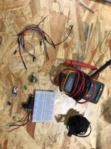
Basic components:

  • Breadboard: A device for connecting multiple components of a circuit
  • A LM7805 Voltage regulator: a device for maintaining a constant voltage level
  • An arcade button: a switch that controls the flow of electricity by turning it on and off
  • A 100nF capacitor: capacitor stores energy
  • A 12 volt power supply: the source of power
  • A barrel jack: connects power supply
  • Several jumper cables: connects multiple components in the circuit and enable electricity to pass through
  • A buzzer: an audio signalizing device. When the user presses the button, the buzzer will create signal of sound
  • A 220 ohm resistor: an electric component that creates electrical resistance in a circuit
  • A LED: a light-emitting diodes, serving as a light source for the user
  • a 10K ohm variable resistor: a device that can be used to adjust the resistance in the circuit, changing the volume of currents passing through

Circuit 1: Door Bell

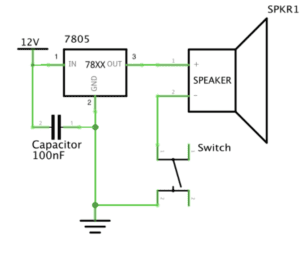
Schematics of circuit 1
  • Components: a breadboard, a LM7805 Voltage regulator, an arcade button, a 100nF capacitor, a 12 volt power supply, a barrel jack, several jumper cables, and a buzzer
  • Process:
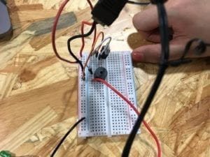
    • To build the circuit for doorbell, we put the positive leg (red leg) of power source to the first hole on row 1 and the negative (black) leg to the negative rail (in order that the black wire is connected to the ground and that electricity flows through the divide between leftist columns and middle rows).
    • Second, we use a wire to connect the positive leg of power source to row 1, so that the electricity can go from the left-side columns to the rows in the middle. A voltage regulator and a capacitor are connected in parallel. We used an extra wire to connect the middle leg on voltage regulator to the ground.
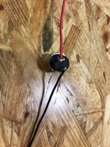
    • We then connected the “out” leg of voltage regulator to one leg of our buzzer, using an extra wire. The other leg of the speaker is connected to our arcade button.
    • The arcade button is connected back to the negative column on the left side, so that the circuit is closed.
  • Results and Key learning:
    • After building the circuit, we connect our power source to an outlet. As we press the arcade button, the buzzer creates a “beep” sound.
    • I learned from this process that electricity goes in vertical direction in the leftist two columns and it goes in parallel direction across the rows in the middle.

Circuit 2: Lamp

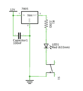
Schematics of circuit 2
  • Components: a breadboard, a LM7805 Voltage regulator, an arcade button, a 100nF capacitor, a 12 volt power supply, a barrel jack, several jumper cables, a 220 ohm resistor, and a LED
  • Process:
    • We got two resistors for the circuit. In order to pick the 220 ohm resistor, we used the multimeter to test out its resistance.
    • We firstly unplug our power source from the outlet before making changes to the circuit. To build the circuit for our lamp, we took out the buzzer and wires connected to it.
    • Upon unchanged components of the previous doorbell circuit, we use an extra wire to connect “out” leg of the voltage regulator and row 9.
    • Then we put one leg of the 220 resistor on row 9 and the other leg on row 12.
    • One leg of the LED light was connected to row 12 and the other leg on row 18.
    • One leg of the arcade button is connected to row 18, and the other leg of it is connected to the ground.
  • Results and Key learning
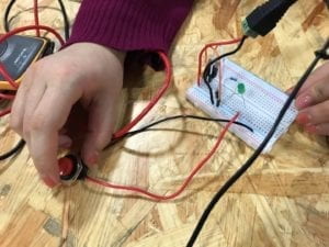
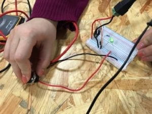
    • We connect our power source to the power outlet. When we push the arcade button, the LED light is on.
    • Multimeter is useful for testing the ohm of our resistor.

Circuit 3: Dimmable Lamp

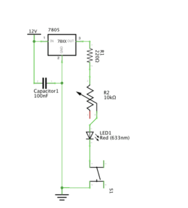
Schematic of circuit 3
  • Components: a breadboard, a LM7805 Voltage regulator, an arcade button, a 100nF capacitor, a 12 volt power supply, a barrel jack, several jumper cables, a 220 ohm resistor, a 10K ohm variable resistor, and a LED
  • Process:
    • We first unplug our power source from the outlet.
    • Upon the previous lamp circuit, we added in a variable resistor between the 220 ohm resistor and the LED.
    • The middle leg of variable resistor is connected to the 220 resistor while the leftist leg (looking from the raised side of variable resistor) is connected to the LED.
  • Results and key learnings
    • We plug in our power source to the outlet, then press the arcade button. The LED light is on when pressing the button. When we turn the variable resistor, we see that the LED light goes dimmer.
    • We learned that the variable resistor could be very useful in controlling the volume of electricity passing through, and thus the lightness of LEDs.

Question 1:

After reading The Art of Interactive Design, in what way do you think that the circuits you built today include interactivity? Please explain your answer.

In response to The Art of Interactive Design, my circuits include interactivity for the following reasons. First, there are two actors involved in the process of interactivity, namely the circuits and their users. Second, the two actors interact in iterative manners. They listen, think, and speak in turns. For instance, when the user interacts with my lamp circuit, the user sees the button. He/she receives the signal that he/she can anticipate a response when pressing the button. The user presses the button. The circuit listens to the signal, it thinks and responses with letting the current go through. Thus, the light will be on.

Question 2:

How can Interaction Design and Physical Computing be used to create Interactive Art? You can reference Zack Lieberman’s video or any other artist that you know .

As shown in Zack Lieberman’s video, creators like Zack uses physical computing to write softwares that process inputs from the physical world and transform them into creative outputs in another form. For instance, in the eye writer project, Zack wrote a software that tracks the movement of human eyeballs to create graffiti. His software and installation then projected patterns of graffiti on huge walls. Interaction happens when the graffiti creator interact with the machine tracking eyeball movements. The audience also interacts with the “Eye Writer” when they receive and react to projected graffiti patterns.