Recitation 4: Drawing Machines by Yiwen Hu

Overview

Based on the circuit building techniques we have learnt and practices so far, the exercise this time involves more complex circuit building skills and new components— stepper motor and integrated circuit H-bridge are introduced to produce interesting interaction. The project we are trying to make in the exercise is an automatically drawing pencil whose movements are mainly directed by two stepper motors.  We work individually in the first two steps to build up the supporting framework before working in pairs to build up the whole device.

Materials:

For Steps 1 and 2

1 * 42STH33-0404AC stepper motor
1 * L293D ic chip
1 * power jack
1 * 12 VDC power supply
1 * Arduino kit and its contents

For Step 3

2 * Laser-cut short arms
2 * Laser-cut long arms
1* Laser-cut motor holder
2 * 3D printed motor coupling
5 * Paper Fasteners
1 * Pen that fits the laser-cut mechanisms
Paper

Step 1: Build the circuit
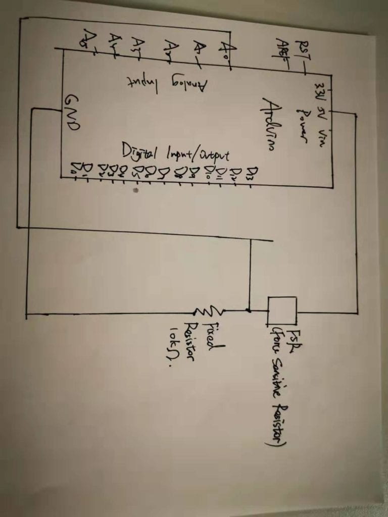
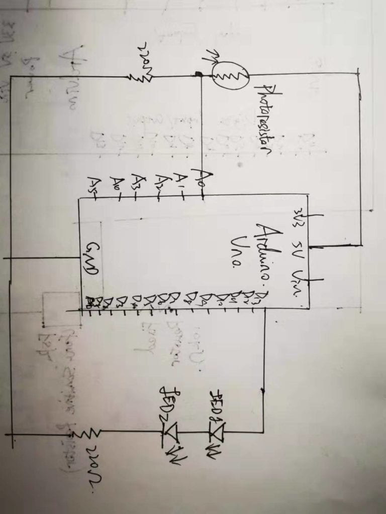
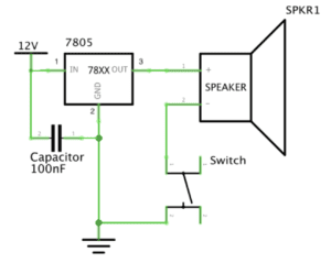
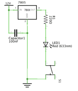
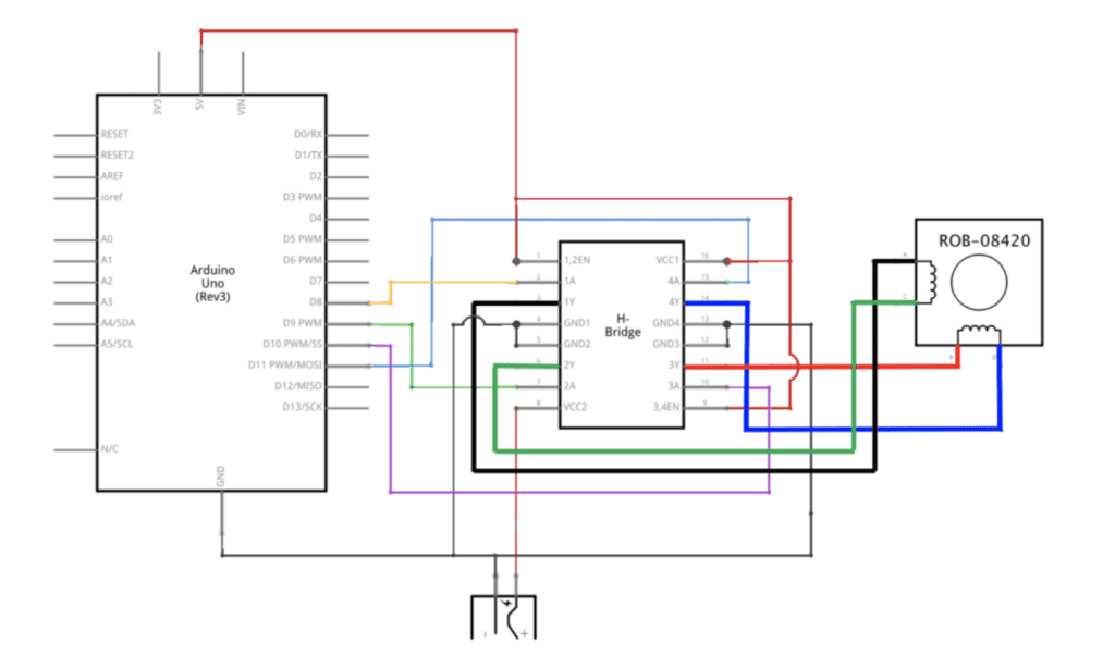
Schematic

Process

I built the H-bridge first, an integrated circuit that has many transistors inside which can reverse the polarity of the motor to enable the motor to run forward or backwards. The type we used is L293D. The schematics looked confusing to me at first due to its complex structure, but as I studied it in detail and also with the help of learning assistant later (Great thanks to Jessia Chon and Eszter Vigh! ) I figured out the structure and working mechanism of it. The H-bridge could be divided into four identical electronic parts that work together to take in inputs (power) and generate outputs. VCC2 is for the connection of external battery to supply power to the stepper motor. The four feet the stepper motor has corresponds to the four divided part, each containing one power supply, one pin connection to the Arduino, one connection to the stepper motor and one connected to the ground. Each part’s structure is just the basic circuit structure we’ve been building in class. It became easier to build the circuits after I figured out how it worked. 
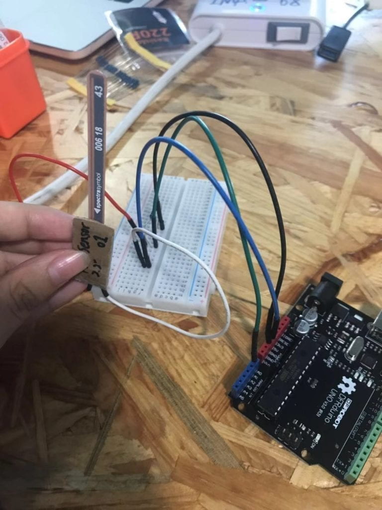
Here’s my work!

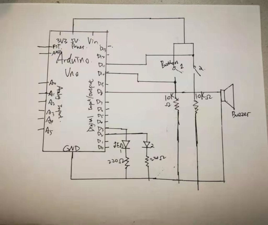
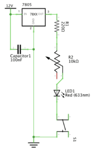
Step 2: Control rotation with a potentiometer

Process

This step was built on the first step and was quite simple. I just added a potentiometer to the circuit, with the middle feet connected to the pin and the two feet on the opposite respectively connected to the power supply and ground. In terms of the code, I added map() function to the existing one and adjusted the number of steps within the code to 200 since the stepper motor is a 200 stepper motor. 

Step 3: Build a Drawing Machine!

Process

After building an adjustable stepper motor using H-bridge and potentiometer individually, I worked in pairs with Feifan Li who had also finished step 1 and 2. The main task now was to combine our work together and establish the rest of the drawing machine to make it work! 

The first thing we did was to fix the stepper motor by the motor holder and fixed them together with a fastener. Then we installed the laser-cut long arms and short arms onto the motors and fixed the pencil between the arms. In the end we put a piece of paper under the pencil and piled up some papers under the white paper to ensure its contact with the pencil. After the device had been built up we did some checking work to ensure accuracy (burning computer was too costly!) before connecting it with our computers. 

It finally worked, but one motor seemed to be insensitive to movement and led to a drawing completed not so smoothly. We checked the through the code and circuits and found no problem. We though this was because the rotating disc was too rough for the motor to drive. But in general, we got the machine working!

step3video (I don’t know why it’s in this form…)

Response to Questions:

  1. What kind of machines would you be interested in building?Add a reflection about the use of actuators, the digital manipulation of art, and the creative process to your blog post.

I’d like to build an interactive musical instrument that is responsive to humans’ emotions. Specifically, the musical machine will scan the person in front of it and the underlying algorithms will examine the person’s face in detail to recognize his/her emotions by analyzing the facial expressions of that person. And it will produce corresponding music upon its interpretation of the person’s emotions (for example produce happy music when the person is upsetting) The actuator serves as a tool to respond to the users’ emotions and produce corresponding music based on the machines’ analysis. In this way it can be thought of a machine brain, or a purposeful digital creature that could understand and respond to a user to create interaction. The actuators are like our senses, and the underlying mechanisms are the thinking process of the respondent and the music/digital manipulation of art is an output. All are put together to create a conversation. 

2. Choose an art installation mentioned in the reading ART + Science NOW, Stephen Wilson (Kinetics chapter). Post your thoughts about it and make a comparison with the work you did during this recitation. How do you think that the artist selected those specific actuators for his project?

The Blanket Project by Canadian artist Nicholas Stedman surprises me with its integration of intelligence. Instead of waiting for input as what most projects I’ve seen and done so far, it takes initiatives to search people and therefore “consciously” search for interaction. It’s also responsive to input, which is people’s movement and adjusts its output correspondingly. The actuator it uses is tactile sensors. In comparison, the drawing machines we did this recitation was more mechanic. The input required some manual effort and the output is not within our control. It’s more like an effect we’ve made on the machine, instead of a responsive object that suits our need, like the blanket robotics.  I think the artist selected the tactile sensor from daily experience. When we are sitting on the blanket, the main contact between ourselves and the blanket is the body part. So there will definitely more information the computer can get from interpreting our body movements. And in that sense, the tactile sensor is the best choice.

Group Research Project Reflection- Yiwen Hu

My own definition of interaction is an iterative conversation between two or more actors and can be broken down into input, process and output. In addition, interaction varies in levels, which are dependent on the qualities of each stage (input, processing and output). A high level of interaction between human and machine happens as though the machine is an extension of human body and allows for more functions or expressions that are unable to achieve through physical human body. 

I came up with that definition based on my and my group’s research and the readings assigned in class. One of the two projects we researched when shaping definition is one interactive media installation called Firewall created by Mike Allison. 

This project is engaging and impressive. The visual effects and corresponding change as the user touches the membrane at different depths and with different gestures. I was deeply attracted by it and put myself in the user’s shoe imagining myself playing magic or being a creative artist. Another project I researched is an interactive wall consisting of many buttons which can generate various colors as the user click them.   It didn’t impress me that much as the first one. 

The difference of my impression on the two projects triggers my understanding of what interaction means. Specifically, as I think through the nature of interaction, the firewall contains many kinds of ways of input and output while the interactive button wall only has one way of input and output although the color produced differs. This relates to the concept “degree of interactivity (Crawford 6)” I’ve learned from Crawford’s article “The Art of Interactive Design,” which thinks of interactivity as a continuous variable. The first project has higher degree of interactivity as it gives the user more ways of input and generates corresponding output based on the certain kind of input. Therefore it adds more complexity and flexibility for the user to interact with. In contrast, the interactive button wall limits the way the user interact with it and gives only one single output, and therefore narrows the degree of interaction. I also gain inspiration from Igoe and O’sullivan’s article “Introduction to Physical Computing” in which they describe computer as “a medium for expression. (3)” Human-machine interaction design nowadays needs us to explore human body’s “full range of expression. (3)” The Firewall project is successful in achieving this. The membrane is extremely sensitive to the depths, speed, and gestures of the user’s hand so the user is allowed more possibility and freedom in moving his hands. Besides, the changing output, be it visual effects or music, gives immediate and unexpected feedback to the user so that the user is encouraged to create more inputs, which corresponds to one part of my definition of interaction— “iterative.” Both projects have input, process and output, but the button wall interaction is a one-time process and not iterative. It’s more of a reaction than an interaction and therefore doesn’t align with my definition of interactivity. 

After intensive discussion, our group came up with the definition: Interaction is a continuous conversation between two or more corresponding elements. In designing interactive device we paid particular attention to the “continuous conversation.” Our focus on it derives from the interactive wall project mentioned above, which we think by simply pushing button and generating color cannot be counted as a conversation. Instead, it’s a reaction and therefore is not continuous. Besides, the way of input is simple and boring and requires effort so the user may not be in interest it for long. So we want to create an interactive device that allows more flexibility in input and make the “conversation” ongoing. That’s how we came up with the idea of variable sensors that can take in analog input. And we imagine the input to be continuous variable and is changing from time to time. That’s how we get to the idea of body temperature. Taking into consideration the level of interaction we came up with the idea of automation. Our basic framework of body temperature and automation finally leads us to create a smart house where various sensors can sense the person’s body temperature and adjust the air temperature accordingly fully at automation. To allow for more application, we design those sensors to be not only in house like chairs, couch and bed but also be embedded in the house owner’s phone so that whenever the owner approaches home the phone sensor can send message in advance to the air conditioner (central controller) and the air temperature at home will be adjusted to optimal level before the owner arrives home. Since the body temperature of a person is always changing, so the conversation goes on and on. And the automation requires no effort of the person to initiate that conversation. In addition, various sensors enhances the practicability of the temperature control system. Furthermore, the sensors continuously sending messages to the air conditioner and the air conditioner generates corresponding temperature is also a kind of interaction. Taking all these factors into consideration, I think our interactive design fulfills the assigned criteria, particularly in terms of “continuous conversation.” Here’s a snapshot of our group’s collaboration work on google doc. 

Reference

  1. http://aaron-sherwood.com/works/firewall/ 
  2. https://create.arduino.cc/projecthub/natthakit-kim-kang/click-canvas-an-interactive-wall-04332c?ref=tag&ref_id=interactive&offset=0
  3. Introduction to Physical Computing. https://drive.google.com/file/d/1uviCK0V71cQpA76PV9PK03Df14vcsd0y/view
  4. The Art of Interactive Design. http://s3-ap-southeast-1.amazonaws.com/ima-wp/wp-content/uploads/sites/3/2017/08/05164121/The-Art-of-Interactive-Design-brief.pdf

Recitation 3: Sensors by Yiwen Hu

Overview

After building some foundation for circuit construction and Arduino basics, we learned some concepts of sensors and put into practice during recitation. With my partner Rannan, we practiced two circuits in total, integrating sensor into the circuit and run the code to see amazing things happening. 

Materials

From Arduino Kit:

1 * Arduino Uno
1 * USB A to B cable
1 * breadboard
2 * LEDs
2 * 220 ohm resistors
A handful of jumper cables

From cart:

1 * Force Sensitive Resistor
1 * Photoresistor

Circuit 1: Force Sensitive Resistor

Schematic


Process

We first attached the two legs of the sensor to the ground and the pin. Since it’s an analog input, we linked it to the A0 analog input. In order to control the flow of current we add a 10K ohm resistor. The circuit building is quite easy. 

We used the AnalogInOutSerial example code to run the circuit. In void setup, we entered “Serial begin (9600)” to determine the speed of running. The in the void loop the map function was applied. There were also a list of integrals. To understand the code, I first identified the input and output. The input was the Force Sensitive Resistor, but the computer need to recognize the value of it. And thats when the analogRead() function came in. Since the pin was attached to the sensor, so the computer could recognize by entering the pin number in analogRead() function. Here an int (integral) was introduced to make the code legible. The output was the value represented in the serial. The purpose was to generate output based on changes in input, so the map() function served as the processing part. But the map() function need to set an initial value and that’s when the int sensorValue had its role to play. After the processing, the output value was reported in the serial with corresponding input value generated by the sensor. 

However, the circuit didn’t work. We together with one fellow checked the wire connections and the coding and nothing turned out. Then we checked the sensor and found that it was broken. Since we didn’t have much time left, so we were told to swap out this sensor with a different type of sensor.  Though it didn’t work out, the learning process is rewarding.

Circuit 2: Photoresistor

Schematic

Process

We swapped the broken FSR with photoresistor, a light sensor. To add more obvious effects, we added two LEDs by connecting them to the digital pin 13. We also added a 220 ohm resistor to control the flow of the current. The basic structure of schematics and coding was similar to the one above. But we added “if statement” to control the brightness of the light. As shown below, we first used map() function to generate output value of the LEDs. However, the value itself didn’t give rise to anything, which was something we got to know from the learning assistant (thank you Jessica!). So we added the “if statement” to set conditionals. According to what we had learned before, we set the digital output in which the Led lit up when the value reached a level and shut off when below that value. Since it was a light sensor, we used the torch from the phone to increase brightness.

Here’s the result!

Responses to Questions:

  1. What did you intend to assemble in the recitation exercise? If your sensor/actuator combination were to be used for pragmatic purposes, who would use it, why would they use it, and how could it be used?

I intended to assemble the photoresistor. As a light sensor, it can take brightness as input and can be used widely. For example, in my exercise, the input and output are both brightness. This could be applied to the early evening when everything became darker. The photoresistor inside the house could sense the darkening of outside and correspondingly turned on the light in the house. It could be even better if the digital output could be changed to analog so that the adjustment of brightness would be smoother. It could be used by anyone who were in a building. The people could get rid of the trouble of turning light on and off regularly and complaining about the brightness of the light.

2. Code is often compared to following a recipe or tutorial.  Why do you think that is?

The core features of code are specification and clarity, or logic. Every line of code has its own unique and important functions, and they depend on each other and therefore are inseparable. This also applies to a recipe or tutorial, in which every step as well as things needed are clearly stated and arranged in a logical order. 

3. In Language of New Media, Manovich describes the influence of computers on new media. In what ways do you believe the computer influences our human behaviors?

Just as Manovich describes, that the computer is turning media into something modular and open to revision and creation and automation arises as a result. In that sense, our human creativity and intention actually have been decreased to some degree. For example, some vector images don’t allow for flexible curves. In this regard, the computer automation actually could shape our behavior just like media has always been shaping our ways of communication. Computer is a modern media that is deeply shaping our lives. Workplace is impossible without computers. Everyone need a phone to live, study and literally do anything. The emergence of computers is also driving the traditional way of reading books to online reading, which in turn intensifies modern trend of fast consumption and less concentration.

Recitation 2: Arduino Basics by Yiwen Hu

Overview

During this week I got to know Arduino and made my first attempt to connect Arduino to the computer and the breadboard. Practices in recitation increased my familiarity with Arduino as well as understanding the Arduino as a bridge between physical circuits and coding on computer. 

Materials

From Arduino Kit:

1 * Arduino Uno
1 * USB A to B cable
1 * breadboard
1 * buzzer

2 * LEDs
2 * 220 ohm resistors
2 * 10K ohm resistors
2 * pushbuttons
A handful of jumper cables

From cart:

2 * arcade buttons
1 * Multimeter (optional)

Circuit 1: Fading Light

Materials

  • Arduino board
  • LED
  • 220 ohm resistor
  • hook-up wires
  • breadboard

Schematic

Process

We started by connecting the Arduino to the breadboard such as connecting the voltage 5V to the positive side on breadboard. Then we connected resistor, LED and finally linked the LED to the ground on Arduino. The process is straightforward and simple so it didn’t take us much time. The coding part is interesting. From the example code I got to know more about the function of integer, loop, if statement and so on.

After plugging it to the computer, it works!

Circuit 2: toneMelody

Materials

  • Arduino or Genuino board
  • piezo buzzer or a speaker
  • hook-up wires

Schematic

Process

The circuit is quite simple so we spent little time finishing that. The interesting part is the coding.  It’s a little bit hard to understand, but the use of a series integrals in a category and the iteration for loop are interesting new concepts to learn. I also tried to move the code inside the void setup to void loop to see what would happen. The buzzer kept buzzing at regular intervals, which was interesting.

Circuit 3: Speed Game

Materials

  • Arduino board
  • 2 LEDs
  • two 220 ohm and two 10K resistors
  • hook-up wires
  • breadboard
  • two pushbuttons
  • buzzer

Schematic

Process

This one is more challenging and also more exciting. Since it’s an symmetric circuit, we divided the task of building circuits into two identical parts, with my group-mate Ruben and me respectively building half of the circuits.  

Though the schematics seem complicated, it actually can be broken down into several modules. One closed circuit is one module. I started by building one button on the side. The push button was first connected to the voltage power, then with a resistor that could control the flow of current and finally connected to the ground. Then I attached the digital pin to the button for the computer to recognize. 

One important thing I learned in building the circuit was that the pin could also provide power to the LED or buzzer. Before I thought that every electronic component need to be linked to the anode to be powered. 

The game is fun!

Responses to Questions:

  1. Reflect how you use technology in your daily life and on the circuits you just built. Use the text Physical Computing and your own observations to define interaction.

From the text Physical Computing and based on my observations,  interaction is a cyclic process of input, processing and output between two or more actors. Specifically, when interaction happens, there should be one actor who starts to give input. Then another actor would start processing the input and generating the corresponding output to the starting actor. Interaction can go on and on depending on the actors’ behavior. For example, when you go through an automatic door, the door sensor senses your behavior of entering, which is input, and the underlying programming, which does the processing part, will produce output that is to open the door for you. And when you pass the door the programming receives your message of leaving and then does processing to close the door, which is another kind of output. The process go on and on whenever there is someone passing through the door. 

2. Why did we use the 10K resistor with the push button?

Limit the voltage power to protect the circuit. 

3. If you have 100,000 LEDs of any brightness and color at your disposal, what would you make and where would you put it?

Interaction Lab- First Documentation-Yiwen Hu (yh2749)

Overview 

In the first week of class I learnt some basic theories about the electrics and made my first application during recitation. With my partner Sarah we built three  circuits— a door bell, a lamp and dimmable light. 

Materials and Functions

  • 1 * Breadboard: Container for all components and has underlying wires for connection, both in horizontal and in vertical line
  • 1 * LM7805 Voltage Regulator: Output adjustable voltage
  • 1 * Buzzer: A speaker that outputs buzzing sound
  • 1 * Push-Button Switch: Interrupt the flow of current
  • 1 * Arcade Button: a sort of switch
  • 1 * 220 ohm Resistor: Control the flow of current
  • 1 * 10K ohm Resistor: Control the flow of current
  • 1 * 10K ohm Variable Resistor (Potentiometer)
  • 1 * LED: Lighting
  • 1 * 100 nF (0.1uF) Capacitor: Stabilize the flow of current
  • 1 * 12 volt power supply: Provide power for current flow
  • 1 * Barrel Jack: Facilitate successful flow of current 
  • 1 * Multimeter: Measure electric properties such as voltage, current and resistance
  • Several Jumper Cables (Hook-up Wires): Carrier of electricity.

Circuit 1: Door Bell

This is my first time building a circuit based on schematics. I spent some time to learn the symbols before starting to connect the wires.

Then I got confused by the wire connections when building the circuits. Everything seems interconnected. However, not that many external wires are needed. One reason is that the breadboard has inner wires. Another reason is that some components are already interconnected through other components. For example, there’s no wire between the voltage regulator and the capacitor because they are already connected through the wire that carries the current to the ground. I was also a little baffled about the order of building circuits. 

I was also baffled by the order of building circuits at first. After consulting the fellow, I got to learn that normally people starts building from the anode all the way to the cathode, but order doesn’t order that much as long as you are familiar with the interconnections between electrical components.

What I learned and enjoyed most was building up circuits step by step according to the schematics. This was exciting because once it was done the breadboard was readable just like a tangible circuit. That somehow represents a transition from design to physical computing. 

So finally it works!! Yah!!

Circuit 2: Lamp

After overcoming the major difficulties experienced in building the first circuit, I got to become more familiar with the second one. I started from the scratch, but at a faster speed and with more clarity. The tricky part here, is the measurement of resistor. Just like what we often do when we have some questions, we googled the color match online and compared the color. Although this works, but it requires more energy and time. Later in class we learned that this can be measured through multimeter, which we forgot to use during practice! 

Circuit 3: Dimmable Light

This one differs slightly from the second one in that it adds a variable resistor. And also since we were more familiar, so we didn’t pull out all the components and started all over again. We just built on what we had when building the second circuit. The tricky part about the variable resistor was the plugging in. Specifically, there were three foots on variable resistor with the same length with no signs of input and output. After asking the fellow we learned that the two foots on either side are constants and the middle one is the variable which means resistance can be altered here. So if you plug in the two sides then the flow will be constant whereas plugging in one side plus middle foot enables resistance changes. So we chose one side and middle foot to plug in. It works! The light is dimmable! This circuit brings more interactivity and therefore is more interesting!

Future Improvement

One thing I think can improve is to make the circuits on breadboard more readable and legible so that people would recognize that the circuit on the breadboard is exactly the one on the sketch paper. That will make our work and alterations to the work easier.

Responses to Questions:

1. After reading The Art of Interactive Design, in what way do you think that the circuits you built today include interactivity? Please explain your answer.

I think those simple circuits exhibit a “low level” of interactivity, according to the reading The Art of Interactive Design (6). As the author puts forward the definition of interaction: “a cyclic process in which two actors alternately listen, think and speak.” (5) The “listen, think and speak” corresponds to “input, process and output.” The three circuits we’ve built satisfy the requirements. Take the dimmable light for example. Every time I adjust the variable resistor the light will adjust its brightness accordingly. In this process I “input” a certain resistance, and the current “processes” the flow, and finally the brightness of light is “output.” However, since the process is quite simple as it just reacts directly to what I input, so the “degree of interactivity” is quite low.

2. How can Interaction Design and Physical Computing be used to create Interactive Art? You can reference Zack Lieberman’s video or any other artist that you know .

Interaction Design sets direction in which physical computing will follow. Design is the ideas that produce the theme of projects and physical computing is a practical implementation to reach the purpose of projects. Just as Zack Lieberman puts it, “artistic practice is a form of research.” Interaction design, as an idea, comes from daily observation and inspiration from others’ work or interaction. Physical computing, which involves software and hardware techniques, puts those ideas into practice by prototyping, testing and so on. Both are integral to realizing interactive art.