Recitation 4: Drawing Machines by Kaycee(Yijia Chen)

Partner: Mimi

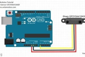
Step 1: Build the circuit

Materials:

1 * 42STH33-0404AC stepper motor
1 * SN754410NE ic chip
1 * power jack
1 * 12 VDC power supply

1 * breadboard

1 * Arduino

Jumper cables

Process:

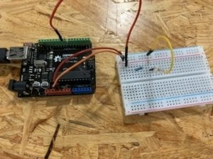
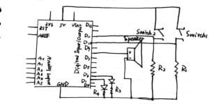
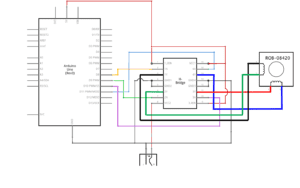
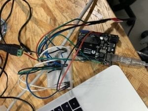
The schematic diagram is complicated at first sight and simply understanding the circuit cost several minutes. While connecting the components, I realized that the circuit was more symmetric and neater than I thought it will be, which makes the mistake quite obvious if the connection was wrong. After double-checking the connection of each jumper cables to avoid the  “potential damage to the computer,” I uploaded the code in the example and the stepper motor started to rotate regularly. To further test the circuit, I made some change to the number in the bracket of delay to adjust each of its rotating time. The stepper motor worked as I expected.

Step 2: Control rotation with a potentiometer

Materials:

1 * 42STH33-0404AC stepper motor
1 * SN754410NE ic chip
1 * power jack
1 * 12 VDC power supply
1 * breadboard

1 * Arduino

Jumper cables

1 * 10K potentiometer

Process:

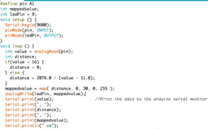
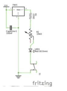
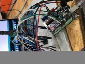
Though step 2 only required us to add a potentiometer into the circuit, I was confused about how to connect the three legs of the 10k potentiometer to their matching access port. Since the 10K potentiometer looked different with the potentiometer we used before. After seeking help from the assistant, I ultimately made it clear that the leg which is on the top of the potentiometer should be connected to the input port. And the other two legs respectively should connect power and the ground. Another problem I confronted with was how to edit the code so that the stepper motor can rotate as I rotate the potentiometer. At first, I defined some new variables to describe the value of the potentiometer and try to use the map function to link it with the stepper motor. But soon I realized that the variable was already described in the code and all I need to do was to add a map function. This time it also worked, yet there was some apparent delay time between rotating the potentiometer and the stepper motor changing its position.

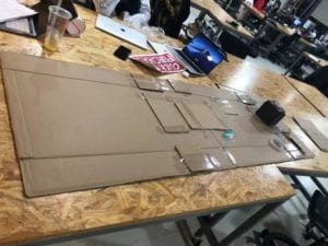
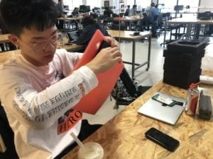
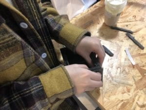
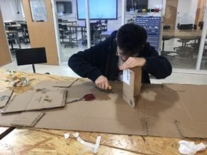
Step 3: Build a drawing machine

Materials:

2 * Laser-cut short arms

2 * Laser-cut long arms

1* Laser-cut motor holder

2 * 3D printed motor coupling

5 * Paper Fasteners

1 * Pen that fits the laser-cut mechanisms

Paper

Process:

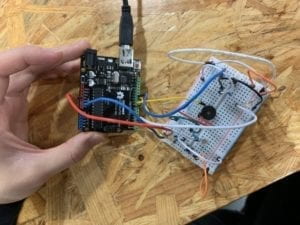
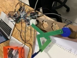
On the foundation of step 1 and 2, the third requirement seemed simple, yet the most interesting. We assembled two devices together with all the other components. During the process, the paper fasteners would drop from time to time and it was hard to fix the arms tightly together. The first time the distance between the pen and the paper was too far so we put some books under the paper to make them exactly just touch each other. Our operation afterward was smooth and though the final work was just like a doodle of a kid, it means a lot to us.

Question 1:

What kind of machines would you be interested in building? Add a reflection about the use of actuators, the digital manipulation of art, and the creative process to your blog post.

I will be interested in building a machine that can record and mimic the movement of the planets and the fixed stars in the universe to help the celestial observer observe the motion of the galaxy. To realize this program, sensors and observing machines can be installed in spaceports to record positions of stars at any time. The real-time data will be transferred back to the research centers on the ground. According to the data that reflects star’s positions, the stepper motors will change their position accordingly and planetary models installed on the stepper motors can also move their position to mimic the real-time movement of stars in the universe.

The theory is basically similar to the drawing machine. The observing machine serves as the potentiometers to change the information that computer receives, then the real-time data will be transmitted to the stepper motors which will act as the commands and instructions that the computer gives.

Question 2:

Choose an art installation mentioned in the reading ART + Science NOW, Stephen Wilson (Kinetics chapter). Post your thoughts about it and make a comparison with the work you did during this recitation. How do you think that the artist selected those specific actuators for his project?

Among all the programs mentioned in the reading, Virtual Brownies is a really interesting project which synthesizing the virtual world on the computer screen and the reality and catering to the nowadays sweeping trend of virtual reality. The feature of this project that changes, in reality, will also cause accordingly influence to the virtual world adds to the attractiveness and playability of this art installation. Comparing to our drawing machine, it leaves more space for users to explore, this can be more entertaining. It also shows a strong sense of interactivity as those small digital creatures will react to the changes in the reality following the regularity. To realizing this device, the artist may need a camera on the back of the device to observe the changes happening in the real life and then scan some specific objects onto the screen and then interact with the small digital creatures.

Recitation 4: Group Project by Yijia Chen(Kaycee)

How does advertisement look like in 2119?

Partners: Ellie, Mimi, Zhiqiu Wang

Before taking Inter-Lab, “Interaction” was a rather vague and abstract notion to me. Previously I thought interaction can happen between any two objects who have linguistic or any other form of communication. In the reading “The Art of Interactive Design”, the author identifies “interaction” as “a cyclic process in which two actors alternately listen, think and speak” and describes interactivity as a “continuous variable with relative measures”(The Art of Interactive Design, Crawford) which can be at different degree in different scenarios. This description gives me some hint of how I can improve my own cognition of interaction. Though interaction can happen in any two or more subjects, it shouldn’t be a mono-directional activity but requires reactions from both sides.  The metaphor which describes interaction as a linguistic communication between two actors in an act reveals that to truly interact with each other needs skills of both understanding and reacting, and the latter is on the premise of the former. In the reading “Making Interactive Art: Set the Stage, Then Shut Up and Listen”, the author further explains to truly let people experience an interactive project requires abandoning preconceived ideas and fully create a free explore environment.

The project Expressive Tactile Controls aligns with my definition of interaction. In this program, buttons with different personalities will act differently when reacting towards the moving of fingers. They will first understand if the outsider motion is approaching or going away and then show different reactions basing upon its previous understanding.

Another program called 90×200 doesn’t align with my definition of interaction. It is an installation that dramatizes the emotions of frustration, anxiety, and delirium through mechanical movements. Because it acts upon a set code from computer instruction thus doesn’t have the process of understanding and reacting.

After discussing our cognition of interaction, we ultimately decided to make the 4D interactive billboard as our group project because it best conveys our opinion towards interaction.

We mainly used cardboard and foamed plastic to make the main body of the billboard and the projector which will project digital salesman/saleswoman. In our design philosophy, the 4D interactive billboard shows interaction because it can recommend different goods for different people. It will first detect a person’s mood and then providing variable products that may cater to that person. Both the process of understanding and reacting are embodied clearly in this kind of interaction.

Recitation 3: Sensors-Young-by Yijia Chen(Kaycee)

Partner: Zhiqiu Wang

Circuit 1: Blink with an infrared distance sensor

Components:

1 * Arduino Uno

1 * infrared distance sensor

1 * LED

Jumper cables

Processes and problems we encounter:

We first connected the Arduino with the infrared distance sensor like the picture above.

This recitation was not like any previous recitations because we were not provided any visual aids of the circuit. But meanwhile, we could also explore something new and add our creativity into our work. We chose the infrared distance sensor and wanted to build a circuit in which the brightness of the LED can be adjusted to the distance the sensor sensed. However, at first, we could only let the LED on when the distance that sensor sensed was above some number and let it off when the distance was under some number.  We copied some language from examples tested it. At first, the serial monitor only showed two numbers which were not even close to the fact. We asked an assistant for help and found out that we mistakenly typed 0 as our input pin number but assemble the wire into port 2. We made some adjustment and tried again. This time, the circuit worked well.

Circuit 2: Fade with an infrared distance sensor

After our first success, we still wanted to try on the fading circuit. We used the mapping formula to transit the distance that the infrared distance sensor sensed into numbers between 0 to 255. We were confused at first about how to write the Arduino. After perusing and contemplating the programming, we found that there were only two lines we needed to copy from the example the website provided. Under the guidance of professors, we made the completed code, which was much cleaner and more simple than I thought it would be.

This is how the code looked like at last.

Question 1:

What did you intend to assemble in the recitation exercise? If your sensor/actuator combination were to be used for pragmatic purposes, who would use it, why would they use it, and how could it be used?

We intended to assemble a device in which the brightness of LED can adjust to the distance that the sensor sensed. I think it can be used as an energy-saving street lamp. The government can install such a device along the roads which are remote and far from the city center. Because there is usually few cars who will pass these streets, keeping all the street lamps there at full brightness can be a waste of energy. This device can save energy at a large degree. They can improve lighting levels when the infrared distance sensor detects cars coming and turn the brightness down when there are no moving things on the road.

Question 2:

Code is often compared to following a recipe or tutorial.  Why do you think that is?

When start coding, we need to first consider what variables we need in the following lines and present them at the very beginning. For example, in our second circuit, we defined pin as A1 and ledPin equals 9. Thus when we input pin or ledPin again afterward, the computer can recognize these “signals” and decide what we want it to do. This process is similar to making a recipe. The recipe maker will always present the food material this specific dish needs at the very first, then use these materials to produce something else.

Question 3:

In Language of New Media, Manovich describes the influence of computers on new media. In what ways do you believe the computer influences our human behaviors?

The computer serves as a medium in communication between human. Network drives social productivity to develop at a faster rate. There are increasing channels for people to understand and disseminate information. People can complete work and study tasks without leaving home, allowing everyone to save more time to deal with other things so that people are liberated in action and thought. However, almost every aspect of computers influence on human behavior has two sides. For example, in job marketing, computers replace workers of those hazardous work, but computers also converted them into unemployed people. Since the current network development has not yet reached a relatively perfect stage, the network still has a lot of virtuality and unreality, which leads to the development of the struggle in the ideological and political fields on the network.

Recitation 2. Arduino Basics by Yijia Chen

Partner: Zhiqiu Wang

Circuit 1: Fade

Components:

1 * Arduino Uno

1 * USB A to B cable

1 * breadboard

1 * LED

1 * 220-ohm resistor

Hook-up Wires

Process:

The process of building up the circuit went well since we had already done this practice in class. However, we still rely on the diagram provided at a great degree to help connect each component. During the process, we found two jumper cables that connect both sides of the breadboard and were not sure what they are for. To solve the puzzle, we asked another pair and got the answer that they served as the connection between two sides thus no matter which side the component was connecting, it was included in the circuit. In this circuit, these two jumper cables can be omitted because one side’s ports were enough for connecting.

Circuit 2: Tone Melody

Components:

1 * Arduino Uno

1 * USB A to B cable

1 * breadboard (optional)

1 * buzzer

Hook-up Wires

Process:

The process went smoothly because this circuit itself is a simple one. Even the breadboard can be omitted. Yet we still chose to include the breadboard into our circuit because it provided more stable connection and the hook-up wires and the buzzer were more easily to be connected.

Circuit 3: Speed Game

Components:

1 * Arduino Uno

1 * USB A to B cable

1 * breadboard

2 * LED

2 * 220-ohm resistor

Hook-up Wires

2 * 10K ohm resistors

2 * pushbuttons

1 * buzzer

Process:

Before building up the circuit, we met some problems with distinguishing resistors with different ohm. We tried to find a way to simply tell the differences without using multimeters. We had a vague memory about what the professor said before about the different color on the resistors but was not sure which color represented the resistors with lower ohm. Essentially, through some search, we found out that resistors that have two orange lines out of five while the 10k ohm resistor only have one.

We also met some difficulties while trying to place all the components in the right position and also connect them properly. It took us several minutes to figure out how the current flowed in the circuit. Also when connecting jumper cables, we lost several times when placing wires into ports. Finally, we successfully built the circuit and played two times with the device.

Question 1

Reflect how you use technology in your daily life and on the circuits you just built. Use the text Physical Computing and your own observations to define the interaction.

It seems impossible nowadays to live without technology. The technology that most familiar to me is my communication tool——my phone, as well as computers since I use it to help me record notes from classes and finish homework. Before taking IMA classes, I only enjoy the benefit from technology development but haven’t truly engaged in creating any technological device. While building the circuits, my partner and I also relied on the guidance and diagram, which are also the accomplishment of others, to a great degree. However, it’s a different approach from just using technology. In my opinion, there are three ways to approach technology, using it, combining and understanding it, and creating it. In the process of building the circuits, we moved on to the second level of approaching technology and utilize the principles to engage in the technology rendered us first-hand experience upon exploring this area.

According to Physical Computing, interaction is “an iterative process of listening, thinking, and speaking between two or more actors” (“facts”). When putting in the context of physical computing, the three stages——listening, thinking, and computing of interaction are just like input processing and output of computers. In my opinion, computers serve as tools for people to interact with each other rather than being an object itself. Computers enable interaction to take place without the limitations of time and distance.

Question 2

If you have 100,000 LEDs of any brightness and color at your disposal, what would you make and where would you put it?

I would install them in the theater. Each part of these LEDs are connected to a specific pitch and when Musicals are playing, the corresponding LEDs will light up and their color can change according to the music, to give the audience a better experience.

Week1: Recitation Documentation-Kaycee(Yijia Chen)

Partner: Zhiqiu Wang

Instructor: Young

Circuit1 Door Bell

Components and their functions:

Push button: connect/disconnect the circuit to let the electric current pass/not pass to control the on/off of the speaker

12V power:  provide power for the whole circuit

Speaker: make sound

Capacitor: store electricity, let the electric current change slowly to protect the circuit

Wire: connect different components of the circuit

Voltage regulator: regulate voltage

Breadboard: fix all components and provide connections between them

The process of building the circuit:

At first, we’re confused because it was the first time for both me and my partner to use a breadboard. Therefore, we have to ask for help to figure out how this component worked. Things got more smoothly after we got familiar with the inner structure of the breadboard. We built the circuit and adjusted some of the wire under the guidance of professors, but to our disappointment, when we pushed the push button, the speaker didn’t make any sound. We together with professors tried to find the problem by testing each component of the circuit but failed to figure it out. Therefore, we picked another set of all components and test our circuit again. This time it worked.

Circuit 2: Lamp

Components and their functions:

12V power:  provide power for the whole circuit

Voltage regulator: keep the voltage at a stable number

Capacitor: store electricity, let the electric current change slowly to protect the circuit

Wire: connect different components of the circuit

Breadboard: fix all components and provide connections between them

Push button: connect/disconnect the circuit to let the electric current pass/not pass to control the on/off of the LED

LED: shine

220-ohm resistor: ensure the current is running within a safe range

The process of building the circuit:

Since the first circuit has provided us with some basic knowledge of how the breadboard works, we connected the whole circuit quickly and adjusted fewer than before since fewer mistakes took place. However, when we pushed the button, the LED didn’t light up as we expected. We still seek help from instructors but again, he couldn’t tell where was the problem thus we had to change another set again. Luckily, the LED light up in our second try.

Circuit 3: Dimmable Lamp

Components and their functions:

12V power:  provide power for the whole circuit

Voltage regulator: keep the voltage at a stable number

Capacitor: store electricity, let the electric current change slowly to protect the circuit

Wire: connect different components of the circuit

Breadboard: fix all components and provide connections between them

Push button: connect/disconnect the circuit to let the electric current pass/not pass to control the on/off of the LED

LED: shine

Variable resistor: change the resistance to change the amount of current

The process of building the circuit:

This time the process went quite well since we used the same set in circuit 2 so every component can be guaranteed working normally. And we only added a variable resistor. The brightness of LED can be witnessed changed obviously when we rotating the variable resistor.

Question 1:

After reading The Art of Interactive Design, in what way do you think that the circuits you built today include interactivity? Please explain your answer.

According to my understanding of The Art of Interactive Design, interactivity is two or more agents respond to each other’s action. This process includes first understanding the other’s action and then react to it and then flipping the order to form a loop. In our practice, I think the stitch shows this kind of interactivity because when people push the button, the circuit is closed and current flows to make the speaker or the LED works. It understands and responds to people’s action of pushing the button.

Question 2:

How can Interaction Design and Physical Computing be used to create Interactive Art? You can reference Zack Lieberman’s video or any other artist that you know.

Because interactive art is an activity relates more than one single agent. Therefore, the more controllable parts in the circuit, the more degree of interactivity it shows with people. We can build more components which can be adjusted or controlled by people into the circuit or any other physical computing program to increase the interactivity.