Week 3 Assignment Sharon

What are the main challenges in applying mainstream mobile technologies to meet the needs of people who have autism or other cognitive disabilities?

1. For people with cognitive disabilities, learning new functions on mobile devices can be difficult. The mobile technologies may not be that accessible to them.
2. The problems of people with cognitive disabilities are very diverse and there are many special cases. Therefore, the design of products is often customized according to different special needs, which may lead to a lack of capital. Few companies are willing to spend a lot of capital to produce products with low profits.
3. Today’s technology is not fully developed, and some requirements cannot be met due to technical constraints.

List three benefits of making mainstream mobile technologies accessible for people with autism or other cognitive disabilities.

1. Mobile technologies can offer different ways that canā€™t be achieved by the traditional methods to help people with cognitive disabilities learn about the world comprehensively. According to Chapter 15, notebook computers, mobile phones, and tablets have been programmed to function as both augmentative communication devices (see Chapter 16) and as cognitive assists (Stock et al, 2008). They have an output of either speech or visual characters and text. These input/ output features may be operated in many different ways.
2. Mobile technologies can help strengthen memory. As is talked in the text, reminding people to take their medication is one of the main uses of memory assistance technologies.
3. Mobile technologies can help people with cognitive disabilities have a sense of time. In the text, we know there is one class of devices that uses an alternative format for representing time to make it more accessible to individuals with intellectual disabilities.

How can technologies help to overcome stigma and discrimination for people with autism or other cognitive disabilities?

1. Cognitive disabilities are often regarded as a part of the social identity of people who have them. When the person with such social identity utilizes assistive technologies, especially those based on mainstream technologies, ā€œthere is a perception of competence and skill resulting from device use that can positively impact social interaction and self-imageā€ (404).
2. When using online devices, people with cognitive disabilities can have the opportunity to choose whether or not to disclose their disability. So they can communicate with others without disclosing the disability.
3. Technologies designed for people with cognitive disabilities can let them regain the ability to access the Internet. Because of their disabilities, they often cannot access the Internet as others, but mobile devices designed for them can allow them to regain access to the Internet, as long as designers pay attention to some aspects of the deviceā€™s design.

A Unique Mask-changing Performance – Sharon Xu – Professor Rudi

CONCEPTION AND DESIGN:

In the group research paper, according to Crawfordā€™s article The Art of Interactive Design, I defined interaction as a cyclic process where two actors take turns to receive and respond to the message, which in computer terms are called: input, processing, and output. But as the learning progresses, my definition of interaction becomes richer and more detailed. in the final research paper, I studied a project called Anti-Drawing Machine. 

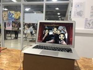
Through usersā€™ feedback in the video, we can see that users enjoy the project. Also, after discussing with professors and some classmates, I find this project can reflect human’s feeling of being not able to control machines and then trigger people’s thinking about the relationship between people and machines. Therefore, I think this project is not only interesting but also meaningful. So I have two new understandings of interaction: 1. The product should make the user feel motivated to proceed to the next round of input; 2. The product should be interesting and make users think or learn something or expose to a new experience. So I begin to think about creating something both interesting and meaningful. Meanwhile, I happened to see the mask-changing performance online and itā€™s reported that many people, especially teenagers, are not valuing or even forgetting the Chinese traditional mask-changing art. I think itā€™s mainly because of the lack of promotion of media. So I decided to make a project to promote this kind of art and catch peopleā€™s attention to it. First, in order to track users’ face, I used the OpenCV library in Processing to achieve the purpose of face recognition and tracking. Then I found some famous existing masks in the mask-changing performance on the Internet and used the image processing software to adjust its size and background to match the user’s face. Instead of choosing a bottom, Iā€™d like to use a distance sensor to make the user’s body (or hands) move as much as possible. Also, I planned to provide background music and the costume to create an atmosphere of the performance.

FABRICATION AND PRODUCTION:

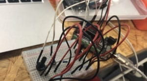
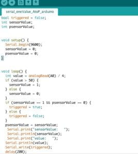
My first step was to program the mask stickers to the user’s face. I successfully implemented this function by using the knowledge about image and media I learned in class. I then installed the distance sensor to transfer the information from Arduino to processing. Here I encountered a difficulty: when the distance detected by the sensor is less than a specific value, processing receives the data and makes the mask keep changing. In other words, I failed to make it change the mask just once with a change of distance. I tried a lot of logic, like if(), while(), and so on, but it didn’t work. Finally, I came up with an idea of using a Boolean function. With the help of Nick, I successfully wrote the code on Arduino to realize the function of changing the mask once with one change of distance.
After implementing the basic functionality, I adjusted the position of the distance sensor to make it more sensitive to the movement of the user. Also, following the advice of professor Rudi, I added the frame of a stage curtain at the edge of the computer screen to make it have more atmosphere of stage performance. After the first round of user test, I got a lot of valuable opinions and had the following modification plan:

  1. Change the way sensor function
  2. Flip the video mirror-move in the same direction as the user
  3. Optimize the speed of camera video
  4. Let the curtain cover the video to create the feeling on stage
  5. Add the sound of a fan
  6. Make screenshot (use saveFrame() function)
  7. Attach Arduino to the fan

I want to first focus on the choice of the sensor. During the user test, many users told me that they couldn’t understand the meaning of moving their hands closer to the computer screen (to trigger the distance sensor), which made me rethink how to design the sensor to make users feel natural to move. So I thought that I could attach an acceleration sensor to a fan to change the way the sensor function. Then I tested it.

The accelerometer worked well. So I attached it on the fan. Here I had a problem: because the accelerometer measured three-dimensional space and the user’s gestures were so diverse that it is difficult to predict their movement, the sensor on the fan was not as sensitive as I measured before. After careful consideration, I chose a fan with a distance sensor as my Arduino part. Later, I invited some friends to experience it as users. The feedback they gave me was that the sensor system gave users a sense of performance while being sensitive. So I chose the distance sensor. In addition, another big problem I encountered in the production process is that the camera’s image display is not smooth. For this reason, I have optimized and checked my Processing code several times. With the help of Rudi and Tristan, I corrected the order of importing pictures, deleted some unnecessary delay () functions, and removed the “resize()” process of background pictures. In this way, my project ran much smoother than before. Also, I optimized the above seven items and made my project better. I think the user test is very helpful for my project because it lets me know the real experience and thoughts of users and gives me ideas to improve the project.

CODE FOR PROCESSING

ļ¼ˆAttached belowļ¼‰

CONCLUSIONS:

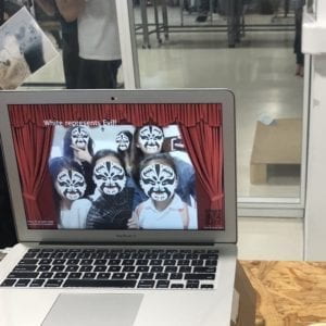
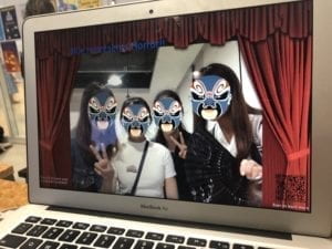
The main purpose of my project is to let people experience the fun of mask-changing performance. This traditional Chinese Art can only be given by performers with professional skills. But with this project, everyone could have the chance to give a unique mask-changing performance. Whatā€™s more, I provided the background knowledge (different colorsā€™ meanings in masks) to let users know more about mask-changing. By providing the QR code, this project gives people with interest in learning more direct access to the information about mask-changing performance. This project meets my definition of interaction. The first one is that “the product should make the user feel motivated to proceed to the next round of input”. During the IMA show, I felt my users, especially kids and teenagers, were very excited about my project. And some kids could play it for more than 5 minutes. Users were attracted by different kinds of masks and their faces on the screen. Many users would like to make a screenshot or use their phones to take photos. So I felt my project was interesting and attractive to users.  For the second one, “the product should be interesting and make users think or learn something or expose to a new experience”. During the IMA show, many users came to me, asked me about mask-changing performance and scanned the QR code to learn more. Also, when interacting with the computer, many mothers would ask their kids about the meanings of different masks’ color, which were shown on the screen. So I think my project could arouse people’s attention to traditional mask-changing performance and somehow play a propaganda role for it. In short, my project met my expectations. In the future, I will try to develop this project, such as perfecting screenshot function, adding video recording function and seizing the opportunity to find more users’ test and feedback.
CODE FOR PROCESSING

import gab.opencv.*;
import processing.video.*;
import java.awt.*;
import processing.serial.*;
import processing.sound.*;
SoundFile file;

PImage a;
Serial myPort;
int sensorValue;
String w;

Capture video;
OpenCV opencv;

// List of my Face objects (persistent)
ArrayList<Face> faceList;

// List of detected faces (every frame)
Rectangle[] faces;

// Number of faces detected over all time. Used to set IDs.
int faceCount = 0;

// Scaling down the video
int scl = 2;
PImage[] myImageArray;
PImage bgphoto;
PImage QR;

//PImage img2; if….
int i1;
int sizeX = 896; //this has to be a multiple of ???? 640/480
int sizeY = 672;
int offsetX = -120;
int offsetY = 50;

void setup() {

fullScreen(); //size(800, 600);
video = new Capture(this, sizeX/scl, sizeY/scl);
opencv = new OpenCV(this, sizeX/scl, sizeY/scl);
opencv.loadCascade(OpenCV.CASCADE_FRONTALFACE);

faceList = new ArrayList<Face>();
video.start();
printArray(Serial.list());
// this prints out the list of all available serial ports on your computer.

myPort = new Serial(this, Serial.list()[ 16 ], 9600);
myImageArray= new PImage[15];
for (int it =0; it< myImageArray.length; it++) {
myImageArray[it]=loadImage(it + “.png”);
}
//img2 = loadImage(“balabala.jpeg”);
bgphoto=loadImage(“12345.png”);
bgphoto.resize(width, height);
QR=loadImage(“QR1.png”);
}

void draw() {
background(96, 0, 7);
while ( myPort.available() > 0) {
sensorValue = myPort.read();
}
//println(sensorValue);

//scale(scl);
opencv.loadImage(video);
pushMatrix();
scale(scl);
translate(video.width, 0);
scale(-1,1);
image(video, offsetX, offsetY );
// pushMatrix();
// translate(100, 100);//(width – sizeX, height -sizeY);
detectFaces();
// Draw all the faces
for (int i = 0; i < faces.length; i++) {
noFill();
strokeWeight(5);
stroke(255, 0, 0);
//rect(faces[i].x*scl,faces[i].y*scl,faces[i].width*scl,faces[i].height*scl);
//rect(faces[i].x, faces[i].y, faces[i].width, faces[i].height);

if (sensorValue== 1) {
file = new SoundFile(this, “fan.wav”);
file.play();
i1=int(random(0, 15));
}

image(myImageArray[i1], faces[i].x+offsetX, faces[i].y+offsetY, faces[i].width, faces[i].height);
//delay(10);
}
//popMatrix();
//for (Face f : faceList) {
// strokeWeight(2);
// //f.display();
//}
//scale(scl);
popMatrix();

image(bgphoto, 0, 0);

if (i1==0) {
w=”Yellow represents Bravery!!”;
textSize(48);
fill(252, 233, 3);
text(w, 230, 140);

}
if (i1==1) {
w=”Blue represents Horror!!OMG!”;
textSize(48);
fill(0, 0, 255);
text(w, 230, 140);
}
if (i1==2) {
w=”White represents Evil!”;
textSize(48);
fill(255, 255, 255);
text(w, 230, 140);
}
if (i1==3) {
w=”Red represents Loyalty!”;
textSize(48);
fill(255, 0, 0);
text(w, 230, 140);
}
if (i1==4) {
w=”White represents Evil!”;
textSize(48);
fill(255, 255, 255);
text(w, 230, 140);
}
if (i1==5) {
w=”Red represents Loyalty!”;
textSize(48);
fill(255, 0, 0);
text(w, 230, 140);
}
if (i1==6) {
w=”White represents Evil!”;
textSize(48);
fill(255, 255, 255);
text(w, 230, 140);
}
if (i1==7) {
w=”Red represents Loyalty!”;
textSize(48);
fill(255, 0, 0);
text(w, 230, 140);
}
if (i1==8) {
w=”Green represents Horror!!”;
textSize(48);
fill(0, 255, 0);
text(w, 230, 140);
}
if (i1==9) {
w=”White represents Evil!”;
textSize(48);
fill(255, 255, 255);
text(w, 230, 140);
}
if (i1==10) {
w=”Red represents Loyalty!”;
textSize(48);
fill(255, 0, 0);
text(w, 230, 140);
}
if (i1==11) {
w=”Green represents Horror!!”;
textSize(48);
fill(0, 255, 0);
text(w, 230, 140);
}
if (i1==12) {
w=”Blue represents Horror!!OMG!”;
textSize(48);
fill(0, 0, 255);
text(w, 230, 140);
}
if (i1==13) {
w=”Blue represents Horror!!”;
textSize(48);
fill(0, 0, 255);
text(w, 230, 140);
}
if (i1==14) {
w=”Yellow represents Bravery!!”;
textSize(48);
fill(252, 233, 3);
text(w, 230, 140);
}
textSize(20);
fill(255, 255, 255);
text(“Press R to save your”, 0, 730);
text(“wonderful moment!”, 0, 750);
textSize(15);
text(“Scan to learn more”, 1200, 740);
//imageMode(CENTER);
image(QR, 1200, 600);
// popMatrix();
}

void keyPressed() {
println(key);
if (key == ‘r’ || key == ‘R’) {
saveFrame();
}
}
void detectFaces() {

// Faces detected in this frame
faces = opencv.detect();

// Check if the detected faces already exist are new or some has disappeared.

// SCENARIO 1
// faceList is empty
if (faceList.isEmpty()) {
// Just make a Face object for every face Rectangle
for (int i = 0; i < faces.length; i++) {
println(“+++ New face detected with ID: ” + faceCount);
faceList.add(new Face(faceCount, faces[i].x, faces[i].y, faces[i].width, faces[i].height));
faceCount++;
}

// SCENARIO 2
// We have fewer Face objects than face Rectangles found from OPENCV
} else if (faceList.size() <= faces.length) {
boolean[] used = new boolean[faces.length];
// Match existing Face objects with a Rectangle
for (Face f : faceList) {
// Find faces[index] that is closest to face f
// set used[index] to true so that it can’t be used twice
float record = 50000;
int index = -1;
for (int i = 0; i < faces.length; i++) {
float d = dist(faces[i].x, faces[i].y, f.r.x, f.r.y);
if (d < record && !used[i]) {
record = d;
index = i;
}
}
// Update Face object location
used[index] = true;
f.update(faces[index]);
}
// Add any unused faces
for (int i = 0; i < faces.length; i++) {
if (!used[i]) {
println(“+++ New face detected with ID: ” + faceCount);
faceList.add(new Face(faceCount, faces[i].x, faces[i].y, faces[i].width, faces[i].height));
faceCount++;
}
}

// SCENARIO 3
// We have more Face objects than face Rectangles found
} else {
// All Face objects start out as available
for (Face f : faceList) {
f.available = true;
}
// Match Rectangle with a Face object
for (int i = 0; i < faces.length; i++) {
// Find face object closest to faces[i] Rectangle
// set available to false
float record = 50000;
int index = -1;
for (int j = 0; j < faceList.size(); j++) {
Face f = faceList.get(j);
float d = dist(faces[i].x, faces[i].y, f.r.x, f.r.y);
if (d < record && f.available) {
record = d;
index = j;
}
}
// Update Face object location
Face f = faceList.get(index);
f.available = false;
f.update(faces[i]);
}
// Start to kill any left over Face objects
for (Face f : faceList) {
if (f.available) {
f.countDown();
if (f.dead()) {
f.delete = true;
}
}
}
}

// Delete any that should be deleted
for (int i = faceList.size()-1; i >= 0; i–) {
Face f = faceList.get(i);
if (f.delete) {
faceList.remove(i);
}
}
}

void captureEvent(Capture c) {
c.read();
}

Reflection on Rube Goldberg Machine by Sharon Xu

Group Members (Group 5): Molly, Quilla, Sharon

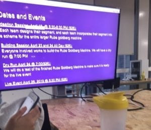
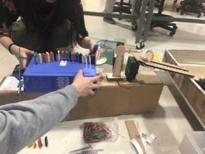
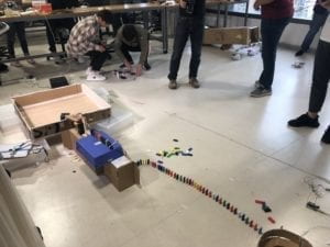
From April 9 to April 26, I joined the Rube Goldberg Machine Program. The whole process is separated by five sessions: Info Session(4/9), Ideation Session(4/19), Building Session (4/23&4/24), Dry Run (4/25&4/26), Live Event (4/26).

Info Session(4/9)

On April 9 I attended the Info Session about Rube Goldberg Machine. In this session, I learned what Rube Goldberg Machine is and how the program would be. After the class, I made a group with Molly and spent one hour and a half to brainstorm our part for the Machine with Molly. Molly and I came up with many ideas through this brainstorm, which laid the foundation for our follow-up team’s operation route.

After the Info Session, I invited Quilla, who took Interaction Lab last semester, to join us to build the Goldberg Machine. On April 14, we gathered together and integrated our ideas. Finally, we determined our complete route, which will be explained later.

On April 15, we began to build the route. Before we started, we shared our idea with Nick. Nick suggested we simply our long route and try to make it practical and easier to realize. Therefore, after careful consideration, we decided to remove the Chinese shadow play and laser parts, which are hard to achieve and not so meaningful for our route. We then began our work.

Ideation Session(4/19)

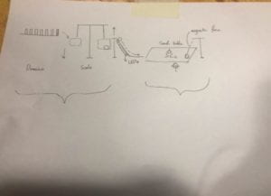
In the Ideation Session, we met the other groups and shared our idea with professors and other students. Since our group’s idea had been formed before the session, after listening to the suggestions from the two professors in the ideation session, we made some small changes to our route, such as considering the connection between the two ends of the balance. After the Ideation Session, I summarized our ideas, documented them and submitted it to Leo. The doc is as follows:

We plan to use the dominoes and attach extra weight to the last domino and let it fall on one side of the scale. On the other side of the scale, there will be a magnet ball. After the last domino falls, the side of the scale with the ball will rise and hit the top of the track, and the ball will move on to the track. There will be LEDs along the track that turns on when the ball gradually passes by. The ball then falls into a specific spot of the sand table, starting to draw a simple pattern representing Shanghai (assumably the Oriental Pearl TV Tower). The mechanism of the drawing process is that the magnetic ball is attracted and driven by a robot underneath that draws the pattern. How the robot is triggered may be that it has sensed the pressure of the ball or the magnetic force from the ball. When the ball has finished drawing, it goes to a specific spot that has a magnet on top. It would be attracted to the magnet and trigger the next group.

MATERIALļ¼š

Dominoes

A scale

A magnet ball

LEDs

Track

Sand Table

Robotic car

Pressure sensor/Electromagnetic force sensor

Magnet

Building Session (4/23&4/24)

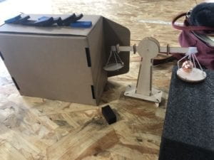
During the week of 4/23, we worked on the Goldberg Machine. I was in charge of the part from Domino to Bridge. I prepared the domino and the scale in advance. Quilla and I first worked on the bridge part. For the decoration, we used conductive tape, button batteries, and LEDs to make LEDs light up when the ball passes by.

After building the bridge, I worked on the scale and domino to make it be a smooth route using boxes and sponge blocks. And it worked on the table!

Dry Run (4/25&4/26)

Here I met the biggest problem: Since my part needs a certain height to operate, while the part of our previous group is output on the ground, connecting the two parts has become a big problem. After much thought, struggle, and modification, finally we decided to use a stick to trigger the domino. We made a stick using screws and components. But it was hard to make the stick work. In the first day of the test, we sometimes succeeded and sometimes failed (failure accounts for the majority).

On the following day, in order to improve the success rate, I kept experimenting and finally found the secret to make it successful: make the top end of the stick close to the domino, and make the bottom end keep a certain distance from the domino. With this trick, our success rate has improved greatly, to almost ninety percent. I was so excited about what we had achieved and also a little worried about whether we could still succeed in the live event.

Live Event (4/26)

Excited! Our group’s work successfully operated!

After this project, I felt a sense of achievement through my own efforts to build the Goldberg Machine and the collective sense of cooperation with all the groups. Although I met with difficulties during the period, I finally overcame it and successfully achieved the expected goal. Due to the urgency of time, there are still some things we can do better in the project, such as the functions of LEDs are not well realized. We’ll pay more attention to time arrangement next time.

Reflection on Processing Workshop by Sharon Xu

On April 11, I attended the Processing Workshop held by Leon. In this workshop, we reviewed the functions in Processing we learned before and practiced them to make animation. We first reviewed some 2D primitives fictions such as ellipse(), rect() and so on. Leon also clearly introduced how to use rectMode() and ellipseMode() to adjust the position of the base point of the graph rotation. We used the following exercise to apply the functions we learned to make a red circle move.

Video of My Work 1

Code

int sizeOfBall=200;

void setup(){//This happens once

  size (1000,800);

  background(255,100,0);//background (0-255),background(r,g,b)

  frameRate(15);//By default, the frameRate is 60 fps…

  rectMode(CENTER);

}

void draw(){

  println(frameCount);

  background(255);

  fill(255,0,0);//fill (r,g,b)

  ellipse(width/2,frameCount, sizeOfBall, sizeOfBall);//a ball should exist…

  //strokeWeight(5);

  //stroke(0,255,0);

  noStroke();

  //the ball should go down…

  //the ball should bounce back up when it hits the edge…

}


Then we learned how to change the color of a pattern, how to determine the rotation vertex of the pattern, how to make the pattern move with the mouse. Through Leon’s detailed explanation, I understand the meaning of each function. For example,  I asked Leon what the frameRate function is. And then I learned that the frameRate is the frequency at which a continuous image is displayed. This workshop helped me solve my question about pushMatrix() and popMatrix(). I learned these two functions is just like the bracket to make a certain code only happen between push&pop.

Also, I learn the new functions vertex() and endShape(). With these two functions, I was able to draw patterns arbitrarily through Processing, which facilitated my ability to draw with Processing. This workshop is helpful for me as a beginner of Processing.

Video of My Work 2

Code

int sizeOfBall=200;

float r,g,b;

void setup(){//This happens once

  size (1000,800);

  background(255,100,0);//background (0-255),background(r,g,b)

  frameRate(15);//By default, the frameRate is 60 fps…

// rectMode(CENTER);

}

void draw(){

  println(frameCount);

  background(255);

// r= random (255);// random( lowerValue, upperValue)

// g= random (255);

// b= random (255);

  //fill(r,g,b,150);//fill (r,g,b,alpha)

  colorMode(HSB);//h/s/b

  //ellipse(mouseX,mouseY, sizeOfBall, sizeOfBall);//a ball should exist…

  //strokeWeight(5);

  //stroke(0,255,0);

  noStroke();

  //the ball should go down…

  //the ball should bounce back up when it hits the edge…


  //beginShape();

  //vertex (10,45);

  //vertex(50,200);

  //vertex(20,600);

  //vertex(700,50);

  //endShape(CLOSE);


  pushMatrix();

  translate(width/2,height/2);//imagine a new screen vertex start from middle//my 0,0 position is width/2,height/2

  rotate(radians(45));

  rect(0,0,sizeOfBall,sizeOfBall);

  popMatrix();//only happen between push&pop


  fill(frameCount,255,255);

  rect(mouseX, mouseY, 100,100);

   //beginShape();

// vertex (mouseX+100, mouseY-50);

// vertex(mouseX-500,mouseY+60);

// vertex(mouseX+300,mouseY-54);

  //endShape(CLOSE);

  ellipse(0,0, sizeOfBall, sizeOfBall);


}

Recitation 11: Workshops by Sharon Xu

Reflection

In this recitation, I attended the serial communications workshop held by Young. In this workshop, I consolidated the knowledge about how to send multiple values both from Arduino to Processing and Processing to Arduino. At the beginning of the class, all the students talked about the sensors they were going to use for their final project and the sending direction of values. Mine is a distance sensor sending values from Arduino to Processing. First, in order to practice, we used two potentiometers and one push button to send values from Arduino to Processing. The potentiometers sent analog values and the push button sent digital values. According to young’s instructions, I did it successfully.

Then we switch to practice sending values from Processing to Arduino. By moving the mouse, the user can adjust the brightness of the LED. At first, I failed to run the code because I forgot to change the numbers of value, but later I realized and run the code successfully. In the process, I learned how to write the code I need based on the sample code and better understood the meaning of the code. I could use the same logic to write the code for my final project.

Video of my work

Code

ARDUINO

// IMA NYU Shanghai

// Interaction Lab

/**

  This example is to send multiple values from Processing to Arduino.

  You can find the Processing example file in the same folder which works with this Arduino file.

  Please note that the echo case (when char c is ‘e’ in the getSerialData function below)

  checks if Arduino is receiving the correct bytes from the Processing sketch

  by sending the values array back to the Processing sketch.

**/

#define NUM_OF_VALUES 2    /** YOU MUST CHANGE THIS ACCORDING TO YOUR PROJECT **/

/** DO NOT REMOVE THESE **/

int tempValue = 0;

int valueIndex = 0;

/* This is the array of values storing the data from Processing. */

int values[NUM_OF_VALUES];

void setup() {

  Serial.begin(9600);

  pinMode(9,OUTPUT);

  pinMode(11,OUTPUT);

}

void loop() {

  getSerialData();

  // add your code here

  // use elements in the values array

  // values[0]

  // values[1]

int brightness1=map(values[0],0,500,0,255);

int brightness2=map(values[0],0,500,0,255);

analogWrite(9, values[0]);

analogWrite(11, values[1]);

}

//recieve serial data from Processing

void getSerialData() {

  if (Serial.available()) {

    char c = Serial.read();

    //switch – case checks the value of the variable in the switch function

    //in this case, the char c, then runs one of the cases that fit the value of the variable

    //for more information, visit the reference page: https://www.arduino.cc/en/Reference/SwitchCase

    switch (c) {

      //if the char c from Processing is a number between 0 and 9

      case ‘0’…’9′:

        //save the value of char c to tempValue

        //but simultaneously rearrange the existing values saved in tempValue

        //for the digits received through char c to remain coherent

        //if this does not make sense and would like to know more, send an email to me!

        tempValue = tempValue * 10 + c – ‘0’;

        break;

      //if the char c from Processing is a comma

      //indicating that the following values of char c is for the next element in the values array

      case ‘,’:

        values[valueIndex] = tempValue;

        //reset tempValue value

        tempValue = 0;

        //increment valuesIndex by 1

        valueIndex++;

        break;

      //if the char c from Processing is character ‘n’

      //which signals that it is the end of data

      case ‘n’:

        //save the tempValue

        //this will b the last element in the values array

        values[valueIndex] = tempValue;

        //reset tempValue and valueIndex values

        //to clear out the values array for the next round of readings from Processing

        tempValue = 0;

        valueIndex = 0;

        break;

      //if the char c from Processing is character ‘e’

      //it is signalling for the Arduino to send Processing the elements saved in the values array

      //this case is triggered and processed by the echoSerialData function in the Processing sketch

      case ‘e’: // to echo

        for (int i = 0; i < NUM_OF_VALUES; i++) {

          Serial.print(values[i]);

          if (i < NUM_OF_VALUES – 1) {

            Serial.print(‘,’);

          }

          else {

            Serial.println();

          }

        }

        break;

    }

  }

}

PROCESSING

// IMA NYU Shanghai

// Interaction Lab

/**

* This example is to send multiple values from Processing to Arduino.

* You can find the arduino example file in the same folder which works with this Processing file.

* Please note that the echoSerialData function asks Arduino to send the data saved in the values array

* to check if it is receiving the correct bytes.

**/

import processing.serial.*;

int NUM_OF_VALUES = 2;  /** YOU MUST CHANGE THIS ACCORDING TO YOUR PROJECT **/

Serial myPort;

String myString;

// This is the array of values you might want to send to Arduino.

int values[] = new int[NUM_OF_VALUES];

void setup() {

  size(500, 500);

  background(0);

  printArray(Serial.list());

  myPort = new Serial(this, Serial.list()[28], 9600);

  // check the list of the ports,

  // find the port “/dev/cu.usbmodem—-” or “/dev/tty.usbmodem—-”

  // and replace PORT_INDEX above with the index of the port

  myPort.clear();

  // Throw out the first reading,

  // in case we started reading in the middle of a string from the sender.

  myString = myPort.readStringUntil( 10 );  // 10 = ‘\n’  Linefeed in ASCII

  myString = null;

}

void draw() {

  background(0);

  // changes the values

  for (int i=0; i<values.length; i++) {

    values[i] = i;  /** Feel free to change this!! **/

  }

  values[0]=mouseX;


  values[1]=mouseY;

  // sends the values to Arduino.

  sendSerialData();

  // This causess the communication to become slow and unstable.

  // You might want to comment this out when everything is ready.

  // The parameter 200 is the frequency of echoing.

  // The higher this number, the slower the program will be

  // but the higher this number, the more stable it will be.

  echoSerialData(200);

}

void sendSerialData() {

  String data = “”;

  for (int i=0; i<values.length; i++) {

    data += values[i];

    //if i is less than the index number of the last element in the values array

    if (i < values.length-1) {

      data += “,”; // add splitter character “,” between each values element

    }

    //if it is the last element in the values array

    else {

      data += “n”; // add the end of data character “n”

    }

  }

  //write to Arduino

  myPort.write(data);

}

void echoSerialData(int frequency) {

  //write character ‘e’ at the given frequency

  //to request Arduino to send back the values array

  if (frameCount % frequency == 0) myPort.write(‘e’);

  String incomingBytes = “”;

  while (myPort.available() > 0) {

    //add on all the characters received from the Arduino to the incomingBytes string

    incomingBytes += char(myPort.read());

  }

  //print what Arduino sent back to Processing

  print( incomingBytes );

}