Materials
Breadboard
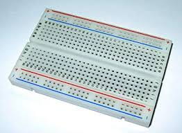 A device that helps organize one’s mind when one is new to building circuits. Electronic components can be easily interconnected by inserting their ‘legs’ into the holes of a breadboard. The holes are connected with each other by certain rules like there are wires embedded under.
https://www.amazon.com/BB400-Solderless-Plug-BreadBoard-tie-points/dp/B0040Z1ERO
LM7805 Voltage Regulator
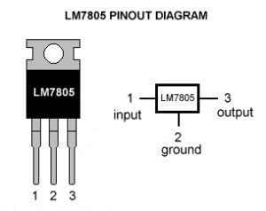 This is used to obtain an output voltage that is friendly to the buzzer and LED we use.
https://electronicsforu.com/resources/learn-electronics/7805-ic-voltage-regulator
Buzzer
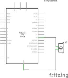
 This serves as the output of the first circuit we build. When applied with a sufficient amount of current, it gives a noise indicating that the circuit is working.
https://wp.nyu.edu/shanghai-ima-interaction-lab/category/recitations/
Push-Button (Switch)
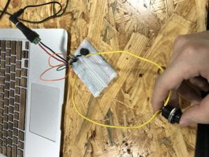 When pushed, allows current to run through and makes the entire circuit function. But my partner and I used our own button to do the trick. We soldered this button.
Arcade Button
Another kind of switch. We didn’t use it though.
220-ohm Resistor
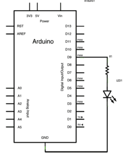
This is used to add resistance into the entire circuit so that the voltage will not all be applied onto the speaker or the LED, preventing them from being burned.
LED
This serves as the output in our circuit. It is very cheap but easy to burn. Therefore, we must very carefully choose the right resistor to take the heat off its back. It has a longer leg and a shorter leg. The current should run into the LED from the longer leg and leave the LED through the shorter leg.
100 nF (0.1uF) Capacitor
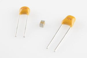 I am not entirely sure what it does in our circuit, but I know that it has something to do with storing electrical energy.
https://wp.nyu.edu/shanghai-ima-interaction-lab/category/recitations/
10K ohm Variable Resistor (Potentiometer)
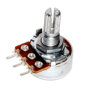 This is a resistor whose resistance we can control. In the third circuit, it serves as a way to control the brightness of the LED.
https://wp.nyu.edu/shanghai-ima-interaction-lab/category/recitations/
12-volt power supply
It serves as an adaptor that turns 220V AC to 12V DC, which is a friendly voltage for our circuits.
Barrel Jack
It serves as the bridge that connects the power supply to the breadboard.
Multimeter
We used it to measure the resistance of all the resistors we got from the box and find the right resistor of 220-ohm.
Several Jumper Cables (Hook-up Wires)
These are breadboard-friendly. Very easy to use.
Circuits
Circuit 1: Door Bell
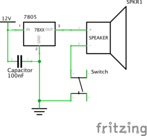
https://wp.nyu.edu/shanghai-ima-interaction-lab/category/recitations/
Above is the video of it working.
Circuit 2: Lamp
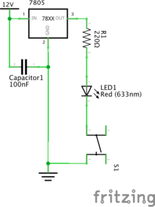
https://wp.nyu.edu/shanghai-ima-interaction-lab/category/recitations/
Above is the video of it working.
Circuit 3: Dimmable Lamp
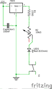
https://wp.nyu.edu/shanghai-ima-interaction-lab/category/recitations/
Above is the video of it working.
Processes
When building the first circuit, my partner and I encountered two major problems. The first one was that we didn’t pay attention to the different function of the three legs of the LM7805 voltage regulator. We found the pinout diagram and solved this problem. The second was how we didn’t make good use of the special design of the breadboard, and our circuit was a mess. One of the LAs passed by and explained to us how we could insert the red line and ground line of the power source into the left side of the breadboard and make the entire left side into the power line. After we successfully finished the first circuit, the remaining two circuits turned into a piece of cake and we were able to finish them without making any mistake.
Reflection on the questions
Question 1
I think the circuits we built in the recitation were not interactive. They were too basic and not smart enough to be interactive. The only interactivity between the circuits and us were the feedbacks we got from the output parts of them. Whether the buzzer made noise or whether the LED lit was hardly communicating. Therefore, they were not interactive in the way described in The Art of Interactive Design. But the process of building them was interactive for my partner and me. We ‘alternately listen, think, and speak’ to each other and together, we finished the work.
Question 2
I think it all starts with an interactive idea. You see a possibility to make something interactive, you have this idea. And with the help of some design and delicate application of technology, you create a piece of interactive art.

 A device that helps organize one’s mind when one is new to building circuits. Electronic components can be easily interconnected by inserting their ‘legs’ into the holes of a breadboard. The holes are connected with each other by certain rules like there are wires embedded under.
 This is used to obtain an output voltage that is friendly to the buzzer and LED we use.
 This serves as the output of the first circuit we build. When applied with a sufficient amount of current, it gives a noise indicating that the circuit is working.
 I am not entirely sure what it does in our circuit, but I know that it has something to do with storing electrical energy.
 This is a resistor whose resistance we can control. In the third circuit, it serves as a way to control the brightness of the LED.

