Lab report 3 (Molly)

  1. Assembly

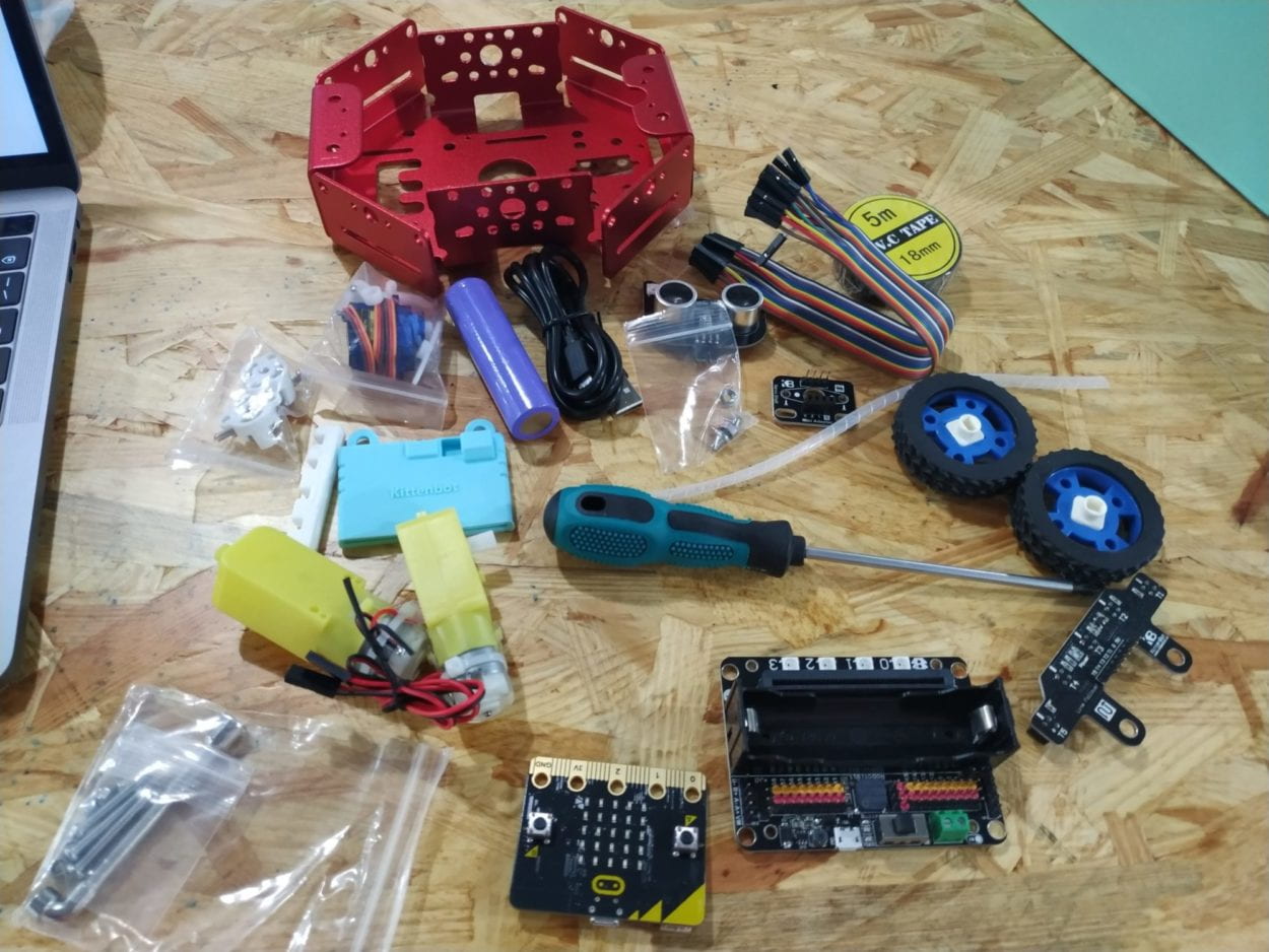
All the components laid out. When I was assembling, one nut wouldn’t catch on and I spent almost half an hour struggling with it with the lab assistant. At last, I figured out that it was broken by default. I ‘m impressed by my perseverance as well as my stupidity of not trying to think that there is something wrong with the nut.
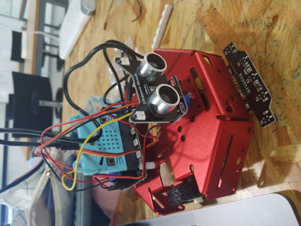
2. Testing sensors

(1)Speaker (on the micro:bot)

(2)Neopixel

(3)DC motors

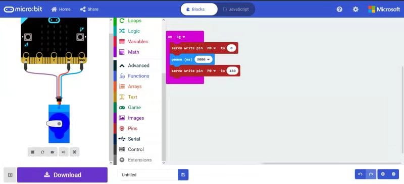
(4)Servo (of the kitten’s head)

3. Building a robot that can avoid obstacles using ultrasonic

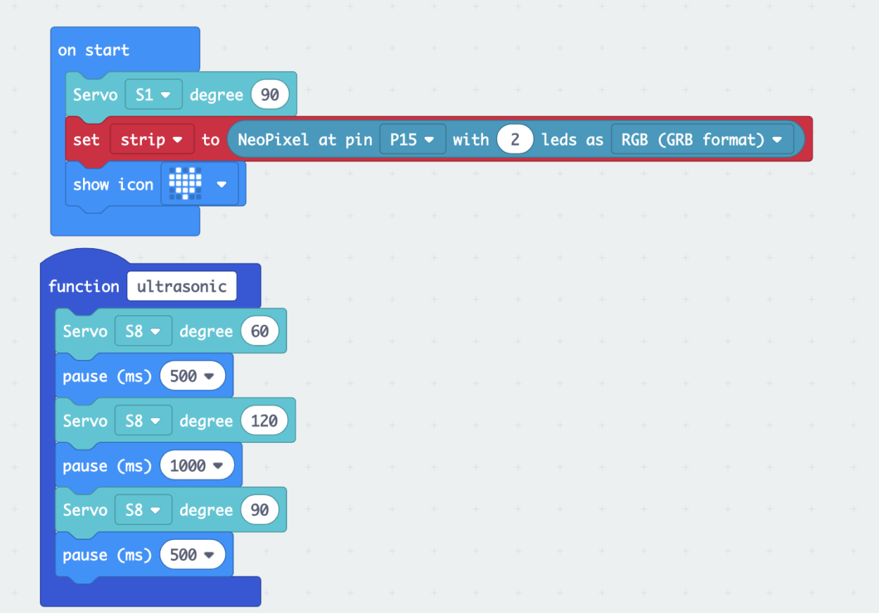
(1) The robot at first could only stop in front of the obstacles. It’s because I copied the code from https://www.kittenbot.cn/products/robotic/. And missed the part of “pause for 500ms”.

(2) I added the command and adjusted it into “pause for 400ms” to allow the robot to turn left 90 degrees every time it meets an obstacle. The adjustment is made because motors’ power is different from each other. The part of the robot stops at the obstacle, shakes its head and turn the green light red is also making it more vivid. 

These are the final codes.
 

Reflections:

The robot could only turn at a certain degree. It couldn’t find its way through. Moreover, the ultrasonic only guarantees a sight at its parallel, if the obstacle is smaller or taller, it may not detect and thus run into it.
Recitation 2:Arduino Basics by Molly (Weiyi He)

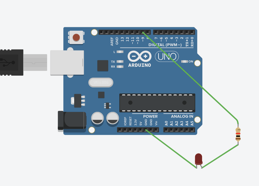
  1. Fade

Reflections:

1) I started to realize that actually, pins can provide power, just as pin 9 did in this circuit.

2)Led isn’t mirror, I have to pay extra attention to the direction–which leg should go to positive.

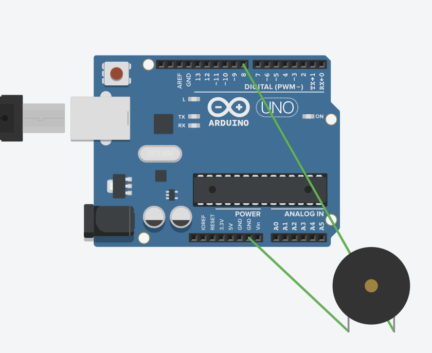
2. toneMelody

*Be careful how the legs are plugged to connect the wires correctly.

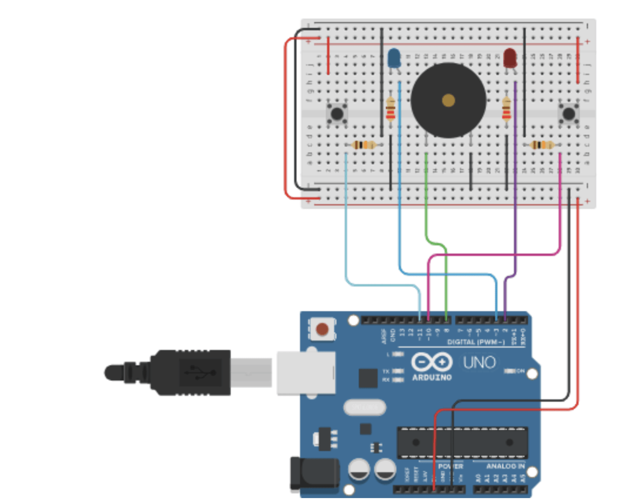
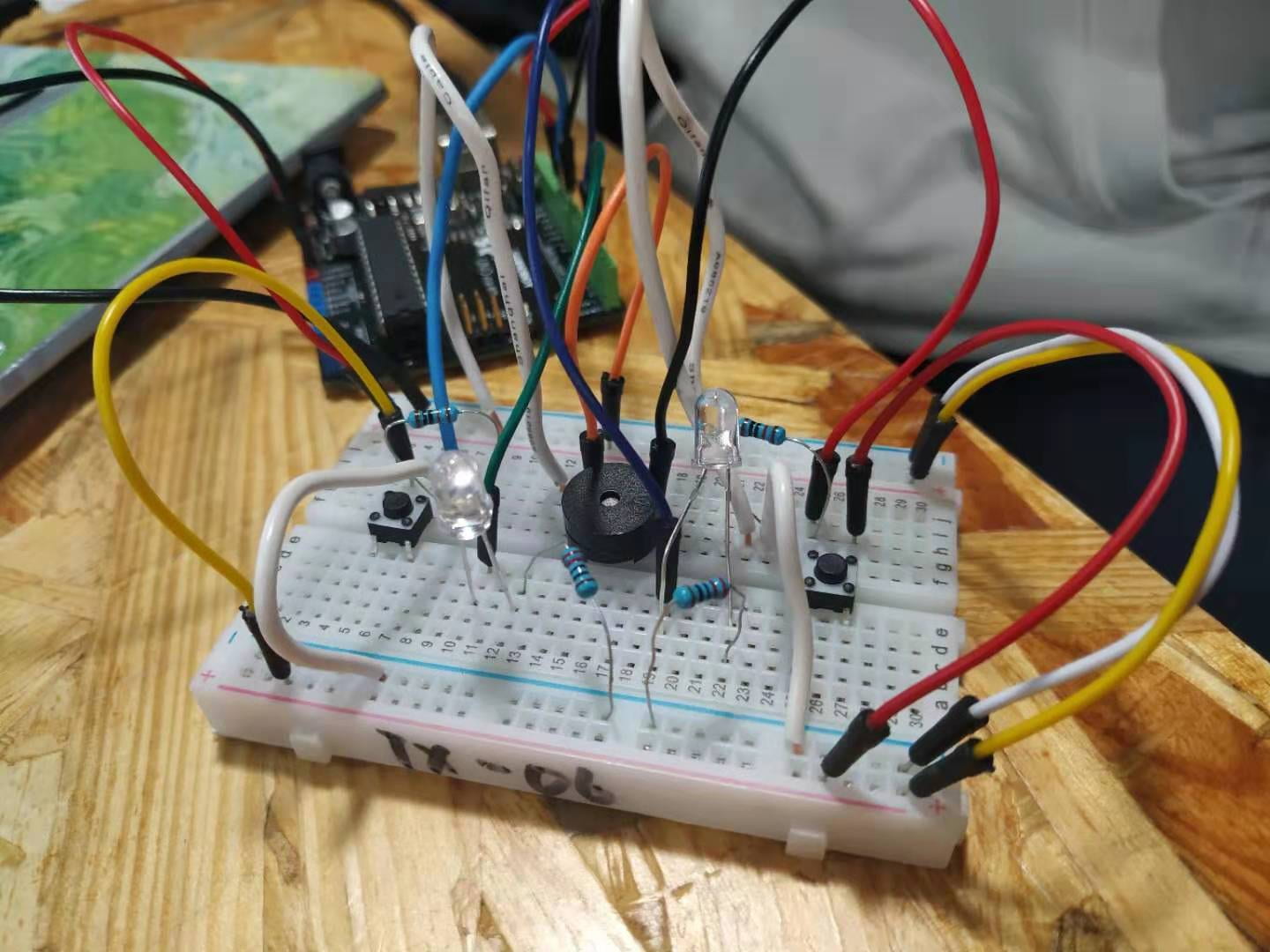
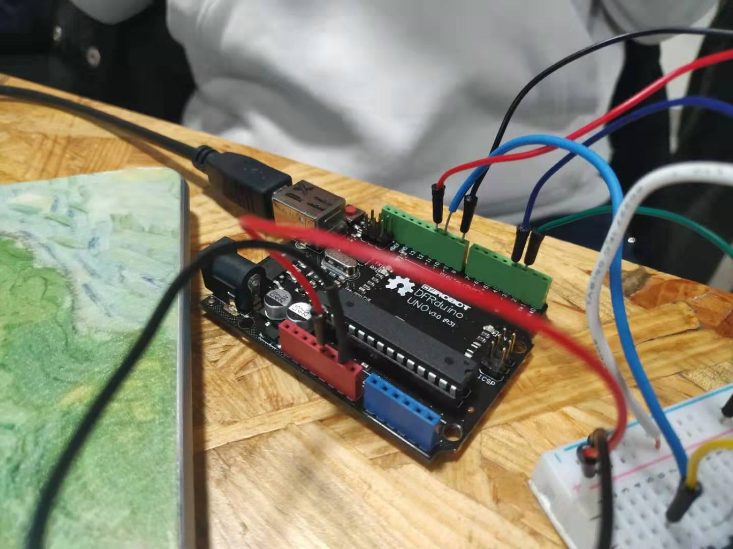
3. Speed game

(credit to: https://www.tinkercad.com/things/6MzvN5rlZlr-race-the-led-spring19)


Reflections: 

1) The circuit is rather complicated and there could be a short circuit. Therefore, double check the circuit before plugging into power. We had a short circuit and burnt a wire (maybe additionally, an LED). It led us to have a long time of debugging (finding where is wrong with the circuit)

2)When is debugging the circuit, certain strategies could be implemented. They are a reflection of one’s experience in dealing with circuits. So practice more, and I will become a more professional builder. And don’t be afraid of making mistakes.

4. Interaction is between various entities, one take an action, the other would give a response according to some conditions.

5. I want the 100,000 LEDs to be on a random street. It is a display of people’s emotions when one walk past them. This is when the most private part being showcased to the community of people that happen to be at the same spot or to pay attention to the person’s well-being. It could be a test of whether the surrounding people would take action toward the person’s emotions being displayed. It could also be research into how people mostly or randomly feel when they are walking on a random street.

Recitation 3: Sensor by Molly (Weiyi He)

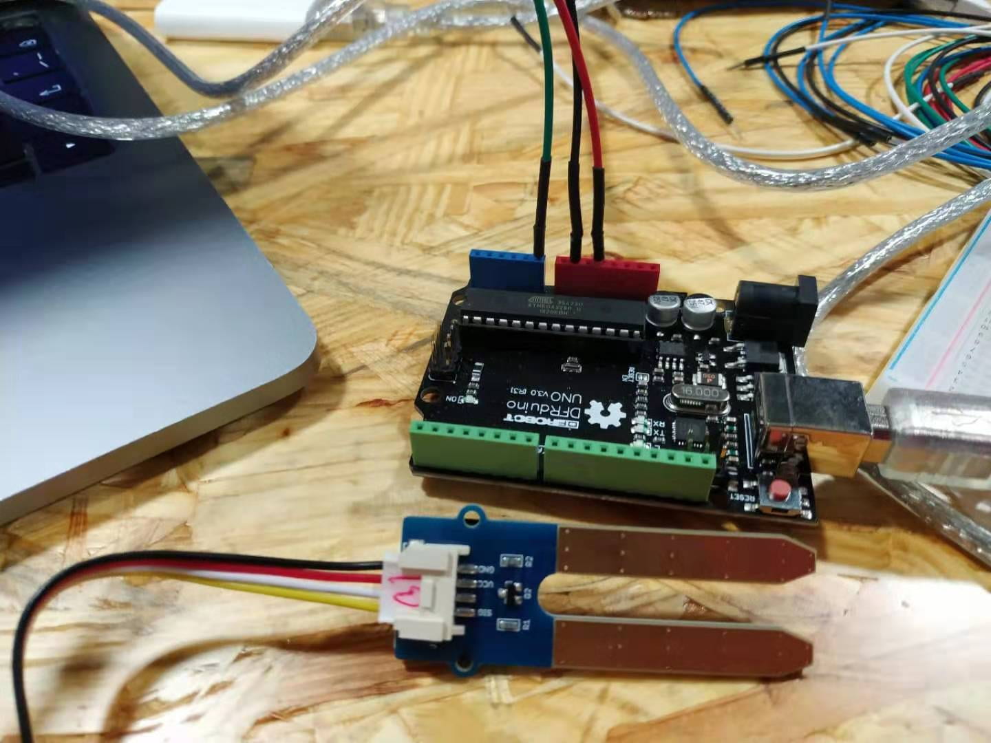
  1. Handshake tester–Moisture Sensor

I found out that if I hold my hand onto the sensor, it could detect my hand’s humidity. Therefore, I created a handshake tester– To determine whether your hand is too sweaty for handshakes. Anyone who wants to make friends can use this gadget.


(1) If your hand is not sweaty (sensorValue<=200), it would tell you “You are good to go~ Go and make a friend!”.

(2) If your hand is too sweaty(sensorValue<200), it would tell you “Your hand is too wet! Rub it! /n Press the reset button if you think you are ready!”.

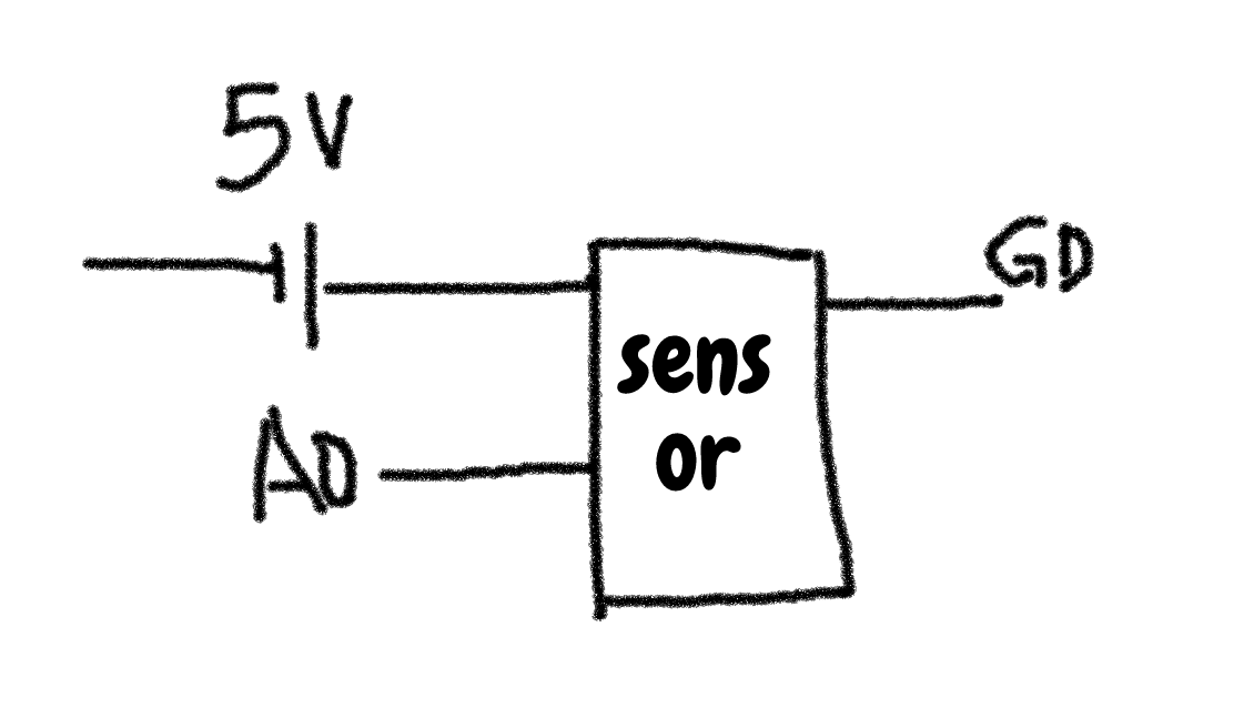
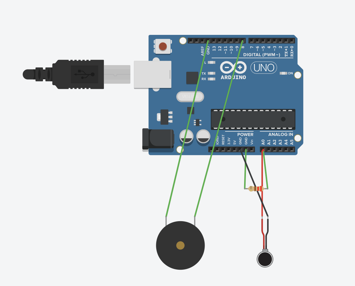
2. A doorbell that detects “knock”–Vibration sensor
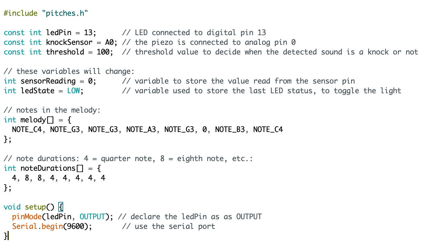
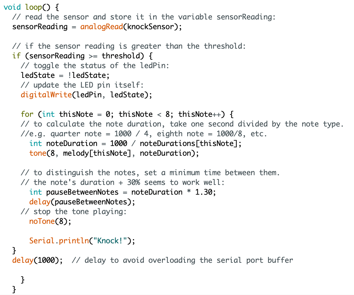
    This doorbell can detect whether someone is knocking on the door and gives out a doorbell ring, blinks the LED, and displays “knock!” *n onto one’s screen. This can help those people whose ears are a bit of insensitive to know whether someone is knocking. The 3 ways of reminding (light, words, and sound) help to make sure one notices it even if they are too observed in work.


The screen displays “knock!”*n when the vibration detects a “knock”.

The buzzer plays out a toneMelody and the LED blinks.

3. Coding is like implementing the idea into a language that the computer could understand. The idea shall follow a logical way. A scheme is similar to a program. There is this order of logic that requires coder’s clear knowledge of his idea.

4. The computer is penetrating into every corner of our life. Everyone could be replaced by the computer someday, as the artificial intelligence is growing, developing, and evolving at an incredible speed. Nowadays, computers become a daily object, a tool to all informative questions, a helper of many kinds of work.

Lab report 2 (Molly)

  1. Testing the light sensor

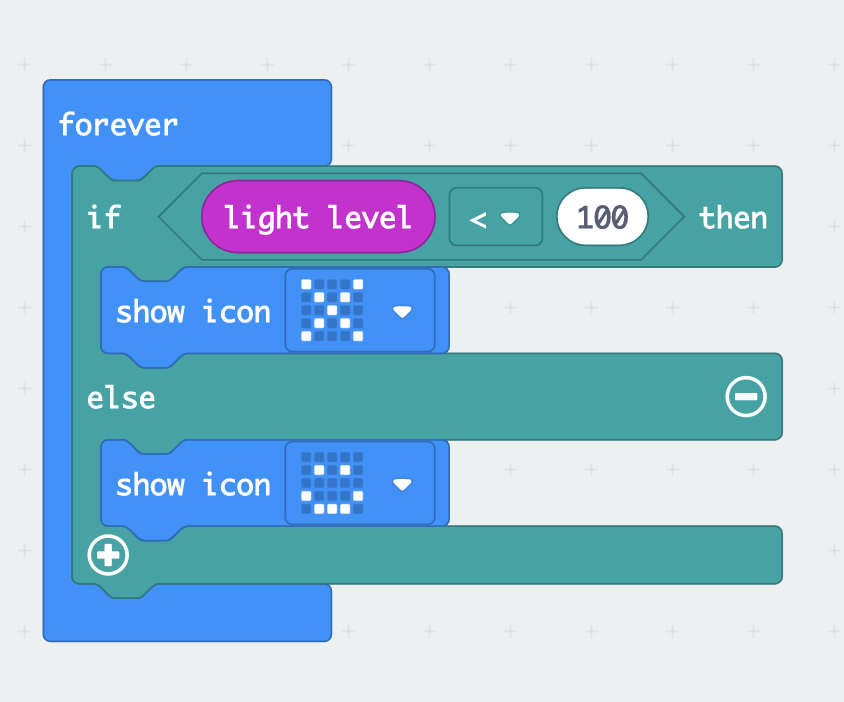
I discovered that the light sensor is at the front of the micro:bot, while other sensors such as the accelerometer and one more (perhaps the magnetic sensor) are at the back.

I opened the flashlight when filming. Therefore, when the camera gets closer to the micro:bot, the light level is higher and the smile shows up. 

2. Wireless communication

When the A button is pressed on the first board, the second board would show the number 0. The communication system is easy to establish, conveying numbers, strings, tuples, etc.

3. Animal behavior system

It imitates the natural behavior of the turtle’s retracting its head when facing danger. The program is simple, and the “turtle” is abstract as well. 

Reflection:
Given little time, we had to come up with these very basic ideas. Next time, I shall read and think about the lab template carefully before the class comes, so that deliberateness could be involved in the learning process.

Int Lab Recitation 1–Weiyi He(Molly)

Lab Date: Feb 15, 2019
Instructor: Marcela
Lab Partner:
 Sam Li

Aim of Today’s Lab: build three sets of circuits using the breadboard and learn how to solder.

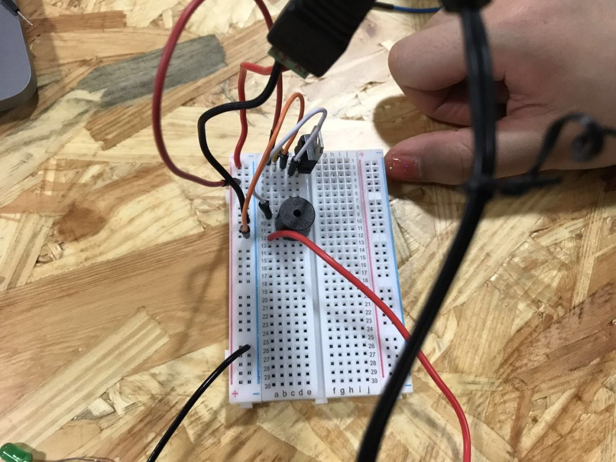
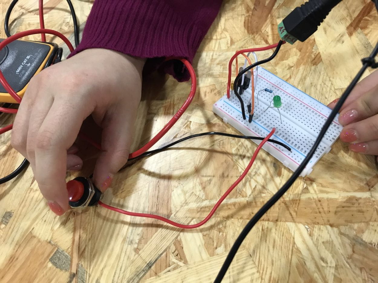
Circuit 1: Door Bell 

Components:

  • 1 * Breadboard–A pre-organized cable layout, easy to plug in jumper cables and other units’ legs. Good for organizing circuit. 
  • 1 * LM7805 Voltage Regulator–Turns 12V DC to 5V DC. This, with the power supply, gives our buzzer and LED a friendly 5V. 
  • 1 * Buzzer–Output. Add direct current and it plays a 2200 Hz pitch.
  • 1 * Arcade Button–Input. Switch on and the current can pass
  • 1 * 100 nF (0.1uF) Capacitor–Stores electricity while current is flowing into them, then releases the energy when the incoming current is removed. Capacitors can also be used to stabilize and smooth the flow of electricity.
  • 1 * 12 volt power supply–Turns 220V AC to 12V DC. 
  • 1 * Barrel Jack–Convert the power in the cable into the form that the breadboard can process with
  • Several Jumper Cables (Hook-up Wires)–Help with connecting the circuit

1

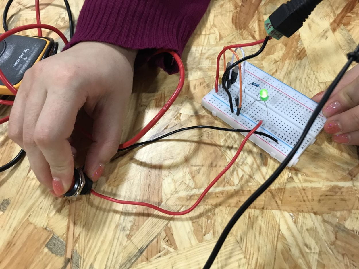
Circuit 2: Lamp

Components:

  • 1 * Breadboard
  • 1 * LM7805 Voltage Regulator
  • 1 * Arcade Button
  • 1 * 220 ohm Resistor–Help reduce the current and share the voltage so that the LED won’t pop.
  • 1 * LED–Output. Polarized. Consume electricity and emits light.
  • 1 * 100 nF (0.1uF) Capacitor
  • 1 * 12 volt power supply
  • 1 * Barrel Jack
  • 1 * Multimeter–Test the resistance of the resistors.
  • Several Jumper Cables (Hook-up Wires)

2

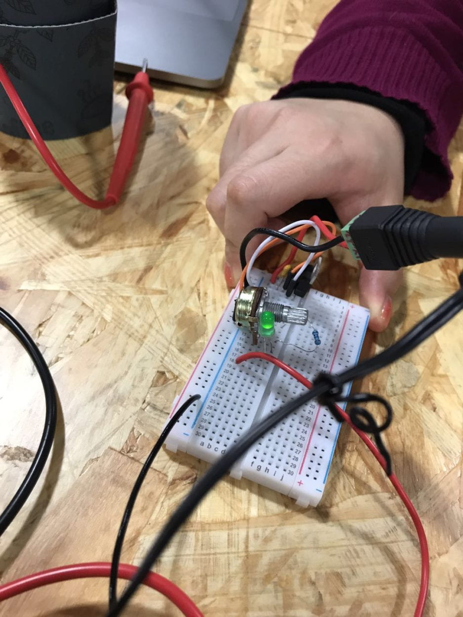
Circuit 3: Dimmable Lamp 

Components:

  • 1 * Breadboard
  • 1 * LM7805 Voltage Regulator
  • 1 * Arcade Button
  • 1 * 220 ohm Resistor
  • 1 * LED
  • 1 * 100 nF (0.1uF) Capacitor
  • 1 * 10K ohm Variable Resistor (Potentiometer)–Control the brightness of the LED using the change of the resistance.
  • 1 * 12 volt power supply
  • 1 * Barrel Jack
  • Several Jumper Cables (Hook-up Wires)

3

Problems:

  1. Don’t know which is the front of the capacitor: the front is with the black box that sticks out.
  2. The negative is seen as the ground.
  3. The power should better be inserted into the very left/right column with specific signs of +/-
  4. Each row should be connected with cables.
  5. The very left/right column is not connected to the middle two columns.
  6. Always plug out the device when altering the circuit.
  7. The capacitor is both in parallel and series connection.

We’d also tested the push-button switch and found out that of the 4 legs of the switch, the diagonal 2 work to serve as a switch.

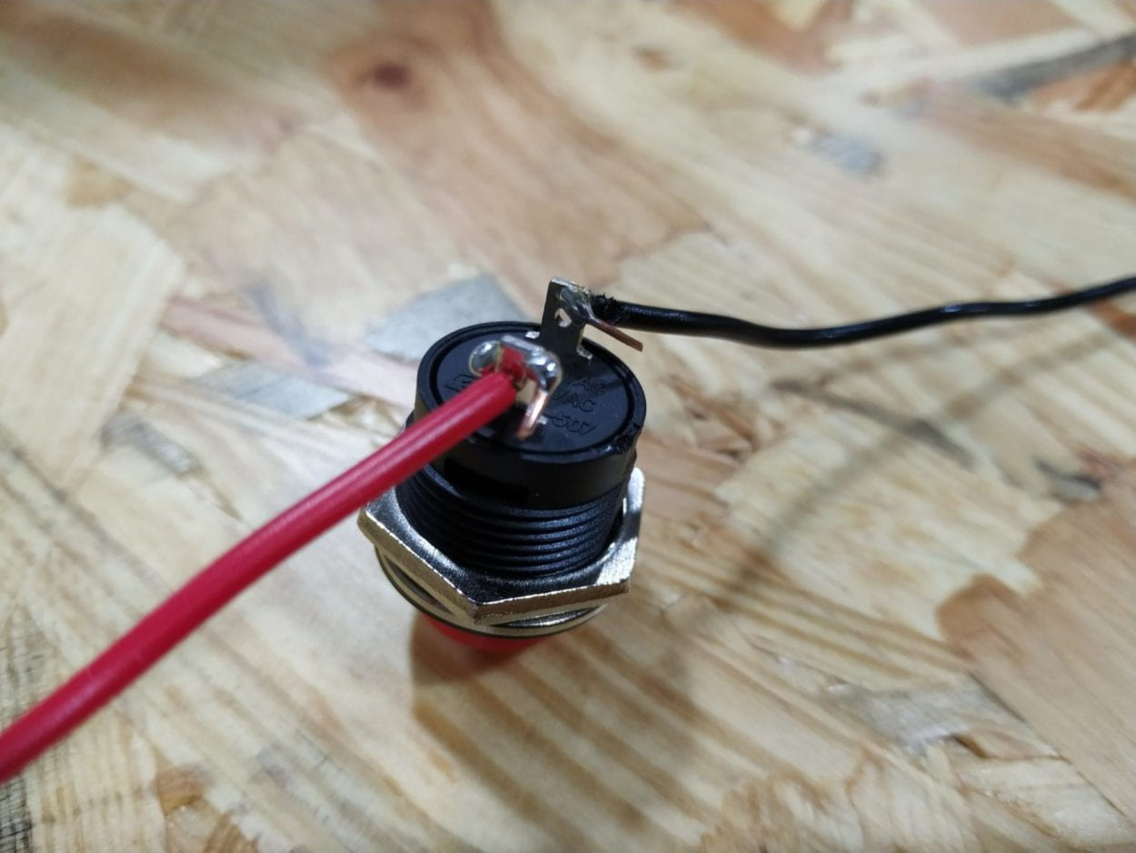
Soldering part

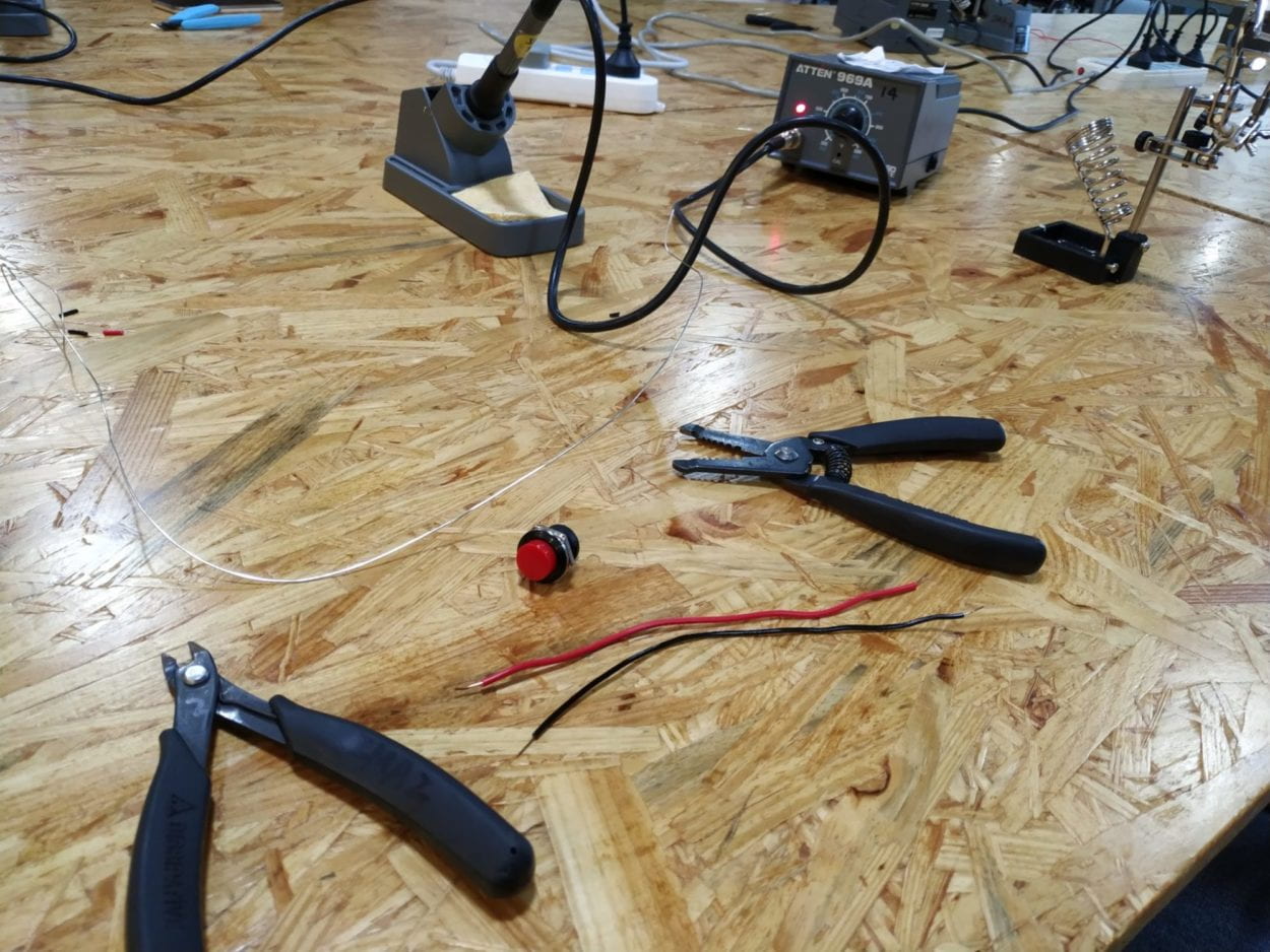
Tools:

Soldering iron: set to a specific degree

Soldering stand

Wire cutter and wire stripper

Problems:

  1. The tip of the soldering iron has some oxide coating and it increases the difficulty of melting the solder. To avoid failure, solder for a longer time/use steel wool to clean the oxide coating/don’t touch the oxidic parts of the iron 
  2. I burned some of the outer of the wire. Correction: Be careful.

Answers to the questions

1. For the first two circuits, if you push the button (or switch), the circuit gives feedback: either buzzing or lighting up the LED. For the third one, if you turn the handle of the potentiometer while you push the button, you can control the brightness of the LED. The users can interact with the buzzer/LED with the help of the circuit.

2.

Yayoi Kusama

Infinity Mirrored Room -The Souls of Millions of Light Years Away, 2013

wood, metal, glass mirrors, plastic, acrylic panel, rubber, LED lighting system, acrylic balls, and water
 
The result is a distinctly visual immersion and a counterpoint to the rooms that envelope the viewer. Through extreme repetition, it creates phenomenological experiences that provoke a sense of boundlessness and transcendence.