Project Proposal By Eric Shen

1. Project Title: Tree

Project Statement Of Purpose:

        For this project, our design is that when users interact with a real pot of soil ,or in other words, to take care of it by changing its physical conditions, like the moisture and the temperature of the soil. At the same time, there would be a projection of a tree right above the pot to make it the users feel like they are taking care of a real plant. The projection of the tree would grow or wither according to the interaction of users with the pot of the soil.  Based on the project called “Epilog” in my Preparatory Research and Analysis documentation, I found that interaction that can make changes in a projection is really interesting. In addition, there is a project in this video gave us inspiration.

 Beyond that, after reflecting on the midterm project, containing a variety of different interaction with project is really crucial to a successful project, therefore, we came up with the idea about using different sensors to detect and create different kinds of interaction instead of simply touching the walls which is shown in the video above. 

        There are a few challenges that we’ve thought about: how to select and install a  variety of sensors that detect different changes in the soil, how to draw a tree in Processing as lifelike as possible and how to make an animation of the tree’s changing in order to make the changing process of the tree look more smooth. When taking care of the virtual tree, those who don’t pay much attention to plants around us would understand that if plants are ignored by people and not taken good care of, they would lose their vigor and this notion can not only be applied to plants, but also it can apply to pets, friends, family members and even everything around us. 

2. Project Title:  Puppet

Project Statement Of Purpose:

        In this project, users can design a position of the puppet by themselves using the keyboard or a mouse and after that a real puppet controlled by servos and several strings would move for some time. Eventually, the movement of the puppet would stop at the exact position that is designed by users. The mechanism of the moving the puppet is inspired from the “Rechnender Raum” in the Chronus exhibition. 

        In order to make this project, we have to address challenges like figuring out the code for the servos to control the movement of the real puppet, the accurate transformation of data between Arduino and Processing and figuring out what different stand for in Arduino and Processing.  Through interacting with this project, we hope that the audience would identify with the puppet because we consider the puppet as a representative of those people who try to create a unique image of themselves and break their fixed images in front of others, but eventually fail due to the pressure coming from their life and other factors in their life. 

3. Project Title: One Minute

Project Statement Of Purpose:

        For this project, users would be asked to go inside a huge, dark and isolated box that contains light bulbs controlled by Arduino and a projector which would project stars made by Processing to the sides of the box and answer the questions that we recorded with either “Yes” or “No”. If the answer is “Yes”, then several light bulbs would be turned off while the stars projected would increase, and if the answer is “No”, the result would be the opposite.The light bulbs which are artificial light, represent the stressful and busy life, while the stars represent peace and the time for people to think. In the Chronus exhibition, there is one project that left a deep impression on me which is “Beholding the Big Bang”. When I first saw that project, I was lost in thought about how did everything come into being and what is the origin of the universe. Therefore, we want to do such an interactive project that can provoke other people’s thinking while adding more user-project interaction in it. And the reason why we embody these meanings in light bulbs and stars is that we got inspired from one line in the promotion of EarthHour: the less artificial lights in cities there are, the brighter the stars will be. 

        The challenges that we met encounter with in this project involve how to connect light bulbs instead of LEDs with Arduino, how to make users be clear with the underlying meaning of this project and how to arrange and decorate the space of the box in order to reach the expected visual effect.  This project intends to have an experience like meditation, listening to the question that we raised about their life and having a minute to reflect on themselves. This may remind users of how much they’ve spent on this fast-paced world, without having any time to ponder in silence alone without any external factors to disturb them and reflect on themselves. 
Recitation 7: Functions and Arrays by Eric Shen

Step 1

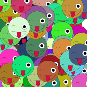
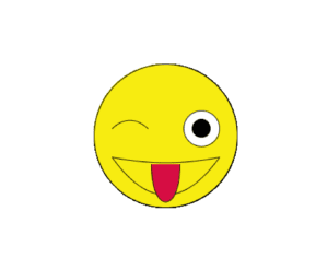
In step 1, we are asked to create some graphic of our own design using parameters such as x position, y position, and color. What I drew was a little  winking face

Code: 

float x = 0;
float y = 0;
float c = 0;
float a = 0; 
float b = 0; 
void setup(){
  size(800,800);
  background(255);
}

void draw(){

   winkingface(400,400,247,236,17);

}
void winkingface(float x , float y, float a , float b , float c ){
  
fill(a,b,c);
ellipse(x,y,200,200);
bezier(x-75,y+30,x-25,y+100,x+25,y+100,x+75,y+30);
bezier(x-75,y+30,x-20,y+40,x+20,y+40,x+75,y+30);
bezier(x-75,y-10,x-60,y-25,x-40,y-25,x-25,y-10);
fill(255);
ellipse(x+50,y-10,50,50);
fill(#D60D43);
bezier(x-20,y+40,x-20,y+110,x+20,y+110,x+20,y+40);//tongue
fill(0);
ellipse(x+50,y-10,25,25);
  
}
Step 1

Step 2:

(1)
If the for loop is placed in setup():

Code:

float x = 0;
float y = 0;
float c = 0;
float a = 0; 
float b = 0; 
void setup(){
  size(800,800);
  background(255);
for(int i = 0; i < 100; i++){
   x = int (random(width));
   y = int (random(height));
   c = int(random(255));
   a = int(random(255));
   b = int(random(255));
   winkingface(x,y,a,b,c);
}
}

void draw(){

}
void winkingface(float x , float y, float a , float b , float c ){
  
fill(a,b,c);
ellipse(x,y,200,200);
bezier(x-75,y+30,x-25,y+100,x+25,y+100,x+75,y+30);
bezier(x-75,y+30,x-20,y+40,x+20,y+40,x+75,y+30);
bezier(x-75,y-10,x-60,y-25,x-40,y-25,x-25,y-10);
fill(255);
ellipse(x+50,y-10,50,50);
fill(#D60D43);
bezier(x-20,y+40,x-20,y+110,x+20,y+110,x+20,y+40);//tongue
fill(0);
ellipse(x+50,y-10,25,25);
}
Step 2 (1)

(2)
If the for loop is placed in draw():

Code:

float x = 0;
float y = 0;
float c = 0;
float a = 0; 
float b = 0; 
void setup(){
  size(800,800);
  background(255);
}
void draw(){
for(int i = 0; i < 100; i++){
   x = int (random(width));
   y = int (random(height));
   c = int(random(255));
   a = int(random(255));
   b = int(random(255));
   winkingface(x,y,a,b,c);
}
}
void winkingface(float x , float y, float a , float b , float c ){
  
fill(a,b,c);
ellipse(x,y,200,200);
bezier(x-75,y+30,x-25,y+100,x+25,y+100,x+75,y+30);
bezier(x-75,y+30,x-20,y+40,x+20,y+40,x+75,y+30);
bezier(x-75,y-10,x-60,y-25,x-40,y-25,x-25,y-10);
fill(255);
ellipse(x+50,y-10,50,50);
fill(#D60D43);
bezier(x-20,y+40,x-20,y+110,x+20,y+110,x+20,y+40);//tongue
fill(0);
ellipse(x+50,y-10,25,25);
}

Step 3: 
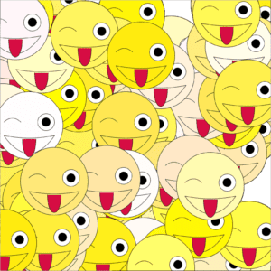
Create three Arrays to store the x, y, and color data.  In setup(), fill the arrays with data using a for loop, then in draw() use them in another for loop to display 100 instances of your graphic

float[] x = new float[100]; 
float[] y = new float[100];
float[] a = new float[100];
float[] b = new float[100];
float[] c = new float[100];

void setup(){
  size(800,800);
  background(255);
     for(int i=0; i<x.length; i++){
   x[i] =random(width);
   y[i] =random(height);
   a[i] =random(230,255);
   b[i] =random(255);
  }
}
void draw(){
for(int i = 0; i < 100; i++){
   winkingface(x[i],y[i],a[i],b[i]);
}
}
void winkingface(float x , float y, float a , float b ){
  
fill(255,a,b);
ellipse(x,y,200,200);
bezier(x-75,y+30,x-25,y+100,x+25,y+100,x+75,y+30);
bezier(x-75,y+30,x-20,y+40,x+20,y+40,x+75,y+30);
bezier(x-75,y-10,x-60,y-25,x-40,y-25,x-25,y-10);
fill(255);
ellipse(x+50,y-10,50,50);
fill(#D60D43);
bezier(x-20,y+40,x-20,y+110,x+20,y+110,x+20,y+40);//tongue
fill(0);
ellipse(x+50,y-10,25,25);
}
Step 3

Step 4: Add individual movement to each instance of your graphic by modifying the content of the x and y arrays.

float[] x = new float[100]; 
float[] y = new float[100];
float[] a = new float[100];
float[] b = new float[100];
float[] c = new float[100];

void setup(){
  size(800,800);
  background(255);
     for(int i=0; i<x.length; i++){
   x[i] =random(width);
   y[i] =random(height);
   a[i] =random(230,255);
   b[i] =random(255);
  }
}
void draw(){
for(int i = 0; i < 100; i++){
   winkingface(x[i],y[i],a[i],b[i]);
   x[i] += random(-5, 5);
   y[i] += random(-5, 5);
}
}
void winkingface(float x , float y, float a , float b ){
  
fill(255,a,b);
ellipse(x,y,200,200);
bezier(x-75,y+30,x-25,y+100,x+25,y+100,x+75,y+30);
bezier(x-75,y+30,x-20,y+40,x+20,y+40,x+75,y+30);
bezier(x-75,y-10,x-60,y-25,x-40,y-25,x-25,y-10);
fill(255);
ellipse(x+50,y-10,50,50);
fill(#D60D43);
bezier(x-20,y+40,x-20,y+110,x+20,y+110,x+20,y+40);//tongue
fill(0);
ellipse(x+50,y-10,25,25);
}

Question 1: In your own words, please explain the difference between having your for loop from Step 2 in setup( ) as opposed to in draw( ).

If the for loop is in the setup(), It would only run once. Therefore the variables are fixed,  leading to the static graphic. While if the for loop is in draw(), it would run over and over again, every time it runs, the variables change as well, leading to the moving graphic. 

Question 2: What is the benefit of using arrays?  How might you use arrays in a potential project?

Using arrays allows us to store a great number of variables, and it could potentially save our time from doing tedious work like setting the variables over and over again. I could use array in my project if I want to draw numerous shapes like I did in the recitation. It could also be used when I try to choose one number as an output of a game among a certain group of numbers. 

Preparatory Research and Analysis by Eric Shen

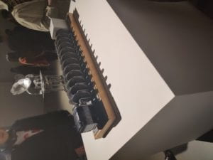
        Before I went to the Chronus exhibition, I only attended non-technology based art exhibition such as Pompidou art exhibition. I found that the initial intention of every exhibition is to let the audience identify with the artists and to know what the artists are trying to express through their artwork. This was also included in my experience in the Chronus exhibition. When I was trying to understand the projects in the Chronus exhibition, I focused more on how these projects worked with application of various technology which was similar to my attempt to find out what means of artistic expression are used in non-technology based art exhibition.As for the “Beholding the Big Bang” project made by Arthur Ganson, its appearance was merely some gears rotating at different speed and some of them were even still. After careful observation and reading the introduction of the project, I had a feeling of being suddenly enlightened. I understood that there was a motor that drove those gears which reduced the motor speed so that the final gear would take 13.82 billion years to rotate once.

Beholding the Big Bang

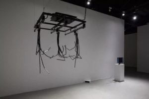
The reason why my experience in the Chronus exhibition was unique to me was that every project in this exhibition contained a lot of interactions either with itself or with the audience, which normally would not exist in non-technology based art exhibition. Take the project that’s called “Artificial Intuition” made by Zhang Hua, the audience’s movement would be displayed on the screen in the corner and the branch-like machine would react to the movement accordingly.

Artificial Intuition

 This interactive experience would not take place in other non-technology based art exhibition for the reason that audience can just statically appreciate the art pieces that would not make any response to any of behavior.

Research

The two projects that I chose for my research were “Epilog” by Schnellebuntebilder and “Hertzian Landscapes” created by Richard Vijgen. I would argue that the “Epilog” is the project that better aligns with my understand of a good interactive project compared with “Hertzian Landscapes”. To begin with, my personal understanding involves three things.
1. It has to involve reciprocal actions that generate on-going effects on each other and  contain physical input and output to each other as well.
2. The interaction between the project and the users should be obvious and easy for the users to detect and understand. It is better if  the interaction is between the project and users directly.
3.  the users should know the purpose of why they are interacting with the project with as least instruction as possible, thus knowing what they want to achieve through the interaction and understanding what outcomes would take place resulting from their actions. 
        As for the “Epilog”, it satisfies all the three needs that I think of for a successful interactive project .This project is basically a room installation that uses light, sound and haze to create a 25-minute constantly transforming world of moving images and sounds according to the visitors’ own moving pattern. For one thing, the user-project interaction is easy to understand because  the stunning shadow and light effect that is projected on the ground would change dramatically in response to the users’ movement. Both of the mutual on-going effect on both the user and the project and users’s purpose of keeping interacting with it are both  clear: when users move, the lighting and shadowing effect would change accordingly and on knowing the result of their actions, users would continue to change their movements in order to explore how many effects their actions could cause. 

Epilog

        However, for the “Hertzian Landscapes” project, it is a live visualization of the radio spectrum. It includes a digital receiver to scan large swaths of radio spectrum in near real-time and using Three.js visualises thousands of signals into a panoramic electromagnetic landscape. If we just evaluate this project only in terms of its interaction without taking its practical use into account, it is definitely not as good as the “Epilog”. For one thing, the interaction is between the radio spectrum and the display screen without any user-project interaction. As users, the only thing that they could do is to stand in front of the project and observe the change of the screen. The interaction is very difficult to understand for the reason that if one want to understand exactly how the display screen would change according to the change of the radio spectrum, one must know the some professional knowledge about these concepts. Therefore, the interaction in this project is difficult to understand which doesn’t align with my understanding of a successful interactive project. 

Hertzian Landscapes

        My original definition of “interaction” is : a cyclic process in which at least two characters alternatively input from the physical world, process and output based on my group project and the previous research. During the process of working on my midterm project and learning from the comments on my project, I found that a good interactive project should lay more emphasis on perfecting the interaction between the project and the users based on the users’ perspective. Therefore, a straightforward interaction that users could easily understand is a necessary component of a good interactive project. According to a quote in the article called “Making Interactive Art: Set the Stage, Then Shut Up and Listen”: “Your task in designing an interactive artwork is to give your audience the basic context, then get out of their way.”In order to let the users explore the project without feeling at lost at one point on their own, the interaction should be as straightforward enough. Beyond that, the users should know how their actions would cause a series of change directly, which means that they need to get instant feedback,  in order to take the interacting experience with users to the next step.  Another thing is that the users should know why they should complete such interactions with the project, in other words, users should be given a sense of purpose when interacting with projects. 

Bibliography

“Making Interactive Art: Set the Stage, Then Shut Up and Listen – Hello.” Accessed November 7, 2019. http://www.tigoe.com/blog/category/physicalcomputing/405/.
“Hertzian Landscapes – The Interactive Space of a Radio Spectrum / @richardvijgen.” Accessed November 7, 2019. https://www.creativeapplications.net/js/hertzian-landscapes-the-interactive-space-of-a-radio-spectrum/.
“Epilog – Interactive Light and Shadow / by @schnllbntbldr.” Accessed November 7, 2019. https://www.creativeapplications.net/vvvv/epilog-interactive-light-and-shadow/.

Recitation 6: Processing Animation by Eric Shen

Recitation exercise:

During the recitation, we were asked to use Processing to create an animation that has certain interactions with either keyboards or mouses. I was inspired by the rotation of windmills, therefore, I was hoping to create something with simple shapes that looks similar to windmills and when I click the “UP” key, it would rotate clockwise and when I click the “DOWN” key, it would rotate counterclockwise.  In order to make the shapes in Processing start to rotate, I found that in the class slides, there is a function called “rotation”. I started to learn this function by myself. According to the slide, the code that is shown can only draw the same shape in a different angle. It’s more like a picture instead of an animation. So I did a further research about how to use this function in making an animation. I found out that I need to add other functions to achieve the effect that I want. For the purpose of making a rectangle pivoting on a certain point, I need to use the three functions mentioned below:
pushMatrix();
translate();
popMatrix();

This is the code of my work: 

int x = 50;
int speed = 0;
int i = 0;
void setup(){

size(600,600);
colorMode(HSB);
}
void draw(){
int val = frameCount ;
background(0);

if(key==CODED){
if(keyCode==UP){
val=frameCount%360;
}
if(keyCode==DOWN){
val=-frameCount%360;
}
}
if (x == 50) {
speed = 1;
}
if(x == 100) {
speed = -1;
}
x=x+speed;
if(i<255){
i=i+1;
}
if(i>=255){
i=0;
}
fill(i,200,300);
noStroke();
pushMatrix();
translate(300, 300);
rotate(radians(val));

rect(50, 50, x, x);
popMatrix();

pushMatrix();
translate(250, 300);
rotate(radians(val));
rect(0, 50, x, x);
popMatrix();

pushMatrix();
translate(250, 250);
rotate(radians(val));
rect(0, 0, x, x);
popMatrix();

pushMatrix();
translate(300,250);
rotate(radians(val));
rect(50, 0, x, x);
popMatrix();

pushMatrix();
translate(100, 100);
rotate(radians(val));

rect(50, 50, x, x);
popMatrix();

pushMatrix();
translate(50, 100);
rotate(radians(val));
rect(0, 50, x, x);
popMatrix();

pushMatrix();
translate(50, 50);
rotate(radians(val));
rect(0, 0, x, x);
popMatrix();

pushMatrix();
translate(100,50);
rotate(radians(val));
rect(50, 0, x, x);
popMatrix();

pushMatrix();
translate(500, 500);
rotate(radians(val));

rect(50, 50, x, x);
popMatrix();

pushMatrix();
translate(450, 500);
rotate(radians(val));
rect(0, 50, x, x);
popMatrix();

pushMatrix();
translate(450, 450);
rotate(radians(val));
rect(0, 0, x, x);
popMatrix();

pushMatrix();
translate(500,450);
rotate(radians(val));
rect(50, 0, x, x);
popMatrix();
}

Here is the actual look of my work

Additional homework

We were asked to create an ellipse that its color of the stroke and its scale has to be periodically changing and its position is controlled by keyboard’s arrow key input. 

Step 1

The first step is pretty simple, so I managed to do it smoothly. 

Step 1

Step 2

The second step is very similar to an in-class exercise that we did. “if” structure and a variable”x” that stands for the diameter of the ellipse are used in this step in order to make it periodically expand and contract.

Step 2

Step 3

I followed the instruction about the colorMode() function in Processing Website. I set the colorMode to HSB and set a variable that stands for the each color in HSB. 

Step 3

Step 4

It’s easy to figure out the fourth step because the only thing that we need to do is to follow the instruction in the class slide about the keyCode() function. We need only to code the keys with “UP”,”DOWN”,”RIGHT” and “LEFT” and another two variables that could control the x and y coordinates of the ellipse.

Step 4

Added Bonus

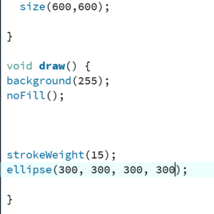
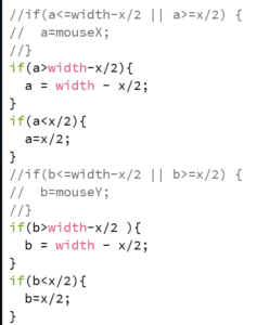
When I first considered how to achieve this step, the first thing that came in my mind was that I had to constrain the x and y coordinates of the ellipse in a certain range. Whenever the coordinates are bigger than the width or length, the x coordinate would be width, the y coordinate would be length. Therefore, I used two “if” structures to achieve that.  But after I did that, I realized that I omitted another situation which is the possibility that the coordinates of the ellipse would be smaller than 0. Then, I added another two “if” structure to constrain the range of the coordinates from 0 to 600. Due to the ellipse has its radius, and the radius is periodically changing, I set the range from x/2- 600-x/2. When I run this code, it did have the function of making your canvas’ edges a border, but when the ellipse is moving along the edge, it would not stick closely to the edge. Yet I haven’t come up with a solution to that. 

Code for added bonus

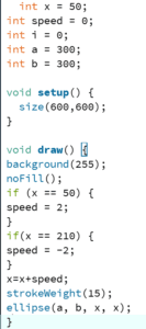
This is the complete code for the homework

int x = 50;
int speed = 0;
int i = 0;
int a = 300;
int b = 300;

void setup() {
size(600,600);
colorMode(HSB);
}

void draw() {
background(255);
noFill();
if (x == 50) {
speed = 2;

}
if(x == 210) {
speed = -2;

}
x=x+speed;
if(i<255){
i=i+1;
}
if(i>=255){
i=0;
}
stroke(i,200,250);
x=x+speed;

strokeWeight(15);
if(key == CODED){
if(keyCode==RIGHT){
a=a+3;
}
if(keyCode==LEFT){
a=a-3;
}
if(keyCode==UP){
b=b-3;
}
if(keyCode==DOWN){
b=b+3;
}
}

//if(a<=width-x/2 || a>=x/2) {
// a=mouseX;
//}
if(a>width-x/2){
a = width – x/2;
}
if(a<x/2){
a=x/2;
}
//if(b<=width-x/2 || b>=x/2) {
// b=mouseY;
//}
if(b>width-x/2 ){
b = width – x/2;
}
if(b<x/2){
b=x/2;
}
ellipse(a, b, x, x);
}

This is the final version of my homework

List of functions

Rotate();
pushMatrix();
translate();
popMatrix;
colorMode();

During this recitation, I’ve learned a lot of useful function to create an animation in Processing, such as rotate() and colorMode(). These functions would be very useful in my future designs. Also I learned how to use conditions like “if”structure to achieve certain effects and requirements for the animation. 

Recitation 5: Processing Basics By Eric Shen

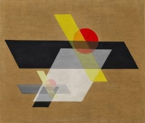
When I was trying to choose the motif, I browsed through the Bauhaus School of Arts.

Motif

This is the image that I select as the motif of mine. The first time I saw this image, I felt that this image could be associated with ancient Chinese paintings which makes me describe them as quaint. The light brown background looks like the color of the rice paper used for those ancient Chinese paintings. The color with the transparency feature reminds me of the hazy view that is peaceful. The red circles look like sun to me and the black parallelograms seem like shadows while the yellow ones resemble sunlight.

My work
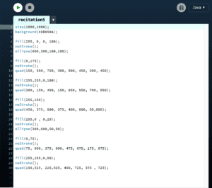
My code

The similarity between my work and the motif is that the same shapes are used in them. Yet there are distinct differences between them as well. To begin with, I modified the angle of the parallelograms in the motif in order to make coding the coordinations of them easier. For another, the background color in my work was not the same as that of the motif for the reason that I don’t know how to apply the transparency effect to the background color in Processing. In addition, there is difference between the proportion of the shapes. 

For me, I think processing could be a very good means of realizing my design since it could draw any shape and curves with the right code and even make animation. Yet it requires precision when we are designing the coordinations of each shape, which is very complicated and time-consuming based on my experience. Therefore, it requires very precise and careful plan before start to write any code. The reason why I regard Processing as complicated is probably that I was not very used to using this software. 

Bibliography

Guggenheim. “A II (Construction A II),” January 1, 1924. https://www.guggenheim.org/artwork/2979.