Recitation 4: Drawing Machines by Tiana Lui

3.15.19

This week we created drawing machines by using an H-bridge to control stepper motors attached to mechanical arms. First, I individually completed Step 1 and Step 2, assembling a circuit using the SN754410NE IC and the pre-installed Arduino Stepper Library. Next, I paired up with Monika to complete step 3, the drawing machine.

Materials:

For Steps 1 and 2

1 * 42STH33-0404AC stepper motor
1 * SN754410NE ic chip
1 * power jack
1 * 12 VDC power supply
1 * Arduino kit and its contents

For Step 3

2 * Laser-cut short arms
2 * Laser-cut long arms
1* Laser-cut motor holder
2 * 3D printed motor coupling
5 * Paper Fasteners
1 * Pen that fits the laser-cut mechanisms
Paper

Step 1: Build the circuit

H-bridge circuit diagram

//Code for stepper_oneRevolution

#include <Stepper.h>

const int stepsPerRevolution = 200; // change this to fit the number of steps per revolution
// for your motor

// initialize the stepper library on pins 8 through 11:
Stepper myStepper(stepsPerRevolution, 8, 9, 10, 11);

void setup() {
// set the speed at 60 rpm:
myStepper.setSpeed(60);
// initialize the serial port:
Serial.begin(9600);
}

void loop() {
// step one revolution in one direction:
Serial.println(“clockwise”);
myStepper.step(stepsPerRevolution);
delay(500);

// step one revolution in the other direction:
Serial.println(“counterclockwise”);
myStepper.step(-stepsPerRevolution);
delay(500);
}

Notes: I built the circuit using the diagram provided and using the practical knowledge that I gained in previous interaction lab lectures. For example, there are many pins that are connected to ground and to power. I remembered in our previous lectures that we connected GND to one of the negative vertical strips on the breadboard, then connected other GND wires to that negative vertical strip. For power, I connected one pin to power, then connected other wires to the row that pin was on, etc in succession. 

H-bridge is the IC roach. The semicircular notch on top indicates the top of the roach. The jack on the bottom represents the power jack where you plug in the 12v power supplier. 

The box on the right is the stepper motor. Try not to touch the stepper motor as it can get hot.

I first uploaded the stepper_oneRevolution into my Arduino, then connected my Arduino to an external USB and plugged my power supplier into the jack. I did not plug my Arduino into my computer USB port, because I don’t think my computer has a surge protected USB port. 

Step 2: Control rotation with a potentiometer

// Code for motorKnob

#include <Stepper.h>

// change this to the number of steps on your motor
#define STEPS 200

// create an instance of the stepper class, specifying
// the number of steps of the motor and the pins it’s
// attached to
Stepper stepper(STEPS, 8, 9, 10, 11);

// the previous reading from the analog input
int previous = 0;

void setup() {
// set the speed of the motor to 30 RPMs
stepper.setSpeed(30);
}

void loop() {
// get the sensor value
int val = analogRead(0);
map(analogRead(0),0,1024,0,200);
// move a number of steps equal to the change in the
// sensor reading
stepper.step(val – previous);

// remember the previous value of the sensor
previous = val;

}

Notes: I added a potentiometer to the breadboard, not directly connected to the rest of the pins/ic circuitry. I connected the potentiometer’s legs to GND, to a row with a pin connected to 5V (power), and to an analog input (A0). In the Arduino program, I changed the number of steps to 200 and added a map () function. The map function translates one scale of numbers to another scale of numbers. For example, The Arduino’s ADC (analog to digital converter) can read 1024 levels between 0V and 5V, and so the value returned by the analogRead function is an integer in the range 0 through 1023. Using map, you can scale the value back to a smaller range, which might be more helpful when specifically measuring voltages.

Step 3: Build a drawing machine

Notes: Monika and I had a hard time adjusting the position of the stepper motors so that the pen would touch the paper. The stepper motors wanted to fall over because there were two different motors rotating in different directions at different speeds. 

Question 1:
What kind of machines would you be interested in building? Add a reflection about the use of actuators, the digital manipulation of art, and the creative process to your blog post.

I would be interested in building machines that serve as aesthetic pieces but also have a purpose. For example, I’d like to build an electronic animal that is happy (indicated by a display or blinking lights or a wagging tail etc) when it vacuums (eats) pencil shavings. 

According to Wikipedia, “An actuator is a component of a machine that is responsible for moving and controlling a mechanism or system, for example by opening a valve. In simple terms, it is a “mover”. An actuator requires a control signal and a source of energy.” I can see a lot of uses for actuators, as much mechanical energy requires the moving of gears to generate power. Actuators are a very critical component to making electronic devices.

I think that the digital manipulation of art allows for increased creativity and the intersection of two fields: art and technology. Whereas studio art is limited to paint and pencil, digital manipulation expands the tools people can use to create art. Digital manipulation also produces a different aesthetic than traditional modes of art production, leading to a whole new style of art. Lastly, the ease and access to digital manipulation have democratized the photo, as digital manipulation gives everyone the power to add something new, edit,  input their own creative thoughts, and create something new.

I think that the creative process is a very exciting process, where the person creating is understanding and figuring out the connections between his or her ideas, exploring all possible thoughts and imaginations, paring it down, and coming out with a better, well thought out outcome. I also think it’s intriguing to explore different creative thought processes for different fields of study. For example, in writing, the general process is to free-write, reflect and solidify your thoughts and arguments, write, and then revise. For creating films, the director finds inspiration from life, creates a pitch/sizzle, writes a script, and prepares a shot list. Graphic designers create mood boards and web designers create wireframes. While all these pipelines have their own nuances, they are similar in that they ask the designer to come up with as many ideas as possible, conduct research (internal self reflection or external sources), choose which ideas are the best, generate a rough draft, and then constantly revise. I think that knowing a variety of frameworks for creative generation is beneficial because having multiple frameworks allows the designer to make more connections and understand their project even better.

Question 2:
Choose an art installation mentioned in the reading ART + Science NOW, Stephen Wilson (Kinetics chapter). Post your thoughts about it and make a comparison with the work you did during this recitation. How do you think that the artist selected those specific actuators for his project? 

Shawn Decker’s Scratch Series is, “a sound installation that explores the rhythm of scratching. The floor and wall pieces each have piano wire scratchers controlled by embedded microcomputer controlled motors. The controllers pull the scratchers back and forth against the surfaces to reflect patterns from nature or physics. Complex rhythms arise as the devices adjust to one another’s sounds.” 

Similar to the drawing machine we created during recitation, Decker’s project also had machines using tools to draw (or scratch) another surface. However, Shawn Decker’s project focused less on visual output and more on audio output, while our project’s goal was to create a visual drawing. Decker also explored an added theme of utilizing man-made machines and materials to mimic natural processes, which allows users to also reflect on the relationships between humans and machinery and nature. 

Because the project involves the moving of lightweight objects at varying intensities, I think Decker selected an actuator that isn’t too heavy duty but could handle different weights and could give him precise control over speed. 
Tiana Lui group project individual blog post on interaction

According to Crawford, interaction is, “interaction: a cyclic process in which two actors alternately listen, think, and speak.” In more technical terms, “If we want to get academic, I suppose we could replace listen, think, and speak with input, process, and output….” After reading his text, my interpretation of interaction is the receiving, processing, and communication between two or more parties/objects.

One interactive project that aligns with my definition of interaction is Alias. Alias is an electronic device that connects to a simple app in which users can “ train Alias to react on a custom wake-word/sound, and once trained, Alias can take control over your home assistant by activating it for you. When you don’t use it, Alias will make sure the assistant is paralyzed and unable to listen by interrupting its microphones.” 

This is an example of interaction because Alias receives information (the custom wake word sound), processes/thinks about it, then makes a decision (yes- turn the mic on, or no- paralyze system). This is a low-level interaction because the message received is simple, the thought process is binary, and the final decision is either yes or no.  

Most of our interactions with computers are low-level interactions. “In the case of most desktop computers, this means a mouse, a keyboard, a monitor, and speakers. To such a computer, we might look like a hand, with one finger, one eye, and two ears” (Igoe and O’Sullivan). Igoe and O’Sullivan argue for more and varied types of interaction, which would lead to higher level interactions. 

One “interactive” project that does not align with my definition of interaction is Phos.

“Phōs is an interactive web project by Daria Jelonek which deals with the complexity of light, room and time. It shows 24 hours of light in different places of the world. It is both an homage to natural light and aesthetic experience of light.”

The reason Phos does not fit my definition of interaction is because it is simply composed of flashing images of light. As Crawford says, talking to a brick wall is not interaction, because the wall is not interpreting your message, and the wall is not giving you an intelligible response. Similarly the rooms and videos in Phos do not process nor communicate information back to us; these inanimate and static objects do nothing with the information they receive from us. Videos tend to generally be non-interactive, because they are pre-recorded, and are unable to receive the information (ie. our reactions) that we send to it.

Phos likely got its “interactive” tag because it involves multimedia projections, is time-based, and allows audience members to actually be a part of/step into the project/artwork/ exhibition. Interactive nowadays is often used to describe exhibits where people can utilize other senses and touch and command parts of the exhibit. However, for Phos, people are not given the opportunity to influence or edit the video playing, hence, Phos does not align with my definition of interaction.

Our group focused on creating a more realistic, educational tool for those who read Braille. The project responded to my new understanding of high and low-level interaction, and my realization that there is still a vast amount of input and output that can be utilized in interaction. While the current Braille system is based around static, non-differential series of raised dots, we designed our Braille system around an intelligent fabric of the year 2119, which would change/mimic textures, allowing the user to have an added dimension (higher level of interaction) of touch experience by envisioning and connecting other life experiences to words’ meanings. Helen Keller’s teacher, Anne Sullivan, taught Helen Keller to read this way, placing Keller’s hands under a running faucet to teach Keller the meaning of the word “water”.

We didn’t alter the dot system used by Braille, because Braille is already a very accessible, well-established system that is easy to use, and because Braille was created based on the fact that blind people had a hard time “reading” raised alphabetic letters. Things that work for the average person may not work for those with disabilities, and if a designer only focuses on his own mindset/ideas, without considering the needs of their user base, he will never create an improved product.

One issue that our project could focus more on is accessibility. We geared our project to 2nd-4th graders because of the educational aspect, but our project could potentially expand to create an even more accessible world for the vision impaired. One way we could do this is instead of creating a system based on touch, we could create a network of sound, expanding and changing the function of our system to suits blind people’s needs beyond the classroom. For example, we could place our systems around traffic lights, guiding the blind by voice when they are crossing the road.

The readings and group project greatly increased my understanding of interaction, and will greatly impact the way I design interactive projects in the future.

Works Cited

https://www.creativeapplications.net/objects/alias-a-teachable-parasite-for-your-smart-assistant/

https://www.creativeapplications.net/news/phos-an-interactive-web-project-which-deals-with-the-complexity-of-light-room-and-time/

https://s3-ap-southeast-1.amazonaws.com/ima-wp/wp-content/uploads/sites/3/2017/08/05164121/The-Art-of-Interactive-Design-brief.pdf 

https://drive.google.com/file/d/1uviCK0V71cQpA76PV9PK03Df14vcsd0y/view 

Recitation 3: Sensors By Tiana Lui

3.1.19

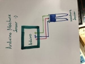
Moisture Sensor: The Moisture Sensor can be used as if you were doing a simple analog read. Connect the sensors’ power and ground pins to the Arduino’s power and ground, respectively. This sensor’s signal pin can then be connected to an analog input pin.

pictures of circuits   

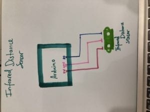
Infrared Distance Sensor: Similar to the Moisture Sensor, the Infrared Distance Sensor can be used by implementing the connections and code from a simple analog read sketch. In the case of Infrared Distance Sensors, using the “map()” function can be helpful. This function maps the analog readings from the sensor to the distance between the sensor and the object.

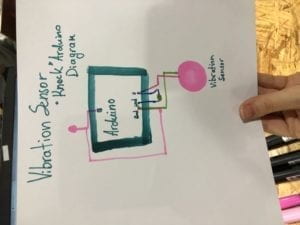
Vibration Sensor: To create a Vibration Sensor you will need a piezo disk and a 1 mega ohm resistor. You can use the Knock example (Arduino>File>Examples>0.6Sensors>Knock). Otherwise, the Vibration Sensor can be used as a simple Analog input. If you use this sensor, please add a different output to your circuit, aside from the built-in LED.

Question 1:
What did you intend to assemble in the recitation exercise? If your sensor/actuator combination were to be used for pragmatic purposes, who would use it, why would they use it, and how could it be used?

I intended to assemble various electronic circuits involving sensors. For the vibration sensor, I intended to create a system that would respond to a knock input. If my sensor was used for pragmatic purposes, the vibration sensor could be used by a guitarist, to detect the vibrations of a guitar, and perhaps tune the guitar. 

For the infrared distance sensor, the sensor would respond to interference from 4-30 meters away. A pragmatic purpose for this sensor would be as a night light, for those who have trouble seeing in the dark at night.

As for the moisture sensor, a very well known example would be to use it for people with plants, having the moisture sensor measure the humidity levels of the soil, regulating the moisture levels for the plant.

Question 2:
Code is often compared to following a recipe or tutorial. Why do you think that is?

Code is used to write programs. Programs are step by step instructions that tell the computer to execute certain functions. Recipes are also step by step instructions but telling others how to cook. 

Question 3:
In Language of New Media, Manovich describes the influence of computers on new media. In what ways do you believe the computer influences our human behaviors?

The computer influences our human behaviors by altering our routine habits. Computers have become many people’s productivity tool, and many people rely on computers to function and get work done. Computers have also allowed us to share enormous amounts of information, and this saturation of sharing has spurred an obsession with showing our best sides and taking the perfect selfie. The computer encourages an increased amount of screen time and an increased amount of sharing, in a new way, via the internet.

Recitation 2: Arduino Basics by Tiana Lui

2.22.19

Materials

1 * Arduino Uno- A single-board microcontroller for building digital devices and interactive objects that can sense and control both physically and digitally.

1 * USB A to B cable- A cord that attaches the Arduino to the computer, allowing the computer and Arduino to communicate with each other.

1 * breadboard

1 * buzzer

2 * LEDs

2 * 220 ohm resistors

2 * 10K ohm resistors

2 * pushbuttons- A switch.

2 * arcade buttons- A switch.

A handful of jumper cables

1 * Multimeter (optional)

Circuit 1: Fade

https://www.arduino.cc/en/Tutorial/Fade

Code: Arduino>File>Examples>03.Analog>Fading

Circuit 2: toneMelody

https://www.arduino.cc/en/Tutorial/toneMelody

Code: Arduino>File>Examples>02.Digital>toneMelody

Circuit 3: Speed Game

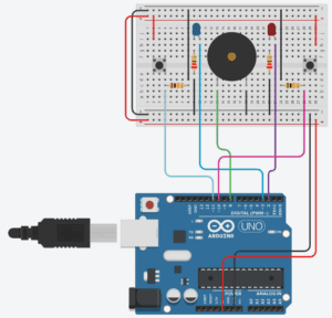
This is a two player game where each participant races to click a button more than their opponent. After 10 seconds, whoever has clicked their button the most and fastest wins! To play the game, open up the Serial Monitor in Arduino IDE. To start the game over, press the Reset button on your Arduino Board.

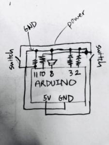
speed game diagramspeed game circuit drawing

(including your own drawing of the schematic for circuit 3).

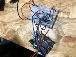
speed game breadboard image

(Optional) Circuit 4: Four-player Speed Game

Pair up with another group and modify the circuit and code to make the speed game from circuit 3 a four-player game. 

Notes

Circuits 1 and 2 were relatively simple to build. At first, circuit 1 didn’t work due to the circuit becoming loose and wires coming undone.

Lessons learned: the wires come out of the breadboard easily. Make sure everything is secure before testing the functionality of the circuit.

Circuit 3 was a bit more complicating. There were more wires to connect. I learned that to use the other side of the breadboard, you can connect the ground and power to the other side’s ground and power.

Because there were images of the Arduino board, building the circuits were straightforward and didn’t require much thinking. In general, I learned that the electrical components are always attached to an output, ground, and the power source in some way. However, translating the circuit to the schematic and vice versa was harder. 

We (Kathy, Sam, Monika, and I) tried to build the four-person speed game but didn’t get to finish it. 

Question 1:

Reflect how you use technology in your daily life and on the circuits you just built. Use the text Physical Computing and your own observations to define the interaction.

I use technology as a productivity tool, using such programs as google docs, and google drive. I also use technology for entertainment and communication, visiting digital content websites such as youtube, and using Facebook and email to communicate with my friends. 

Until reading, Introduction to Physical Computing by Igoe and O’Sullivan, I did not realize that the only method of input/interaction with the computer I was using was typing, which involves solely my fingers, eyes, and hands. After reading the text, I would define this type of interaction as limited interaction, and that there is so much more involvement that can be done between the human and the computer, and interactive computing, AR, and VR are changing our limited interactions to more immersive and full-bodied experiences.

Question 2:

If you have 100,000 LEDs of any brightness and color at your disposal, what would you make and where would you put it?

If I had 100,000 LEDs of any brightness and color, I would choose all white LEDs and make an adaptable hanging display that resembles stars in the sky, blinking fireflies, or falling rain. The display can be hung indoors or outdoors, ideally under a skylight window if hung indoors, thereby combining nature and electronics. 

Or, I would utilize the LEDs in a performance like this. https://www.youtube.com/watch?v=305ryPvU6A8 

Recitation 1: Electronics and Soldering By Tiana Lui

Author: Tiana Lui, Class: Interaction Lab, Professor Cossovich

2.15.19

Components of the circuits: what they do and why are they included

1 * Breadboard- this is where the circuit is connected by wires. The breadboard connects components of a circuit together. A completely connected circuit is necessary for the circuit to work.

1 * LM7805 Voltage Regulator- Voltage regulators maintain a constant voltage level. They are important because many electronic devices only work properly within a certain range of voltage, and voltage regulators can make sure the voltage supplied in the circuit stays within that optimal range.

1 * Buzzer- A buzzer is an electrical device that converts one type of power to audible sound. 

1 * Push-Button Switch- Switches are a control that can be used to interrupt the flow of current through a circuit. A pair of contacts within the switch are connected or disconnected depending on the physical position of the switch. When connected, the circuit is complete, and can execute tasks. When disconnected, the circuit is unattached, and the electronics do not execute anything.

1 * Arcade Button- Another type of switch.

1 * 220 ohm Resistor- A resistor is a two-terminal electrical component that resists the flow of electricity, and can be used to control the flow of current.
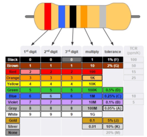
Resistors are marked with a series of colored stripes which indicate their amount of resistance.

1 * LED- Light-emitting diodes are a type of diode which can act as a visible or invisible light source. They are frequently used as indicator lamps in many electronic devices, or collectively as a display.

1 * 100 nF (0.1uF) Capacitor- Capacitors store electricity while current is flowing into them, then release the energy when the incoming current is removed. Capacitors can also be used to stabilize and smooth the flow of electricity.

1 * 10K ohm Variable Resistor (Potentiometer)- A resistor with the ability to change and control how much resistance to electrical current that programmer wants.

1 * 12 volt power supply- The power supply provides the power for the circuit to conduct electricity.

1 * Barrel Jack- Barrel jacks are electrical power connectors used for attaching extra-low voltage devices such as consumer electronics to external electricity. This is needed because we need a way to connect our circuit to power in order for there to be electricity/power to make the circuit run. 

1 * Multimeter- Multimeters can measure the current, voltage, and resistance of objects. They are useful for identifying the correct components with the correct current, voltage, and resistances to place into your circuit. 

Several Jumper Cables (Hook-up Wires)- Wires connect the circuit together. Without wires, electronic components are detached and the circuit is unable to work, because only a completely connected circuit will work.

Diagrams of the circuits

Below are the schematics of the circuits we built. The first one is a doorbell circuit, the second is a circuit of an led lamp, and the final circuit is a dimmable lamp circuit. 

doorbell

lamp

dimmable light

My notes

This was the first class we used the breadboard.

Initially, the breadboard was confusing to use, because we didn’t know what wires went where.

The picture of how the breadboard works helped us (the breadboard is composed of two strips of metal on the side and rows of metal on the inside).

We found out how to translate the circuit drawing to the breadboard.

So, to translate drawing to circuit, identify power source (12v this time).

Tip: keep power source wires on the side of breadboard (on the two vertical metal strips)

In this case, power source has two wires, one for power and one for ground

Continue connecting things to those immediately next to it in the drawing

If in the drawing, something is next to ground, connect component to ground on breadboard.

If in the drawing, something is adjacent to both power source and ground, connect component to both ground and power source.

Voltage regulator had a 3 pins, and the order in which it was connected to other components mattered. The way to distinguish the pins is to understand that the bulky part (package) was the front. Knowing this made it easy to identify the order of the pins that corresponded to the drawing.

Keep the capacitor close to the voltage regulator. For some reason, the circuit will work better this way. Why?

Make sure the buzzer is in line with your wires. The buzzer is bulky and bigger than the width of the pins you input, so make sure to check that you put your wires next to the pins.

Tip: keep the buzzer slightly tilted/not all the way in to double check the positionings of its pins so you can accurately place wires next to those pins

There are different ohm resistors. You can check their color codes or use the multimeter to measure their ohms. color codes for resistor

The multimeter reading didn’t work for us as the number kept jumping around. Need to understand how to properly get a multimeter reading. Also need to keep in mind conversions between units (ie. ohms and kiloohms)

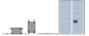
The switch has an orientation. It should be placed horizontally, (longer side connects on same row)

Picture of correct and incorrect orientation of switch on breadboard

Unplug the power source every time before you move wires around, otherwise components can get fried and damaged.

We were only able to complete 2 circuits. We didn’t test out the push button we soldered.

Soldering (pretty straightforward)

There’s a machine that controls the temp of pen and makes a pen super hot, a stand for your soldering pen which has a cleaning sponge to clean the pen, metal wire you melt onto the two things you want to connect, a wire stripper, wire cutter…

The pen thing just gets really hot so you can melt metal.

Always clean pen (stab it on the sponge) to preserve its longevity and prevent rust.

A good solder is even and connects the two places you want to connect

Strip a bit of the end of wire, connect it to other part, solder by melting wire with pen, the melted metal should touch both exposed wire and other part.

Don’t breathe in fumes, they are toxic

Aren’t we supposed to have masks and some sort of vent/fan that captures/draws away the toxins???

Other advice

Most times, if circuit is good, double check the position of your capacitor?

Pictures and Video Captures

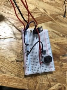
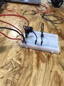
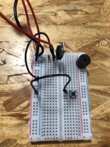
doorbell circuit completed doorbell circuit WIP doorbell circuit WIP

LED lamp circuit

Question 1:
After reading The Art of Interactive Design, in what way do you think that the circuits you built today include interactivity? Please explain your answer.

According to The Art of Interactive Design (Crawford), there are low and high levels of interaction. Since the circuits we built on Friday were relatively simple and only performed one task upon execution/under our influence, the circuits could be considered low-level interaction. However, the code and time required to build these circuits are much more complicating, and so our interaction with the circuits are relatively high and long. It is very challenging to define whether something is interactive or not, as there is no consensus on the scope of interaction. Does opening the refrigerator count as interaction, or does it count as talking to a brick wall? Does interaction only count when there is feedback both ways? And what type of feedback is qualified to be “interactive”? These are questions that need to be answered first before anything can be defined as interactive or not.

That said, the circuits we built on Friday, have various instances of interaction. For example, a human finger (analog input) pressing a button, causing the circuit to connect and complete. Or, the breadboard circuit communicating with the computer/arduino software, causing the electronics to execute actions. We also interacted with the hardware, placing wires into the breadboard, however, in that moment, the breadboard was not attached to the computer, hence, the breadboard gave no feedback, and may not count as interaction. We also interacted amongst ourselves, communicating with each other on how best to build the circuit. Above are examples of interaction, where two things that came in contact with one another produced some sort of action or communication.

Question 2:
How can Interaction Design and Physical Computing be used to create Interactive Art? You can reference Zack Lieberman’s video or any other artist that you know. 

Interaction is about two or more things connecting, and communicating something to each other or spurring some sort of action to be executed. Physical computing is great for interactive art because physical computing is about making an electronic device communicate with computer software to perform some sort of action, a process that is already interactive. Interactive art using physical computing is also scalable, in the sense that the programmer can start by programming a low-level interaction, then move on to coding more complex interactions, generating higher-level communication and engagement between the computer, user, and artwork.

Physical computing can be combined with any type of interest to form an interdisciplinary study, so it is not unusual that physical computing is combined with art. One such artist, Zach Lieberman uses interactive media to explore the relationships between technology, performance, and the body. He has created projects including an open-source eye-tracking system that allows disabled artists to draw using their eyes, and a performance that includes drawn sketches that react to a visitors’ touch. 

In summary, the world is your oyster. It is up to your imagination to use physical computing to create interactive art.