Lab/Recitation 4 – Sarah Waxman

Materials: 

For Steps 1 and 2

1 * 42STH33-0404AC stepper motor

1 * SN754410NE ic chip

1 * power jack

1 * 12 VDC power supply

1 * Arduino kit and its contents

For Step 3

2 * Laser-cut short arms

2 * Laser-cut long arms

1* Laser-cut motor holder

2 * 3D printed motor coupling

5 * Paper Fasteners

1 * Pen that fits the laser-cut mechanisms

Paper

The first thing I did was build a circuit made to control the stepper motor and order it to rotate once and complete a revolution. To achieve this I used Arduino’s example code “stepper_oneRevolution.” This step ran smoothly without any hiccups.
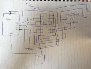
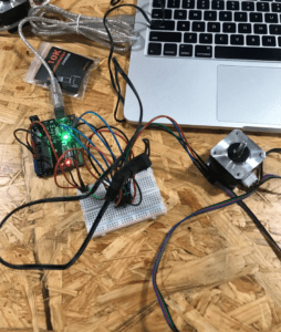
 

The next step was to control the rotation of the stepper motor by adding a potentiometer to the circuit in such a way that I could read the analog input, and by adjusting Arduino’s “MotorKnob” example code to conform to the motor’s capacity. I thereby changed the number of steps to 200, by adding “val = map(val, 0, 1023, 0, 200);”.

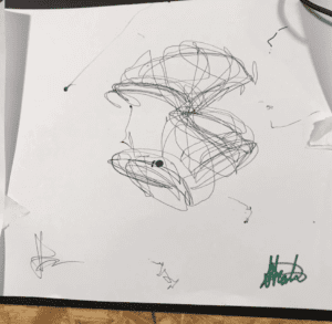
For the third step, I paired up with Tristan to build the drawing machine. We combined our circuits from the first two steps and put together all the materials needed for the drawing machine. The circuit worked perfectly, our only issue was machine not holding the pen/marker firmly enough to make any real strokes on the paper. We solved this by taping the pen onto the machine. 
Sarah Recitation 4 -1

Question 1:

I would be interested in building machines mostly for the sake of entertainment, and perhaps for professional use. The employment of actuators for the digital manipulation of art has caused a revolution in the world of art in general, as it has created an entire new genre of contemporary art: digital artwork. Moreover, it has added an entirely new and important step to the creative process in the form of programming as well as the interaction that must be facilitated for the digital artwork to function, one way or another. For instance, a painting with a light that changes state based on the distance of the viewer would have to be programmed in order to function this way. Furthermore, a certain type of drawing machine would undoubtedly be useful in the professional sense to architects, for example, as they often must draw geometric shapes drawn very exactly to scale — something that a plain human hand could not normally do.

Question 2

Daniel Palacios Jimenez’s “Waves” employs mechanical rotational actuators in order to create its desired effect. The actuator-controlled rope responds to the type of motion the machine senses around it: in response to regular and slow movement, it creates simple sine waves, and in response to a lot of motion it forces the ropes to reflect that in the form of complex irregular waves and sounds. This is very interesting to me as it really pulls the viewers into the work of art. 

Our drawing machine similarly involved rotating actuators in order to control and move the pen/marker a certain way. The drawing/movement of the pen reflected the movements of or hands on the potentiometer that was controlling the direction of the drawing machine.  When we would switch the directions  of the motor in quick succession the drawing would reflect this by making short and chaotic strokes. 

Lab/recitation 2 – Sarah Waxman

Recitation Exercise: 2

Partner: Santiago Salem

Materials:

1 * Arduino Uno

1 * USB A to B cable

1 * breadboard

1 * buzzer

2 * LEDs

2 * 220 ohm resistors

2 * 10K ohm resistors

2 * pushbuttons

2 * arcade buttons

A handful of jumper cables

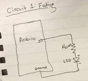
Circuit 1: Fading

This circuit was fairly simple to build as it required few components (a resistor, an LED, and two cables) and a program already existing as an example on the Arduino app on the computer. We did not come across any problems in building this circuit. 

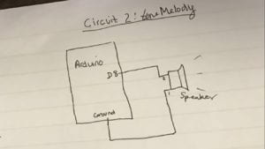
Circuit 2: toneMelody

This circuit was similar to circuit 1, as we simply replaced the LED with a speaker and changed the program to another existing Arduino “example” program in order to have the speaker emit a melody. 

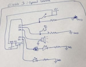
Circuit 3: Speed Game

This circuit was a lot more complicated as it involved many more components (some superfluous, i.e. all the extra jumper cables for the sake of pure design) and a much more complex program we obtained from TinkerCad. This circuit took a significantly longer time for us to build partly because we kept running out of jumper cables and having to go cut some more, and largely due to the fact that we encountered to major issues with our assembly. The first was that we neglected the polarity of one of the LEDs — we were able to identify and rectify this problem relatively quickly. The second and more significant issue was that we had a short circuit, so the USB port in the computer would not accept the connection because of the overflow of electricity coming from the Arduino that would have damaged the computer. After we fixed this problem, we were finally able to successfully run the program and play the game. The TinkerCad source for the program of this game can be found following this link: https://www.tinkercad.com/things/6MzvN5rlZlr-race-the-led-spring19. 

Question 1

In my daily life, I use computers in the laziest way possible; the only action required of me is from my fingertips and my attention. In this case (lab), we used a combination of a multimedia computer and a micro-controller which both interacted with each other following our interaction with them in order to output the ultimate goals: for the LED to fade, for the speaker to play the melody, and for the speaker and LEDs to indicate the progress of the speed game’s players. The speed game is an example of parallel events, as each player’s ability to quickly and repeatedly click the button was measured simultaneously and individually until the time was up, at which point the program would count the player’s numbers against each other to determine the winner and light their side’s LED. Interaction is the combination of both an action and a reaction, that either occur serially or simultaneously. 

Question 2

If I had a 100,000 LEDs of all colors and brightness, I would design a surface that would serve as either the wall (and obviously light) or the floor of a swimming pool. When turned on, it would light up all the LEDs and I’d program it so that certain color LEDs turn on and off periodically to create an interesting and cool effect that would be reflected through the water and that could be perceived from above the water’s surface. 

Lab/reciation 1 – Sarah Waxman

Materials:

  • 1 * Breadboard
  • 1 * LM7805 Voltage Regulator
  • 1 * Buzzer
  • 1 * Push-Button Switch
  • 1 * Arcade Button
  • 1 * 220 ohm Resistor
  • 1 * LED
  • 1 * 100 nF (0.1uF) Capacitor
  • 1 * 10K ohm Variable Resistor (Potentiometer)
  • 1 * 12 volt power supply
  • 1 * Barrel Jack
  • 1 * Multimeter
  • Several Jumper Cables (Hook-up Wires)

Relevant Components: 

Capacitor: Necessary for the voltage regulator 

Voltage regulator: there to ensure that the voltage that reaches the resistor(s) and LED/speaker does not exceed the amount that it needs (which would result in those components being burnt). It reduces the initial voltage (12V) down (to 5V).

Resistor: functions to reduce the voltage that will ultimately reach the LED/speaker. 

Potentiometer: only in Circuit 3, serves as another resistor that can change the amount of voltage that it absorbs/that eventually reaches the LED so that the LED can reflect that amount as its brilliance. 

Switch/Button: function is to close the circuit; i.e. make the LED light up, speaker make a sound. 

Cables: used to connect all the components on the breadboard. 

12 volt: serves as the power supply that fuels the entire circuit 

Circuit 1
Circuit 2
Circuit 3

We did not encounter any issues with the circuits but once, when one of the cables erroneously connected two components on the breadboard (between the voltage regulator and the speaker in Circuit 1). We corrected this by unplugging the circuit from the power source (the voltage), and connecting the cable to the correct line on the breadboard to connect the 7805 to the speaker and then plugged the circuit back into power. The circuit then functioned properly. 

By definition a circuit includes interactivity. For the circuits to function correctly, all the components must interact with each other. Moreover, there is a further interaction between the human and the circuit when the  person closes the circuit by clicking the switch/button, which initiates the ensuing continuous interaction between all the previously mentioned components that make the LED turn on, the speaker sound, etc. 

Interaction design and computing can be used to create interactive art by allowing the spectator to become a part of the art, or make the viewer a necessary component for the art to achieve its purpose. For example, an art installation that mirrors the viewer’s actions forces the viewer to become a part of the art’s ultimate purpose: this is an interaction between viewer and art and the computational design that is behind the artwork.