Recitation Serial Communications – Sarah Waxman

In both exercises, there is plenty of multi-layered interaction involved. This includes that between the two programs/softwares: Arduino and Processing, which need to communicate in order to establish the successful correspondence between the physical Arduino circuit and the result of the Processing program on the computer’s screen and keyboard. Additionally, there is the interaction that comes from the user: in the first exercise, the user controls the line on screen by manipulating the physical potentiometers. In the second exercise, the user manipulates the pitch of the speaker’s sound by moving their fingers across the mousepad, or if there were a physical mouse, by moving it around horizontally. During this interaction, the programs/softwares need to simultaneously and continuously communicate in order to receive and send the messages from the user’s manipulation and for the system to act accordingly. 

During the first exercise, I used the example program given to us, added the line() function, and could not figure out why I could move it around but the previous line would disappear. I then realized that the background was being redrawn every single frame change so I moved the function out from within the continuously working code so that the line’s previous position would not be covered by the newly redrawn background every time it was moved. The second exercise went smoothly once I noticed that I had not changed the port index to my specific one. 

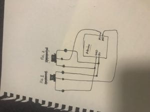
Exercise 1: Sketch using potentiometer to control x and y position of a line.

Arduino code:

// IMA NYU Shanghai

// Interaction Lab

// For receiving multiple values from Arduino to Processing

/*

* Based on the readStringUntil() example by Tom Igoe

* https://processing.org/reference/libraries/serial/Serial_readStringUntil_.html

*/

float posX2 = 0;

float posY2 = 0;

import processing.serial.*;

String myString = null;

Serial myPort;

int PORT_INDEX = 1;

int NUM_OF_VALUES = 2;   /** YOU MUST CHANGE THIS ACCORDING TO YOUR PROJECT **/

int[] sensorValues;      /** this array stores values from Arduino **/

void setup() {

 size(500, 500);

 background(0);

 setupSerial();

}

void draw() {

 updateSerial();

 printArray(sensorValues);

 // use the values like this!

 // sensorValues[0]

 // add your code

 float posX = map(sensorValues[0], 0, 1023, 0, width);

 float posY = map(sensorValues[1], 0, 1023, 0, height);

 stroke(255);

 line(posX, posY, posX2, posY2);

 posX2 = posX;

 posY2 = posY;


}

void setupSerial() {

 printArray(Serial.list());

 myPort = new Serial(this, Serial.list()[ PORT_INDEX ], 9600);

 // WARNING!

 // You will definitely get an error here.

 // Change the PORT_INDEX to 0 and try running it again.

 // And then, check the list of the ports,

 // find the port “/dev/cu.usbmodem—-” or “/dev/tty.usbmodem—-”

 // and replace PORT_INDEX above with the index number of the port.

 myPort.clear();

 myString = myPort.readStringUntil( 10 );  // 10 = ‘\n’ Linefeed in ASCII

 myString = null;

 sensorValues = new int[NUM_OF_VALUES];

}

void updateSerial() {

 while (myPort.available() > 0) {

   myString = myPort.readStringUntil( 10 ); // 10 = ‘\n’  Linefeed in ASCII

   if (myString != null) {

     String[] serialInArray = split(trim(myString), “,”);

     if (serialInArray.length == NUM_OF_VALUES) {

       for (int i=0; i<serialInArray.length; i++) {

         sensorValues[i] = int(serialInArray[i]);

       }

     }

   }

 }

}

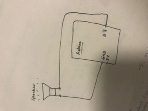
Exercise 2: Musical Instrument

Arduino Code:

#define NUM_OF_VALUES 1    /** YOU MUST CHANGE THIS ACCORDING TO YOUR PROJECT **/

/** DO NOT REMOVE THESE **/

int tempValue = 0;

int valueIndex = 0;

/* This is the array of values storing the data from Processing. */

int values[NUM_OF_VALUES];

void setup() {

 Serial.begin(9600);

 pinMode(7, OUTPUT);

}

void loop() {

 getSerialData();

 // add your code here

 // use elements in the values array

 // values[0]

 // values[1]

//  if (values[0] == ‘H’) {

//    digitalWrite(13, HIGH);

//  } else {

//    digitalWrite(13, LOW);

//  }

 tone(7, values[0]);

}

//recieve serial data from Processing

void getSerialData() {

 if (Serial.available()) {

   char c = Serial.read();

   //switch – case checks the value of the variable in the switch function

   //in this case, the char c, then runs one of the cases that fit the value of the variable

   //for more information, visit the reference page: https://www.arduino.cc/en/Reference/SwitchCase

   switch (c) {

     //if the char c from Processing is a number between 0 and 9

     case ‘0’…’9′:

       //save the value of char c to tempValue

       //but simultaneously rearrange the existing values saved in tempValue

       //for the digits received through char c to remain coherent

       //if this does not make sense and would like to know more, send an email to me!

       tempValue = tempValue * 10 + c – ‘0’;

       break;

     //if the char c from Processing is a comma

     //indicating that the following values of char c is for the next element in the values array

     case ‘,’:

       values[valueIndex] = tempValue;

       //reset tempValue value

       tempValue = 0;

       //increment valuesIndex by 1

       valueIndex++;

       break;

     //if the char c from Processing is character ‘n’

     //which signals that it is the end of data

     case ‘n’:

       //save the tempValue

       //this will b the last element in the values array

       values[valueIndex] = tempValue;

       //reset tempValue and valueIndex values

       //to clear out the values array for the next round of readings from Processing

       tempValue = 0;

       valueIndex = 0;

       break;

     //if the char c from Processing is character ‘e’

     //it is signalling for the Arduino to send Processing the elements saved in the values array

     //this case is triggered and processed by the echoSerialData function in the Processing sketch

     case ‘e’: // to echo

       for (int i = 0; i < NUM_OF_VALUES; i++) {

         Serial.print(values[i]);

         if (i < NUM_OF_VALUES – 1) {

           Serial.print(‘,’);

         }

         else {

           Serial.println();

         }

       }

       break;

   }

 }

Processing Code:

import processing.serial.*;

int NUM_OF_VALUES = 1;  /** YOU MUST CHANGE THIS ACCORDING TO YOUR PROJECT **/

Serial myPort;

String myString;

int PORT_INDEX = 1;

// This is the array of values you might want to send to Arduino.

int values[] = new int[NUM_OF_VALUES];

void setup() {

 size(500, 500);

 background(0);

 printArray(Serial.list());

 myPort = new Serial(this, Serial.list()[ PORT_INDEX ], 9600);

 // check the list of the ports,

 // find the port “/dev/cu.usbmodem—-” or “/dev/tty.usbmodem—-”

 // and replace PORT_INDEX above with the index of the port

 myPort.clear();

 // Throw out the first reading,

 // in case we started reading in the middle of a string from the sender.

 myString = myPort.readStringUntil( 10 );  // 10 = ‘\n’ Linefeed in ASCII

 myString = null;

}

void draw() {

 background(0);

 // changes the values

// for (int i=0; i<values.length; i++) {

//   values[i] = i;  /** Feel free to change this!! **/

// }


 values[0] = mouseX;

 map(values[0], 220, 2000, 0, 100);

// if (mousePressed) {

//   values[0] = ‘H’;

// } else {

//   values[0] = ‘L’;

// }

 // sends the values to Arduino.

 sendSerialData();

 // This causess the communication to become slow and unstable.

 // You might want to comment this out when everything is ready.

 // The parameter 200 is the frequency of echoing.

 // The higher this number, the slower the program will be

 // but the higher this number, the more stable it will be.

 echoSerialData(200);

}

void sendSerialData() {

 String data = “”;

 for (int i=0; i<values.length; i++) {

   data += values[i];

   //if i is less than the index number of the last element in the values array

   if (i < values.length-1) {

     data += “,”; // add splitter character “,” between each values element

   }

   //if it is the last element in the values array

   else {

     data += “n”; // add the end of data character “n”

   }

 }

 //write to Arduino

 myPort.write(data);

}

void echoSerialData(int frequency) {

 //write character ‘e’ at the given frequency

 //to request Arduino to send back the values array

 if (frameCount % frequency == 0) myPort.write(‘e’);

 String incomingBytes = “”;

 while (myPort.available() > 0) {

   //add on all the characters received from the Arduino to the incomingBytes string

   incomingBytes += char(myPort.read());

 }

 //print what Arduino sent back to Processing

 print( incomingBytes );

}
Preparatory Research – Sarah Waxman

Preparatory Research and Analysis

Sarah Waxman

Interaction Lab

18 April 2019

My definition of interaction has run parallel to the skills that have emerged, developed, and evolved throughout this class. It is therefore much more fine-tuned than it was when I first came up with it during the group project, it addresses far more than what my previous interpretations had taken into account. My original definition of interaction took it a step further and added the word “design” in order to be able to narrow it down, because I deemed “interaction” alone to be too broad to be able to exclude any projects at all as required by these projects.

I therefore interpreted interaction to be the direct particular affectation of two or more subjects, events between which there is a period of “processing” — and, in terms of an interactive project and design, at least one such subject must be human (O’Sullivan and Igoe, 2010). Moreover, I took Tom Igoe’s idea into account that “physical computing should ideally foreground the person’s input”, and added that interactive physical computational projects should as well (Igoe, 2008). There must be a change triggered by another change, both perceptible by the system/object/device and viewer or user for interaction to be present, according to my analysis.

I overlooked a crucial element as it simply had not occurred to me to include it as I had made a dangerous assumption that it was implied: time. I have since realized that without explicitly mentioning time, this aforementioned “period of processing” can be any length of time, including infinity which would in real terms render the interaction effectively nonexistent. Consequently, I now add that this processing period must unequivocally range from 0 to any quantifiable, feasible number/length of time that is clearly defined and/or made apparent to the user or viewer. My definition has thereby evolved in a small but essential way.

Thus far, I have decided that for my final project I will create some sort of game with processing, and use a sensor controlled by an Arduino board as I really enjoyed working with sensors this semester. I plan for my project to be partially inspired by Flappy Bird, a mobile game released in 2013 that became immensely popular to such a level that it was ultimately removed from all platforms from which people could once download it in 2014 due to its “life-ruining” addictiveness (Williams, 2014). Despite its simplicity, it can most certainly be considered an interactive project as it translates a physical touch to the screen to a movement of the bird immediately (ideally).

On the other hand, an example of a very complex and technologically advanced project that does not fit into my idea of an interactive project is “CAVE”, a Virtual Reality film experience that allows the viewer to be in the virtual movie set along with other members of the audience (CAVE, 2018). While not an interactive design, it is definitely a fully immersive experience created by Academy Award winner and NYU professor Ken Perlin. In order to make it fulfill the criteria of an interactive design project, the film would need to include some sort of mechanism that gives a limited amount of control over the experience, that gives some sort of choice or movement-response between the scene/character holograms and the audience.

As a result, my “new” definition of interaction is as follows: a perceptible change that is a result or response to a person’s (spectator or user) input which therefore effectively gives the person a certain amount of control, and it must occur within a measurable and previously defined period of time. This enumeration of time may be present in the code, program, or construction behind the interactive system.

Works Cited:

CAVE, Tribeca Film Festival, Virtual Reality Lab, 2018, www.tribecafilm.com/filmguide/cave-2019.

Igoe, Tom. “Physical Computing’s Greatest Hits (and Misses).” Code Circuits Construction, TIGOE, 27 July 2008, www.tigoe.com/blog/category/physicalcomputing/176/.

O’Sullivan, Dan, and Tom Igoe. Physical Computing: Sensing and Controlling the Physical World with Computers. Course Technology, 2010.

Williams, Rhiannon. “What Is Flappy Bird? The Game Taking the App Store by Storm.” The Telegraph, Telegraph Media Group, 29 Jan. 2014, www.telegraph.co.uk/technology/news/10604366/What-is-Flappy-Bird-The-game-taking-the-App-Store-by-storm.html.

Recitation 7, Processing part 2 – Sarah Waxman

For the in class exercise, I decided to create a flower.

One of the most interesting functions I used was rotate(), as this is what allowed for the animation in addition to translate() which allowed me to set the center point to be wherever the cursor’s position is. The for() function facilitated the simplification and efficiency of the code so that I would not have to repeat the petals shapes 9 separate times to create 9 petals. I remembered I could do this only after I had already drawn three petals 3 separate times, so at least I was able to save the time it would have taken to draw the other 6 (subtracting, of course, the time it took for me to write the for() function).

Here is the code:

void setup() {

size(600, 600);

smooth();

frameRate(60);

noStroke();

}

void draw() {

background(200,200,2000);

smooth();

// set center point

translate(mouseX, mouseY);

//make the flower rotate with frameCount

rotate(radians(frameCount + mouseY + mouseX));

// draw 9 petals, rotating after each one

fill(2000,200,2000);

for (int i = 0; i < 9; i++) {

 ellipse(0, -50, 25, 100);

 rotate(radians(40));

}

// center circle

fill(198,255,137);

ellipse(0, 0, 55, 55);

}

For the homework exercise, I followed the instructions to create a centered circle that grows and shrinks continuously while its color changes as well simultaneously. The animation includes the arrow keys which, when pressed, will move the circle around the screen/canvas. Finally, I added the edges of the screen/canvas as the borders so that the circle could not totally disappear from moving it too far with the arrow keys. Using color mode HSB was something I had not previously done and was very fun and entertaining to learn, as we have not focused much on the ways we could create different colors and color combinations in class or in recitation. I found the keyPressed() function to be quite challenging at first as well as setting the borders but once I was shown how to do the first one with the help of a classmate, I was able to write the rest more fluidly.

The homework exercise code:

int circleX;

int circleY;

int radius;

int circle

Speed;

int growSpeed;

float c;

float size = 300;//create a variable in order to be able to change the value of something

boolean pulse = false; //create a boolean variable in order to define the state of increase/decrease

void setup() {

size(600, 600);

colorMode(HSB); //set the color mode to HSB, so that the scope of float variable c is between 0 and 255

smooth();

frameRate(60);//set frameRate to 60 so that the code runs smoothly and at that speed

circleX = width/2;

circleY = height/2;

radius = 25;

circleSpeed = 10;

growSpeed = 4;

}

void draw() {

background(255);

if (c >= 255) {

c=0;

} else {

c++;

}

//change the color

strokeWeight(25);

noFill();

stroke(c, 255, 255);

ellipse(circleX, circleY, radius*2, radius*2);

//circle size gets bigger and smaller in a loop

radius = radius + growSpeed;

if(radius > 150) {

growSpeed = -3;

}

if(radius < 5) {

growSpeed = 3;

}

}

//move the circle by pressing on any of the arrow keys

void keyPressed() {

if ( (keyCode == LEFT) && (circleX > radius*2) ) //set the condition that pressing on the left arrow key and that the x coordinate of the circle has to be greater than the radius

{

circleX = circleX – circleSpeed;

}

if ( (keyCode == RIGHT) && (circleX < width-radius*2) )

{

circleX = circleX + circleSpeed;

}

if ( (keyCode == UP) && (circleY > radius*2) )

{

circleY = circleY – circleSpeed;

}

if ( (keyCode == DOWN) && (circleY < height-radius*2) )

{

circleY = circleY + circleSpeed;

}

}

Midterm Project Documentation – Sarah Waxman

INTERACTION LAB

SPRING 19


“ChaCool” – Sarah Waxman – Young Chung

INDIVIDUAL REFLECTION:

My previous research exposed me to a variety of different forms of interaction, especially within the context of interactive design. Out of the many projects I encountered during my research, the one that resonated with me the most was Daniel Rozin’s PomPom Mirror, a project that truly clicked in my mind as the ultimate form of interaction design. It was through this project that I was able to narrow down the definition of interaction, by narrowing the term down to “interaction design.” This was due to the fact that the word “interaction” alone was too broad for me to be able to exclude any projects from fitting into the criteria. Ultimately, I defined it as the direct particular affectation of two or more subjects, events between which there is a period of “processing” — and, in terms of an interactive project, at least one such subject must be human (O’Sullivan and Igoe, 2010). Furthermore, I would agree with Tom Igoe in that “physical computing should ideally foreground the person’s input”, as should interactive physical computational projects (Igoe, 2008). A valuable lesson I learned from this midterm project, however, is the importance of the output’s timely manner. The practically immediate and tangible response from PomPom Mirror to the viewer triggered my understanding, as well as the way it forced the human to be a part of the project; the human and thereby the interaction was a necessary component for the system to exist as intended.

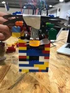
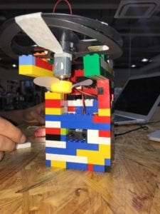
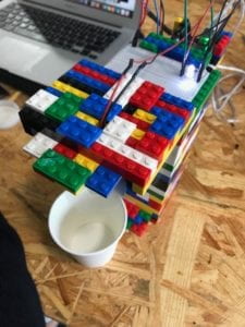
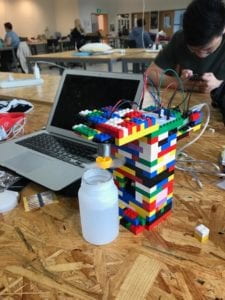
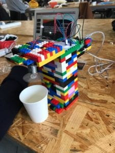
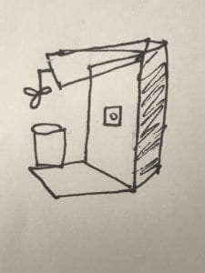
One summer that my partner, Santiago visited a hospital (Hospital Simon Bolivar) in Colombia, he noticed that the burn victims were struggling to blow into their hot drinks in order to cool them. He empathized with them and in light of his experience, we wondered what kind of product we would like to see readily available to them. The purpose of our project is therefore to provide a fun and interactive solution for children who suffer from the long term effects of severe burns as well as from facial paralysis. We created a machine that would apply air to the top of a cup filled with a hot drink in a way that would not any more than placing it in a certain place, as one would place a cup under their mouths to blow on it. The colorful LEGO design and structure is deliberate. We aim to attract children to this device, so that they enjoy using it rather than feeling like it is purely a necessity. This design also contributed to its our project’s originality. Another motive was to take the concepts and skills we had learned in class, such as the programming that would link a sensor’s detections to a potentiometer and/or LED, and design something meaningful with them. Ultimately, we took these skills to program a distance sensor and link it to a fan blade as well as an LED, which would both act based on the sensor. We were aware that our target users generally have perfect use of their hands and arms, so this would work well for them. At one point, we considered adding a base to the bottom of the machine where the user’s hot beverage cup would go, then decided against this due to the variability of the sizes of cups. We did not want to restrict the type or size of cup, a reason for which we also ended up rejecting the idea of a heat sensor which would have required a metal cup (or another quick heat-transferring material). Another reason we rejected this is because while it sounded great during our user testing – which is where the idea came up – we thought more about it and realized, through common sense, that a person could simply touch the cup and determine whether it is at the temperature they are satisfied with. Even simply trying the beverage would work, as that is what is normally done after one blows into their cup, and, after all, the idea of the machine’s functionality (excluding the aesthetic qualities) is simply to offer an alternative to blowing. Another decision we made was rejecting a laser cut or 3D printed structure for our design. Both would have limited us to their materials and available colors, which are not many and could not be made multi-colored during our time frame. Therefore we elected the LEGOs, as they fit into our criteria of colorful and cheery material that is relevant to children as well, and that gave us the flexibility to improve and tweak our design more often and effectively to allow us to eventually perfect it. Structurally, we also added a sort of “shelf” for the breadboard as well as for the Arduino towards the top and back, in a way that would make sense to connect the wires. 

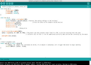
Many challenges were encountered and addressed before and after the user testing session. When we built the original structure and tested it ourselves for the first time, we realized the placement the fan resulted in the blades making contact with some LEGOs, preventing it from working properly. We then deconstructed and reconstructed the top of our structure too many times to count, until this issue was resolved. During the user testing, someone accidentally pulled on the cable connecting our project to its power source and half of it collapsed. We then understood we must either change our material or reconstruct it to be more of a firm structure, and decided to use portable power (i.e. batteries) in order to avoid a repeat of this type of mishap. Since received a substantial amount of positive feedback on our use of LEGOs during the user testing, we chose to keep the latter option. Briefly before the user testing session began, we had also added some short written instructions on the machine. Nevertheless, as we wordlessly watched people use our product correctly, we noticed that they were not even looking at the instructions and we consequently decided to remove them for the final product – we found something we could simplify in terms of user experience. The final steps were to further strengthen it, make it taller and cleaner, and generally polish it. A major challenge we came across was a delay in the response of the fan to the sensor’s detection of a nearby object. At first we thought it might be due to the fan blade, so we changed it to a different one and the problem persisted. We then realized it might be in the code, so we changed the distance at which the sensor would cause the motor (fan) to rotate from 16cm to 10cm, and later from 10cm to 5cm. The project then worked perfectly – that is, until the final presentation of our project during which this issue unfortunately reared its head once more. The advice we received then was exactly what we had done earlier: to adjust the distance in the code for the distance sensor. Perhaps, given more time, we could have figured out the core issue which undoubtedly went beyond the code.

Once again, the goal of our project was to offer an alternative to children who do not have the ability or have lost the ability to blow air out of their mouths as easily as most can, all while incorporating the skills and lessons learned in class and during various recitations. The final product aligns with my aforementioned definition of interaction design, as it requires a human input (placing a cup under the fan and in front of the sensor) to deliver a particular and simultaneous response of the fan spinning and blowing air into the cup. Nevertheless, due to the fact that the sensor will detect more than just cups filled with hot beverages placed their specifically by a human and the fan will work nonetheless, the product in that case does not fit into my definition of interaction design. In the end, the audience interacted with our project as expected – even their smiles fit into our further purpose for it to have a cheerful aesthetic quality. If we had had more time, as previously stated, we may have been able to reach the root of the delay issue which only sporadically came up. Moreover, given more time (and LEGOs) we could have cleaned it up a bit more and hidden the electrical components better within a larger structure, for which we would have also needed the time to obtain more LEGOs. Another aspect we might have changed would have been the planning and organization of the LEGOs, to perhaps stack them in a particular way that would create a cheery shape such as a smiley face. Our primary setback during this project was a mental barrier in the sense that, as both my partner and I had no previous background in circuits, programming, or design, we felt at a disadvantage. By the end of this project I learned that this was an artificial setback as we were able to accomplish something that a few months earlier I could not have even imagined myself doing. Furthermore, I learned that there is no such thing as failure if one sees it only as an extra step to success: all the challenges we encountered we managed by being flexible with our design and idea. I therefore learned the value of not marrying the original idea and constructive feedback can be very helpful, as long as one is resilient and flexible.

Works Cited:

Daniel Rozin, Daniel Rozin, PomPom Mirror, 2015 from Bitforms Gallery on Vimeo, 4 Jan. 2016, www.youtube.com/watch?time_continue=2&v=yIx8RODt6F8.

Igoe, Tom. “Physical Computing’s Greatest Hits (and Misses).” Code Circuits Construction, TIGOE, 27 July 2008, www.tigoe.com/blog/category/physicalcomputing/176/.

O’Sullivan, Dan, and Tom Igoe. Physical Computing: Sensing and Controlling the Physical World with Computers. Course Technology, 2010.

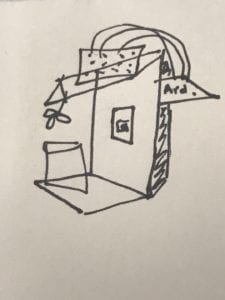
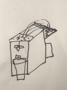
Some images showing our progress/process:

Recitation: Processing – Sarah Waxman

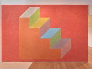
Sol Lewitt

The image above is the one I chose as a motif, mainly because I liked the 3D effect Lewitt created through the shape placement and colors.

I encountered some trouble when trying to figure out how to use colors beyond blue, red, and green. I resolved this issue by tweaking the numbers until I noticed a pattern in the changes. Moreover, I was very confused at first in terms of the x and y coordinates — I was mistakenly operating under the assumption that the y-axis was going from bottom to top, when it really goes from top to bottom. I soon understood once I researched using the Processing website.

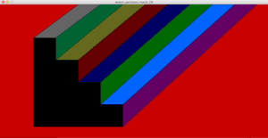
Once I was able to figure out how to create new colors, I decided to divert from the motif I was originally following as I wanted to further experiment. I also changed the central design a bit as I made the “steps” (horizontally) stretch to the edge of the screen because I wanted to create the visual effect of them going on eternally, and I aimed to add an aspect of originality. I think processing is a good medium through which to create shapes with exact measurements, such as perfect circles and, in this case, exactly equal spacing between shapes. 

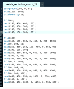
Below is the final image as well as the code.