Final Preparatory Research by Shina Chang

My first definition of interaction displayed my very basic knowledge about the subject. I interpreted “interaction” as a conversation between two people or two robots. Interaction to me now is when two or more subjects converse in the way that they react to the actions of each other, but then the conversation should dive further and further into a more intricate form of action and reaction. For example, the interaction between a video game and the player, as the player gets better at reacting to what to the video game is displaying the required amount of interaction increases as the levels get harder and harder. However, if the video game did not increase in difficulty then the level of interaction would be stagnant because there would be no need to improve as a player. This definition of interaction is different from what my midterm project displayed. My midterm project did not require the user to become better at using it but it rather was just a device to make exercising more comfortable. There was a lack of developing interaction between my midterm projects user and the project itself.

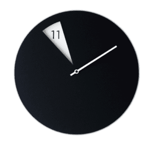
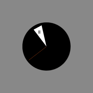
A project that I think resembled my midterm project is a project called The Weekly Agenda. This is an interactive weekly planner that allows the user to make planning a little bit more fun. The level of interaction is more intricate than my midterm project because the planner can do more than one thing like the interactive sports gear but the level of interaction comes to a halt once the user is familiar with how to use the planner and all of its qualities. I want to avoid the situation where only a couple of interactions between user and subject is enough for the user to lose interest or master how to use it. With my final project, I hope to maintain and develop the level of interaction between the project and the user.

A project that displays my new definition of interaction is Dance Dance Revolution by Konami. This game requires full body engagement with the game, and for every action, the user performs the game reacts such as the next move or even a higher level of difficulty. The user must “dance”, just step on the corresponding directional arrow, to stay engaged in the game.  This interactive game utilizes sensors to read applied pressure, in my final project I would like to include sensors to detect the user’s physical activity. Also, the game is constantly evolving with the music industry so this game basically has no expiration date. I would like to create a final project that could be used timelessly and easily.

I think that interaction is a fluid form of communication between two or more subjects and where every action results in a reaction. Then, as communication continues the transferral of information becomes more intricate keeping the conversation interesting. Konami created an interactive game that involves the user to physically move in order to keep the game playing making the interaction between user and game fluid. Also, the game provides multiple levels as well as multiple songs to dance to which keeps it interesting. The Weekly Agenda though is simplistic enough in its design that anyone can use it.

Recitation 7 Documentation (Shina Chang)

Recitation Exercise:

This week in recitation we had to animate something using functions we learned in processing. We had to make an animation where the display is showing the subject moving around the screen. I decided to use what we learned in class recently and incorporate functions we had to use during recitation. I created an animation where if you press the ‘s’ then the screen will go from a red frowning face to many purple vibrating smiley faces with one smiley face following the mouse around the screen. 

code:

PFont p;
int amount = 255;
int[] xpos = new int[amount];
int[] ypos = new int[amount];
int[] sizes = new int[amount];

void setup() {
size(600, 600);
background(255);

p = createFont(“Arial”, 28, true);
for(int i=0; i<amount; i++) {
sizes[i] =int(random(20, 50));
xpos[i] = int(random(width));
ypos[i] = int(random(height));
}

}

void draw() {
background(255);

textFont(p);
fill(0);
textAlign(CENTER);
text(“Press S”, width/2, 550);
if(keyPressed) {
if(key == ‘s’){
for(int i=0; i<amount; i++) {
drawFace(sizes[i], xpos[i], ypos[i], #6A0D93);
xpos[i] += random(-5,6);
ypos[i] += random(-5,6);
drawFace(pmouseX, pmouseY, mouseX, mouseY);
}
}
}else{
fill(#CE0C0C);
ellipse(300, 300, 350, 350);
fill(0);
ellipse(230, 260, 50, 50);
ellipse(370, 260, 50, 50);
fill(0);
arc(300, 400, 240, 150, 3.14, 6.28);

}
}

void drawFace(int size, float x, float y, color c) {
noStroke();
fill(#6A0D93);
ellipse(x, y, size, size);
fill(255);
ellipse(x-size*0.3, y-size*0.1, size*0.05, size*0.05);
ellipse(x+size*0.3, y-size*0.1, size*0.05, size*0.05);
arc(x, y, size*0.6, size*0.6, 0, PI);
}

Homework:

For homework we had to create a expanding and contrasting circle that can be moved around the screen using the keyboard arrow keys. 

code:

int x = 300;
int y = 300;
int size = 10;
int add = 10;
int c;
int change = 1;

void setup() {
size(600, 600);
}

void draw() {
background(255);
noFill();
stroke(random(255),random(255), random(255));
strokeWeight(15);
ellipse(x, y, size, size);
size = size+ add;
if(size>width ||size<10) {
add *= -1;
}
}
void keyPressed() {

if (key == CODED){
if (keyCode == UP){
y = y-10;

}else if (keyCode == DOWN){
y = y+10;

}else if (keyCode == LEFT){
x = x-10;

}else if (keyCode == RIGHT){
x = x+10;

}else {
x = 300;
y = 300;
}
}
}

I was unable to utilize the colorMode() function because it just made my background a solid color so I replaced it with the stroke() function and inserted the random() function. 

Reflection:

The most interesting functions I have used thus far have been the random() function and making an object follow the cursor using mouseX and mouseY positions. The most difficult aspect of using processing is figuring out how to translate what I want the computer to do and figuring out which sets of code will get the computer to do what I want it to do. I am getting more comfortable with the different functions and what they can do for my code. 

Recitation 6: Processing Basics by Shina Chang

I chose this image of a simple and minimalistic clock because it utilizes multiple shapes at different angles, which I thought would be challenging, but the fun photo to recreate in Processing.  In Processing I wanted to recreate this photo exactly and I managed to do so with some deviants.

This is the clock I recreated but with a little colorful twist. I managed to draw the black filled circle and place it in the center of the page using a color function, stroke, fill and creating an even ellipse. Then I create the triangle, and I had the most difficulty with it because using the triangle function I had to manipulate the individual values to see which value affected what part of the triangle. Eventually, I was able to create an acute, upside down triangle that displayed the hour. My next challenge was to label the hour triangle. To create the eleven I used the rectangle function and manipulated the values to draw very small rectangles in the shape of the number one. Again I had the same struggle as the triangle function, figuring out which values changed a specific vertex on the rectangle took many trials. When I had to draw the minute hand of the clock I had learned how to use the functions, so I just used the line function to draw the hand. Although I do like the minimalistic view of the original clock design I do like a pop of contrasting colors and I think the rusty minute hand does a fair job of giving the user a subtle change of scenery in a pleasant way. I made the line thin enough to not distract from the minimalistic color scheme but still large enough to see, and the length of the hand makes it easy to read and estimate what the exact time is.

Code:

size(600,600);

background(136);

fill(0);

fill(255);

color c = color(0);

stroke(0);

fill(c);

ellipse(300, 300, 300, 300);

color t = color(255);

noStroke();

fill(t);

triangle(220, 195, 270, 168, 300, 300);

color n = color(0);

noStroke();

fill(n);

rect(251, 200, 3, 20);

rect(258, 200, 3, 20);

//rect(x-axis, y-axis, width, height);

stroke(#FA5508);

line(300, 300, 390, 385);

Chill Out- Shina Chang- Professor Eric Parren

For our project, my partner and I struggled with coming up with a struggle we both encounter enough to seek a solution for, so we turned to resolve a problem most other people face, sweating uncontrollably while working out. We thought it was amusing we would try to do such a thing but thinking about it we realized that we could build our activewear to do what we would want our activewear to do. So we decided on creating a headband that would hold hair back, absorb sweat, and give us the option to fan ourselves, if needed, and paired it with an armband that has space to securely hold a phone. The special aspect of our headband was that it incorporates the use of a temperature sensor within the headband to monitor body heat and activate fan usage. If the user reaches a high enough temperature then they could use the fan as they please but if they do not reach the needed temperature then the fan would not turn on at the push of the button. We used a temperature sensor instead of a moisture sensor because not everyone sweats so our activewear is good for anyone who works out and wants to stay cool while looking cool.

It was suggested during the user testing that we combined the temperature sensor portion of the setup with the breadboard and Arduino and form it into a sort of hat instead of a headband, but due to time constraints we were not able to test out the suggestion but I think that that extra weight on the head is a nuisance when working out so specifically for this project I do not think that a weighted hat would feel great but it might have been more aesthetically pleasing. During user testing, we were asked why would we incorporate a temperature sensor into activewear, wouldn’t the user know whether or not if they are hot and can turn on a fan themselves. I think yes a user could just turn on a fan if they were feeling warm but I think our design gives the user more control over their fan because it interacts with their body and provides access to the fan when it senses that you need it the most. This way if the user is to wear the headband as part of their athleisure outfit they cannot be distracted by the attached fan, whereas and small portable fan could be a fun toy when procrastinating.

Our original circuit not working after cosmetic modifications

Our final design consists of a matching set of a headband and armband. It is made of a soft, gray fabric that is handsewn which ensures proper and comfortable placement of the wires throughout the headband and armband. The headband has the temperature sensor neatly tucked away in the fabric so that it laid comfortably on the user’s temple and then through one of the long strands that hangs down the fan was safe inside the fabric. The placement of the fan, along with its button, is conveniently put to hang down the user’s front side so that it is easy to reach. We made the armband adjustable by using a 3D printed clip using files from thingiverse.com. My partner and I encountered a huge problem with printing the clip and ended up attempting to print the female half of the clip for than 8 times and only with the help of a fellow and a different file clip from the original version did we print a decent female clip. Each clip seemed to be printing too thin and broke as soon as we clipped the two pieces together. We were told that our set is comfortable to wear but may be a little too thick and may promote sweating rather than preventing it. In the future, if we were to update this project we will most likely change the fabric material and try to make the wires more hidden someway.

A huge problem we ran into was the code. It worked well at first and was very long and complicated as we tried to combine the motor fan set up and a temperature sensor set up we learned in class. This worked at first but then stopped working when we started trying to fit it into the fabric. we solved this by completely redoing the code to the one shown below with the help of a fellow. 

First working circuit

Ultimately, my partner and I achieved the activewear we were attempting to create. The headband only works through interaction with it and we received fairly positive constructive criticism. Users understood our concept, was a little confused with our execution during user testing but interacted with it properly. Without too much explanation, users understood that it consisted of a headband and an armband, but the wires made how to put it on a little confusing. In the future, we would attempt to make this device wireless to reduce confusion and give the user more freedom to move and decide how to wear it. This project has taught me that 3D printers are really finicky and will work sometimes. User testing is really important for projects like these because it helps you weed out flaws you might have overlooked. For example, as the creator, I know what I am building or creating so when a user cannot tell how to interact with what I made makes me realize that I have to simplify and modify it so it is easier to digest.

Code:

int pushButton = 2;

// give a name to digital pin 2, which has a pushbutton attached

int motorControl = 9;

// the transistor which controls the motor will be attached to digital pin 9

int tempPin = A0;

// sets the pin for the temp sensor

//int ledPin = 13;

boolean oldSwitchState = LOW;

boolean newSwitchState1 = LOW;

boolean newSwitchState2 = LOW;

boolean newSwitchState3 = LOW;

boolean LEDstatus = LOW;

void setup() {

 pinMode(pushButton, INPUT);

 // make the pushbutton’s pin an input

 pinMode(motorControl, OUTPUT);

 // make the transistor’s pin an output

 pinMode(tempPin, INPUT);

 //make the temp sensor an input

 //pinMode(ledPin, OUTPUT);

 digitalWrite(motorControl, 0);

 Serial.begin(9600);


}

void loop() {

 int temp = analogRead(tempPin);

 newSwitchState1 = digitalRead(pushButton);

//  delay(1);

// newSwitchState2 = digitalRead(pushButton);

// delay(1);

// newSwitchState3 = digitalRead(pushButton);

 Serial.println(newSwitchState1);

 //if(temp >= 45){

 if (newSwitchState1 == 1) {

    analogWrite(motorControl, 0);

    Serial.println(“motor on”);

   // pass currenr through fan


   } else {

      analogWrite(motorControl, 255);

       Serial.println(“motor off”);

     }

 }

Citations:

Female clip:

https://www.thingiverse.com/thing:3415522

Male clip:

https://www.thingiverse.com/thing:2591485

Recitation 4: Drawing with a Stepper Motor by Shina Chang

What we used: 

  • Pen
  • Paper
  • Five Paper Fasteners
  • An Arduino kit and its contents
  • A stepper motor
  • A 12 VDC power supply
  • An ic chip
  • A power jack
  • Two of each Laser-cut short and long arms
  • Two Laser-cut motor holder
  • Two 3D printed motor

Step 1:

I thought this step was the most tedious as we had to use an H-Bridge which is small and had many legs that all needed to be connected to something. There was also a risk of breaking the Arduino and possibly my computer if connected incorrectly which added to this steps difficulty.

Given Stepper Motor Schematic

Following this schematic, I set up the circuit and had it working flawlessly with the given code. I had a fellow double check to prevent any possible damage.

Stepper Motor Set Up

Step 2:

Given Potentiometer Schematic

This step was much easier than step one because it used relatively the same circuit set up with a potentiometer added to it.  I had the stepper motor working with the potentiometer added to it but I did not have them working together. Even if I was twisting the potentiometer it did nothing to the motion of the stepper motor. This was because my code was incorrect and I forgot to add the mapping function to the code so the ranges of the stepper motor and the potentiometer were not converted. I had forgotten to add Map(potentiometervalue, 0, 1023, 0, 200) and the 200 value was used instead of the usual 255 because it was a 200 step stepper motor. After the changes, the motor and the potentiometer worked as intended.

Drawing With Machine

Step 3:

This step was the easiest and the most fun. Once my partner and I’s potentiometer and stepper circuits were working we placed the needed parts onto the stepper motor and used the potentiometer to control the arms. There were no problems in doing so and our setup ended up accidentally drawing a sad face.

Our Drawing

Question 1:

I would love to build a piece of machinery that would help me in putting clothes away as soon as I take them off after a long day in them. I always seem to have a section of my room designated to just a pile of worn-but-could-be-worn-again clothes that I didn’t want to put into my closet of clean clothes. I want to design a drawer that would fold my clothes for me and organize it by how often I wear it so that I could do the bare minimum of putting the piece of clothing into the correct drawer. This invention would eliminate worry about the drawer not shutting properly because I didn’t fold the clothes in it right or pulling out a sweater and two shirts when grabbing a pair of jeans. An actuator would be used for the piece of machinery that is responsible for folding the clothes and placing them accordingly.

Question 2:

Waves by Daniel Palacios Jiménez is an interesting piece that uses motors to create art. I think this is similar to what we created during recitation because we also used motors to create art with a pen attached to it. However, the art we created is more complex because we could draw more with small movements of the potentiometer and we had infinite combinations we could do with the two motors. In Jiménez’s creation, the motors he chose moved in a continuous vertical motion to create waves that resemble a sin graph, but if he were to move the motors in any way it could disturb the sin waves which could result in no waves at all.