Individual Reflection
This project was not entirely inspired by the Group Project, but the original reason for both was the same. For the group project, the original reason for creating the Life Saver was solving a problem many people face, swimming. In the case of the Pianote, the problem being solved was that many people walk up to a piano and say, “I wish I could play piano”. This project was similar to traditional player pianos but tried to get the user actually involved instead of just letting the piano play itself. In the case of the player pianos, I do not think this was an example of interaction because they only reacted to the user turning them on. In addition, a few weeks before the project began, I went to the World Music Expo and saw them attaching screens to pianos to teach children how to play the piano without having a teacher. The problem I saw with the set up of the piano I saw was that the screen assumed you already knew how to read music, and not many people can. In our take of this kind of situation, we wanted the piano to be more like a teacher and not like a screen that you looked at.
I wanted users to feel like they were playing a real piano, so I wanted to make sure that the keys stood out on the box. In addition, after the User Testing session, we switched our box to be more focused on the piano keys themselves because many thought the brown was an out of place color for a piano. We used the element of color to emphasize these keys and show the contrast as the keys were white and the box was white. We originally were using a normal cardboard box but changed it to a laser-cut box instead because it had cleaner lines compared to the flimsy cardboard box. In addition, we decided to add 2 modes to the piano because we knew some people already knew how to play the piano (found in the User Test), so we made a free play mode that allowed those with previous experience the ability to play.
For the keys, we used 3D designing to make them and print them. The first time when we printed it, the keys would not split apart, so we had to re-edit it so they would come apart as separate keys. In addition, the 3D printers only have one filament, so we had to print 2 copies of the piano file. The first set, the all-black keys went off without a hitch. The white keys were a very different story. We had a very hard time working with first the white filament, so we changed it to white PLA and then the printer kept having trouble heating the plate to keep the keys attached to the platform. To solve this problem, we switched to the printers in the fabrication lab to print the keys. On the day of the User Testing Session, we got many comments about the aesthetic of our box, so we laser-cut a new one and spray-painted it black.
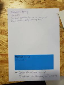 User Test notes
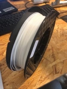 new filament
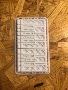 printer issue
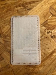 plate heating issue
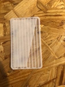 plate heating issue
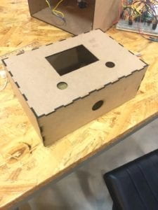 new box
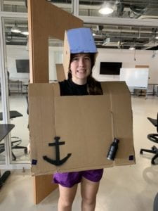
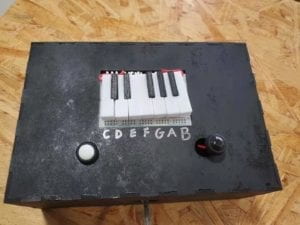 Top of final project
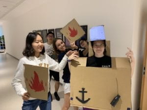
 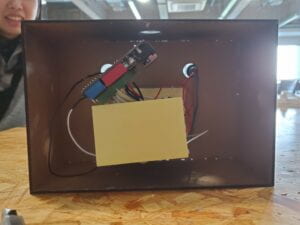 Inside of final project
CONCLUSIONS:
The original goal of the project was to teach someone how to play Twinkle Twinkle on the piano. I think my project aligns with my definition of interaction because it was able to get the user to give input and have the project take that input return output and also give an input for the user. I think the free play mode does not align with my definition of interaction because the project is only reacting to the pressing of the buttons. With more time, I would have made the switch between modes universal, as you could only switch from free play to learning mode and not the other way around. I think making sure you have enough time for the preparation of final prototyping is needed for next time. I think this project was important because many times no one has the time to pick up a new skill and this project eliminated this issue by teaching Twinkle Twinkle without even needing to read sheet music, nevermind hours of practice.
CODE:
int speakerPin = 10;
int C = 3;
int D = 4;
int E = 5;
int F = 6;
int G = 7;
int A = 8;
int B = 9;
#define white 11
#define black 12
bool menu = true;
bool freePlay = false;
bool twinkle = false;
#include "pitches.h"

// notes in the melody:
int melody[] = {
  NOTE_C4, NOTE_C4, NOTE_G4, NOTE_G4, NOTE_A4, NOTE_A4, NOTE_G4, NOTE_F4, NOTE_F4, NOTE_E4, NOTE_E4, NOTE_D4, NOTE_D4, NOTE_C4, NOTE_G4, NOTE_G4, NOTE_F4, NOTE_F4, NOTE_E4, NOTE_E4, NOTE_D4, NOTE_G4, NOTE_G4, NOTE_F4, NOTE_F4, NOTE_E4, NOTE_E4, NOTE_D4, NOTE_C4, NOTE_C4, NOTE_G4, NOTE_G4, NOTE_A4, NOTE_A4, NOTE_G4, NOTE_F4, NOTE_F4, NOTE_E4, NOTE_E4, NOTE_D4, NOTE_D4, NOTE_C4
};

// note durations: 4 = quarter note, 8 = eighth note, etc.:
int noteDurations[] = {
  4, 4, 4, 4, 4, 4, 2, 4, 4, 4, 4, 4, 4, 2, 4, 4, 4, 4, 4, 4, 2, 4, 4, 4, 4, 4, 4, 2, 4, 4, 4, 4, 4, 4, 2, 4, 4, 4, 4, 4, 4, 2
};

void setup() {
  Serial.begin(9600);

  // iterate over the notes of the melody:
  for (int thisNote = 0; thisNote < 42; thisNote++) {

    // to calculate the note duration, take one second divided by the note type.
    //e.g. quarter note = 1000 / 4, eighth note = 1000/8, etc.
    int noteDuration = 1000 / noteDurations[thisNote];
    tone(10, melody[thisNote], noteDuration);

    // to distinguish the notes, set a minimum time between them.
    // the note's duration + 30% seems to work well:
    int pauseBetweenNotes = noteDuration * 1.30;
    delay(pauseBetweenNotes);
    // stop the tone playing:
    noTone(10);
  }
  pinMode(speakerPin, OUTPUT);
  pinMode(C, INPUT);
  pinMode(D, INPUT);
  pinMode(E, INPUT);
  pinMode(F, INPUT);
  pinMode(G, INPUT);
  pinMode(A, INPUT);
  pinMode(B, INPUT);
  pinMode(white, INPUT);
  pinMode(black, INPUT);
  Serial.println("Welcome to Pianote, where you learn to become Beethoven!");
  delay(1000);
  Serial.println("Which mode would you like to play in?");
    delay(1000);
    Serial.println("If you would like to free play, press the white button");
    Serial.println("If you would like to learn how to play a song, press the black button");
}

void loop() {
  // no need to repeat the melody.
  if (menu == true) {
    //Serial.println("If you would like to free play, press the white button");
    //Serial.println("If you would like to learn how to play a song, press the black button");


    if (buttonPressed(white) != false)
    {
      Serial.println("Alright, let's head to free play!");
      menu = false;
      freePlay = true;
      Serial.println("Welcome to free play");
      Serial.println("This is a C major keyboard, so we will only use the white keys");
    }


    if (buttonPressed(black) != false)
    {
      Serial.println("Alright, let's learn a song!");
      menu = false;
      twinkle = true;
      Serial.println("Today, we're going to learn how to play Twinkle Twinkle");
    }
    //delay(10000);
  }
  if (freePlay == true)
  {

    if (buttonPressed(C))
    {
       tone(speakerPin, NOTE_C4, 1000);
       delay(1000);
    }
    if (buttonPressed(D))
    {
       tone(speakerPin, NOTE_D4, 1000);
       delay(1000);
    }
    if (buttonPressed(E))
    {
       tone(speakerPin, NOTE_E4, 1000);
       delay(1000);
    }
    if (buttonPressed(F))
    {
       tone(speakerPin, NOTE_F4, 1000);
       delay(1000);
    }
    if (buttonPressed(G))
    {
       tone(speakerPin, NOTE_G4, 1000);
       delay(1000);
    }
    if (buttonPressed(A))
    {
       tone(speakerPin, NOTE_A4, 1000);
       delay(1000);
    }
    if (buttonPressed(B))
    {
       tone(speakerPin, NOTE_B4, 1000);
       delay(1000);
    }
  }
  if (twinkle == true)
  {
    Serial.println("We're going to learn how to use Twinkle Twinkle in C major, so we will only need the white keys");
    Serial.println("The first note of Twinkle Twinkle is C");
    tone(speakerPin, NOTE_C4, 1000);
    Serial.println("C is the first key on the left. Press it.");
    if (buttonPressed(C))
    {
      tone(speakerPin, NOTE_C4, 1000);
      Serial.println("Good job!");
    }
    else
    {
      if (buttonPressed(C) == false)
      {
        Serial.println("Sorry, not that one, the white key all the way to the left!");
      }
    }
  }
}

//Checking if button is pressed
int buttonPressed(uint8_t button)
{
  static uint16_t lastStates = 0;
  uint8_t state = digitalRead(button);
  if (state != ((lastStates >> button) & 1))
  {
    lastStates ^= 1 << button;
    return state == HIGH;
  }
  return false;
}