Materials
Arduino Uno: The processor to answer our code
Breadboard: the board we can build circuits on it.
Buzzer: play music when it receives electric signal and serves as the output.
LEDs: give light when it is powered on and serves as the output..
220-ohm resistors: add resistance to the circuit to protect the circuits.
10K-ohm resistors: add resistance to the circuit to protect the circuits.
pushbuttons: works as a switch to allow us control the circuits.
arcade buttons: add resistance to the circuit to protect the circuits.
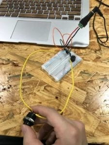
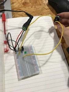
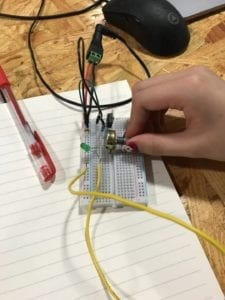
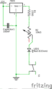
Circuits
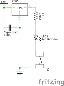
Circuit 1: Fade
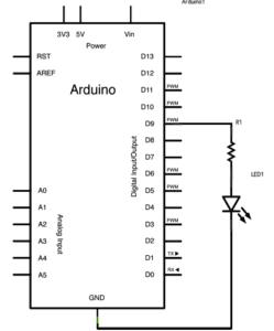
diagram found here
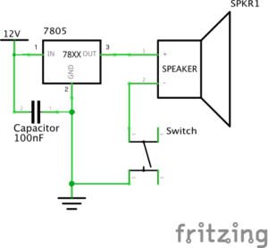
Circuit 2: Tone Melody
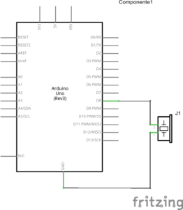
diagram found here
Circuit 3: Speed Game
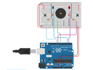
diagram found here
Circuit 4: 4 Players Speed Game
Processes
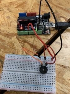
The first two circuits were very easy so my partner and me finished them quickly. The third one was a little bit complex and we used some time to finish it. The problem we met in the first three was some time we did not connect the wires to breadboard tightly. Thus, even if our circuits are somehow right, it could not work. We cooperated with another group to build circuit4 and we needed to connect our two breadboards together onto our Arduino Uno. I was responsible to writing code for Arduino Uno. I found that the programming language was very different from Python. For example, I always forgot to put a “;” at the end of each sentences. And I did not understand the loop logic at first, with the help of TA, I finished my code. But it seemed that my parent and other two students had problems about connect two breadboard to one Arduino Uno. But lucky, finally they finished their job and our circuit worked.
Reflection on the questions
Question 1
Technology does influence my life a lot. I am a person who likes drawing pictures. In the very beginning, the only way I can drew a picture was using the pen and the pencil. If I want to re-edit my work or I want to upload them to internet, it will be very annoying. And even use scanner, the picture will not be exactly the same as I draw on paper. Later on, I can draw pictures on computer and use Photoshop to edit it. If I make some mistake, I even can repeal the process. But at this time, I need to draw on a board, which is very different from drawing on a paper. Then, Apple Inc made the iPad Pro, where I can directly draw on the pad and edit it at the same way. In this degree, the technology made my life much easier.
In our circuit, first of all, the Arduino itself contains many technologies. It enables us to input our code inside. With our circuit, we made a competition whose judge is computer instead of human beings, which made our game fairer. I think this is how technology changes our life in our circuits.
Question 2
If I have 100,000 LEDs of any brightness and color and if I have enough knowledge to build anything I want. I want to build a model of our brain and each kind of color represent a different part of the brain. And I need a helmet to read the electric signal from our brain. Therefore, when people who wear the helmet think about something, the color of LED brain model will change. That so interesting and I think it is an art of the combination of human and machine.