Recitation 5: Processing Basics by Tya Wang (rw2399)

Then, discuss what you wanted to draw in Processing and your method of achieving that goal. Consider how your final creation is linked to the motif, and in what ways it is similar and different. Do you think that drawing in Processing was a good means of realizing your design?
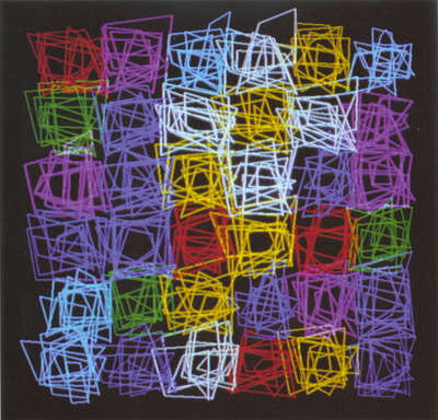
Dialog Between Emotion and Method, 1986.

This is a piece of artwork I saw online by Vera Molnar. I browsed through all the suggested website and I picked this one because it looks least like what I previously imagined a computer can draw. Every other digital artwork is symmetric and futuristic, just like the designs and patterns one would see in a fiction movie. For anyone who doesn’t have any knowledge of what computers are really capable of will expect such a pattern to be generated by a computer.  However, in this piece of work, through all the cluttered lines laying out in squares but these squares are aligned neatly at the center of the canvas, I can actually feel the emotions in such arrangement as if two feelings are tangling together. One explanation could be that messy lines represent one’s struggling while the aligned squares represent the choices he/she has to make. Therefore, I chose to recreate such a feeling through my own code.

To create such mixed feelings, I decided that I don’t want the lines in the squares to be pre-coded because it would ruin the strong twist the picture contained. They have to be randomized so that they can be in contrast with the well-organized squares. Since I did not know a lot about programming in java, I asked one of the learning assistants. However, she told me a random function can never be called outside of draw() and it has to be called inside another function. According to her, if I ever want to draw a static picture, I never am going to generate anything randomly. However, I don’t really believe so because I thought I was only about a number. So I continued searching and tried assigning the value Math.random() returns to a variable I defined and it worked! I told her that even in a static mode, a random function can be called only once. She realized I was right and called me resilient 🙂 After all, I had to find a way because this is all that matters in this art piece. 

Making sure that a line can be generated randomly, I first need to decide how I can color each square with different colors. After noticing that in a single square, all the lines are linked end-to-end, I came up with a program that iterates multiple times. First, the program is going to iterate over the six squares horizontally and vertically, so that all the squares in the pattern will have a go when it comes to generating lines in them. Finally, in every square,  it will loop 10 times to select a point and link the last point to it–of course, it will start with selecting 2 points

After coloring, it looked like this:

Now the colors are also randomly generated by the computer, and the whole work looks somewhat like Molnar’s original work. Here is code 1.1:

size(1400, 950);


background(200);

for(int i=400;i<=900;i = i + 100){  
  for (int k=175;k<=675;k = k + 100){
    int red = (int)(Math.random()*255);
    int gr = (int)(Math.random()*255);
    int bl = (int)(Math.random()*255);    
    stroke(red, gr, bl);
    strokeWeight(2);

    int a = (int)(Math.random()*150) + i - 25;
    int b = (int)(Math.random()*150) + k - 25;
    int c = (int)(Math.random()*150) + i - 25;
    int d = (int)(Math.random()*150) + k - 25;
    line(a, b, c, d);  
    for (int j=1;j<=10;j = j + 1){
    a = (int)(Math.random()*150) + i - 25;
    b = (int)(Math.random()*150) + k - 25;
    line(c, d, a, b);  
    c = (int)(Math.random()*150) + i - 25;
    d = (int)(Math.random()*150) + k - 25;
    line(a, b, c, d); 
    }}}

As a reader can see, although I let every square to occupy 100*100 pixels, I am allowing the points to pop out in the 150*150-pixel area around the area of the square because I want the lines of different squares to intersect a bit, or the whole thing would look segmented and boring.

However, when comparing the mine and the original piece, I can see that every square in her work is obviously more “angular” because even if the lines are messy, they are still following the pattern of going around the square in the same direction, while mine is just random lines going around everywhere. So I thought of a way to refine my code.

To make all the lines go in one direction to form a closed square, I figured I could let the computer choose random points on the four sides clockwise:
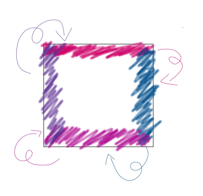
Following is code 2.0 that includes this feature:

size(1400, 950);


background(200);

for(int i=400;i<=900;i = i + 100){  
  for (int k=175;k<=675;k = k + 100){
    int red = (int)(Math.random()*255);
    int gr = (int)(Math.random()*255);
    int bl = (int)(Math.random()*255);    
    stroke(red, gr, bl);
    int a = (int)(Math.random()*150) + i - 25;
    int b = (int)(Math.random()*20) + k - 25;
    int c = (int)(Math.random()*20) + i + 105;
    int d = (int)(Math.random()*150) + k - 25;
    strokeWeight(2);
    line(a, b, c, d);    
    for (int j=1;j<=10;j = j + 1){
    a = (int)(Math.random()*150) + i - 25;
    b = (int)(Math.random()*20) + k + 105;
    line(c, d, a, b);
    c = (int)(Math.random()*20) + i - 25;
    d = (int)(Math.random()*150) + k - 25;
    line(a, b, c, d);
    a = (int)(Math.random()*150) + i - 25;
    b = (int)(Math.random()*20) + k - 25;
    line(c, d, a, b);    
    c = (int)(Math.random()*20) + i + 105;
    d = (int)(Math.random()*150) + k - 25;
    line(a, b, c, d);  


}}}

Now if you run the code, the lines will be organized in a shape that look very much like squares, although not every line will necessarily go clockwise.

However, after everything is properly organized, I feel the pattern is too dull. When I look at my “copycat”, I can’t feel the contrary two feelings in Molnar’s work. I think it is because that I overdid the organizing and the lines are not systematically random now. Therefore, I came up with an idea that adds some “rebels” in code 2.1:

size(1400, 950);


background(200);

for(int i=400;i<=900;i = i + 100){  
  for (int k=175;k<=675;k = k + 100){
    int red = (int)(Math.random()*255);
    int gr = (int)(Math.random()*255);
    int bl = (int)(Math.random()*255);    
    stroke(red, gr, bl);
    strokeWeight(2);
    int a = (int)(Math.random()*150) + i - 25;
    int b = (int)(Math.random()*20) + k - 25;
    int c = (int)(Math.random()*20) + i + 105;
    int d = (int)(Math.random()*150) + k - 25;
    line(a, b, c, d);    
    for (int j=1;j<=12;j = j + 1){
      if (j==5 || j==10){
      a = (int)(Math.random()*250) + i - 75;
      b = (int)(Math.random()*70) + k + 105;
      line(c, d, a, b);
      c = (int)(Math.random()*70) + i - 75;
      d = (int)(Math.random()*250) + k - 75;
      line(a, b, c, d);
      a = (int)(Math.random()*250) + i - 75;
      b = (int)(Math.random()*70) + k - 75;
      line(c, d, a, b);    
      c = (int)(Math.random()*70) + i + 105;
      d = (int)(Math.random()*250) + k - 75;
      line(a, b, c, d);  
      }else{
      a = (int)(Math.random()*150) + i - 25;
      b = (int)(Math.random()*20) + k + 105;
      line(c, d, a, b);
      c = (int)(Math.random()*20) + i - 25;
      d = (int)(Math.random()*150) + k - 25;
      line(a, b, c, d);
      a = (int)(Math.random()*150) + i - 25;
      b = (int)(Math.random()*20) + k - 25;
      line(c, d, a, b);    
      c = (int)(Math.random()*20) + i + 105;
      d = (int)(Math.random()*150) + k - 25;
      line(a, b, c, d);  


}}}}

When you run the code, it looks like this:

Now the squares can look a bit messier than before.

Now, instead of every point has to stay perfectly in the 20*150-pixel box to let the square look recognizable and angular, I am allowing the 5th and the 10th point to get loose a little bit so that the patterns will look a bit wilder. So it makes my final version of the code. I think the final work reflects the emotion I want to express. The messy lines represent the troubling thoughts and the squares imply that while one is experiencing some negative emotions, he/she is also trapped in the social framework or others’ opinions on him/her. One thing that makes this work particularly fun is that when you use the random function in Java, every time you press the run button you’ll get a different result.
Group Project: Individual Reflection by Tya Wang (rw2399)

In my definition, interaction is the process in which two parties involved repeatedly send information through media such as words, sound, image, physical movements, etc, while receiving the other’s information simultaneously. The more types of information are involved, the more interactive this relationship is.  

When I was reading the mandatory materials and articles on the recommended website, I felt that despite the many efforts out there to give a precise definition of interaction, one without specifying the form of information transmission would be inadequate because its forms not only showed the channels from which two parties communicates, the difference in the number of forms is also decisive to people’s interactive experience. In his book The Art of Interactive Design, Crawford (2002) stressed that there should be three repeated steps in an interactive relationship, namely receiving, processing, and sending information. Vivid and brief as what “speak” and “listen” implies in this definition, which probably is the process of giving in and out the information to the other party, it didn’t specify how information is sent and received. This left space for a lot of kinds of communication that may not seem as interactive from my perspective as others according to this definition. For example, although I wouldn’t see the usage of a calculator much of an interactive activityI’m still taking in the calculator’s output, checking it according to my expectations, and putting in another formula. Both my behavior and the calculator’s processing fit Crawford’s definition. However, if we take the channels through which information is conveyed—in this case it’s numbers on the screen and buttons on the panel—we can easily see that there isn’t a lot of complicated information involved in this relationship. However, in a more interactive relationship of communication, there are more senses or channels involved. Take the â€śArtificial Arcadia” created by Fragmentin in collaboration with KOSMOS architects as an example, the landscape of a particular place is shown in 3-D with metal sticks and blanket covers. Visitors are allowed inside for speculation, touching, and an all-around experience of a simulated melting ice and snow in the Swiss mountains. This activity involves transmission of information that activates one’s nearly all senses and gives a complex package of information through the combination of different channels. We could easily see how a relationship like “Artificial Arcadia” that involves more forms of information transmission is more interactive than those with less, such as using a calculator. That’s why I stressed different channels of conveying information in my definition. 

Despite the difference, there is still something that was mentioned both in my definition and Crawford’s. A repeated process that requires information to flow back and forth, or “cyclic”, as Crawford puts it, is indispensable in an interactive process. If the communication of information is only once or twice forward and back, this relationship should be better defined as a responsive relationship. Take the project â€śOpenDataCam 2.0” as an example, the device only requires its user to input the image of an object Then it processes and calculates what it most likely is, gives back the answer, and the end of the activity. There is no repeated information going from the user and the device, and it apparently is more responsive than interactive. On the contrary, in the â€śArtificial Arcadia” project mentioned before, the sticks and blanket change according to the region of mountain its system selected and to when and where visitors come into the project. Information transmission is never absent in this relationship. Therefore, Artificial Arcadia” qualifies as an interactive project yet OpenDataCam 2.0” does not. 

In our group project, we focused on how we want our device to help people imitate the physical motion of another. We first came up with a scenario, a dance class where a lot of people have trouble managing to get the dance move, and then we talked about how to transfer information of the moves from a teacher or a student. We decided that it could be streamed live through a server to make information transmission timely and precise. I think this project resembles the “Artificial Arcadia” project a lot because both involve recording the shape or motion of a person or an object and then sending information to the device to show other people. Therefore, this idea of ours fulfills my recognition of interaction because not only it conveys complex messages of motion, speed, etc., it also allows information to flow back and forth at any time repeatedly. We then focused on the functions and parts of the device itself. In order to make the technology seem feasible, we decided that sensors on each body part would be great for information outputting and inputting. 

However, there is still space for improvements in our project. We first set our scenario and did not explore further later when the prototype is built. We received some great questions from the audience like “have you ever thought of using this in other fields such as medical operation”, and that’s when we thought about the potential of this idea in other fields that we did not show in our performance. We could definitely see this motion syncing device of ours be used in the educational field because it breaks the restriction of distance and makes hands-on experience more accessible to the common.  

Moreover, I think it would be better if our group came up with a feedback system from the students to teachers because that would make the lessons tailored to each student’s needs and make the learning experience deeper. And it also responds to my definition of interaction better because this way the student can provide more information for the teacher to make the communication more like a two-way relationship than simply teaching. These are the two aspects that I think our group could have thought more carefully through during the reflection process. 

Overall, I think our project answers to my definition of interaction and we had a great time together collaborating with each other brainstorming, prototyping and rehearsing for the performance despite the improvements that could have been made. In further projects, I will definitely continue to work in a collaborative manner, taking advice from all channels and seek space to make our ideas better and more comprehensive. 

Reference 

“Artificial Arcadia – Measured and Adjustable Landscapes.” CreativeApplications.Nethttps://www.creativeapplications.net/processing/artificial-arcadia-measured-and-adjustable-landscapes/. Accessed 9 Oct. 2019. 

Crawford, Chris. The Art of Interactive Design: A Euphonious and Illuminating Guide to Building Successful Software. 1 edition, No Starch Press, 2002. 

“OpenDataCam 2.0 – An Open Source Tool to Quantify the World.” CreativeApplications.Nethttps://www.creativeapplications.net/environment/opendatacam-2-0-an-open-source-tool-to-quantify-the-world/. Accessed 9 Oct. 2019. 


Recitation 3: Sensors by Tya Wang (rw2399)

In this section, we tried out several sensors to see which information from real life could be translated into electrical signals using circuits. The codes were basically all the same except some tiny revision. However, although I thought building these circuits only involve changing the sensor part, some problems still occurred during this recitation. This led me to reflect on how well I actually understand the whole idea behind the pre-made diagrams.

Circuits

Materials:

1 * Arduino Uno
1 * USB A to B cable
1 * breadboard
1 * buzzer
1 * LEDs
1* Moisture sensor
1* Ultrasonic sensor
1* Vibration sensor
A handful of jumper cables

Sensor 1: Moisture sensor

The moisture sensor is a small device that has three ports, each goes to one in GND, power, and pin. It works by returning a value that represents how moisture it is on the device. When it is not at all moisture, it returns 0 and the value increases when in touch with more water (it has a max value though).  We uploaded the AnalogRead code to read the value returned by the sensor. This device can be used in settings that involve controlling how wet something is such as auto watering when the soil is dry. However, the device is not very sensitive because when we breathe to it, it didn’t change a large value,  although there was vapor in my breathe.

Here is how we are changing values returned by the moisture sensor in a lab:

Sensor 2: Vibration sensor

This sensor returns how strong the vibration is on it. We used the special “knock” code so that the string “knock!” is printed on the serial panel. The code is pretty simple, however building the circuit is kind of tricky. Because we built a circuit with a sensor that had three ports before this one, we couldn’t really take that sensor down and plug the vibration sensor in directly. Moreover, we needed to add an additional resistor as well as another output device into the circuit. We chose the LED, and successfully fried it because we had it in parallel with the resistor and sensor. When breaking it gave a soft but horrifying blast sound and an unpleasant smile. Lesson learned. 

This is the sad scene of a broken LED:

The broken LED

After consulting an instructor, I learned that to adjust the brightness of the LED using values returned by the sensor, we don’t really need to connect them in one single circuit. We can actually code it and give it an output value mapped from the input analog value. This is the part of this section that actually deepened my understanding of how Arduino worked in real life.

Following is the video of a working vibration sensor:

Sensor 3: Ultrasonic sensor

We would like to get a joystick yet all three of them are on lease. So we got our second choice. This is quite easy to put together because there are no other electronic parts related and the codes are already done. Since it calculates distance based on ultrasonic, it should be more accurate than the infrared one. It is indeed quite smooth, just sometimes it is quite hard for a user to keep track of the changes of a value when information is displayed on the serial panel in the form of horse race lamps. I wish there were a user’s interface or something that I could just read the values from one box without unnecessary information. This is one part of coding that I want to learn in the future using C.

Reflections

What did you intend to assemble in the recitation exercise? If your sensor/actuator combination were to be used for pragmatic purposes, who would use it, why would they use it, and how could it be used?

We intended to assemble a circuit that takes the input from the sensors and gives this input back to the computer. Then the computer or the circuit makes an output in a certain way using the input value.

The vibration sensor could be used to detect whether people has walked through it. So we can use it to build a floor light that automatically turns on when people pass by. It can be assembled in a family to build switchless light systems.

The moisture sensor can be used in a sauna house to track if the sauna room is too wet. When visitors hate it wet in the room, the room can automatically turn on its dehumidification device.

Code is often compared to following a recipe or tutorial.  Why do you think that is?

Because when we cook following a recipe, we do the instructions step by step from bottom to top. And when the computer is executing the codes, it runs from the first line to the last unless specified.

In Language of New Media, Manovich describes the influence of computers on new media. In what ways do you believe the computer influences our human behaviors?

Sometimes computers detect and give feedback to help us better track our own status and behavior. Using computers, human can have a better insight into what they are doing and check continuously whether their behavior meets their expectation of themselves.

Recitation 2: Arduino Basics by Tya Wang

We got our own Arduino kits in this recitation. I felt so good building these devices using my materials although I’m still assembling circuits based on instructors’ ideas. This time we combined programming and working on circuits to carry out more complicated projects. Since Inmi told us in class that we are going to try out the if clauses in this recitation and I’m worried that I might be overwhelmed by all the logic and syntax, I previewed the codes before recitation. This has made this recitation pretty smooth and efficient for me. I don’t have to try understanding everything while paying attention to the physical electronic parts. I think this will always be a great strategy to take when it comes to coding that I’m not proficient in.

Circuits

Materials

1 * Arduino Uno
1 * USB A to B cable
1 * breadboard
1 * buzzer
2 * LEDs
2 * 220-ohm resistors
2 * 10K ohm resistors
2 * pushbuttons
A handful of jumper cables
2 * arcade buttons

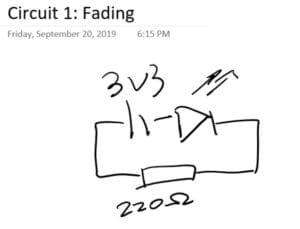
Circuit 1: Fading

We directly used the example code from Arduino after talking about what it does.  We both agreed that this code is walking the led back and forth from dim to bright by changing the PWM value sent to it using an if clause to see whether the value should go up or down, changing the brightness of light in the meantime. Therefore, we did a pretty simple circuit: linking LED to pin 9 as the example code suggests, using a 220-ohm resistor and plugging in the power source and it worked–that simple:/

Circuit 2: Buzzer

Still, the most challenging part of circuit 2 is understanding the code, since there is a new clause of for in it, and uses the function tone() that asks buzzers play music. Circuit-wise, we just needed to notice that the buzzer is polarized and pay attention to which direction electricity flows.

We searched online and it says for in C works this way:

for ( init; condition; increment ) {
   statement(s);
}

So we understood that the example code is trying to play the melody once by iterating over each note’s melody and duration by using the tone() function every time the board is reset. We looked up the reference in the toolbar, and we noticed that the third argument in tone() is optional, therefore we could also stop the buzzer playing using noTone() function. This means we can also write our song as to let the buzzer play as long as we could make out each note in it. 

Circuit 3&4: Speed game

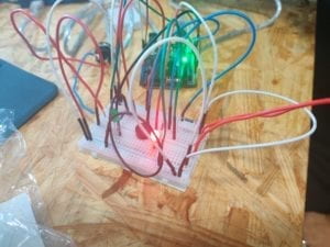
The third circuit is a fun but complicated one, especially when you put into the third and fourth players. But after we figured the code out, it seemed quite simple especially when the blueprint of the circuit is already there to be referred. This is what our circuit for two players looked like at first. The serial panel is only showing the record of player 01 pressing the button, and that’s when we realized an error occurred when we were building the left side of the circuit. We did a little troubleshoot around the second button, and it didn’t take us long to find out it was just a minor mistake of connecting both sides of the button to ground. It’s always more efficient to figure out what’s wrong if you have a primary idea of which part of the project is troublesome.

After we fixed the problem, the circuit worked pretty and smooth.

For the last 15 minutes of the recitation, we worked together with the group of Lisa Moon to build the game for 4 players. I and Lisa did the same change to the code, which was basically copying and pasting lines to assign new pins for the other 2 buttons and to record if player 3 and 4 have pressed their button, since the original logic of the code is to check when player 01 press the button and win 1 point, whether he/she has reached 10 points in all in order to champion the game, provided the other players have not championed yet. And then player 02, 03, 04… (So the program is not actually fair because if there are multiple players pressing the button exact the same time, whoever is checked first by the program always gets 1 more point) Therefore, we just need to add the sentences for player 03 and 04 to make the program work.

Our final result is quite wild.

Reflections

Reflect how you use technology in your daily life and on the circuits you just built. Use the text Physical Computing and your own observations to define interaction.

Interaction is the process in which two parties involved repeatedly send information through media such as words, sound, image, physical movements, etc while receiving the other’s information simultaneously. The more types of media are involved in the communication of information, the more interactive a relationship is.

Why did we use the 10K resistor with the push button?

Because the push button does not has ohms on its own. Since the voltage is how large we chose it, the smaller the resistor value is, the stronger the current it. In order not to fry the button with too strong a current, we need to put a resistor with a large value into the circuit.

If you have 100,000 LEDs of any brightness and color at your disposal, what would you make and where would you put it?

I think I will find a vacant space in the countryside of Shanghai, lay them on the ground into aircraft lanes, and run an open bid to let the company that offers the most money to build an airport next to it.

Recitation 1: Electronics and Soldering by Tya Wang

In the first recitation, we tried soldering in person to take a peek at how circuits are connected together. Also, we built three circuits on a breadboard with detachable wires and parts in order to learn about how electricity and breadboards work. These exercises ware both a warm-up for this course and a foundation of working with Arduino boards.

Circuits

Materials:

  • 1 * Breadboard
  • 1 * LM7805 Voltage Regulator
  • 1 * Buzzer
  • 1 * Push-Button Switch
  • 1 * Arcade Button
  • 1 * 220 ohm Resistor
  • 1 * 10K ohm Resistor
  • 1 * 10K ohm Variable Resistor (Potentiometer)
  • 1 * LED
  • 1 * 100 nF (0.1uF) Capacitor
  • 1 * 12 volt power supply
  • 1 * Barrel Jack
  • 1 * Multimeter
  • Several Jumper Cables (Hook-up Wires)

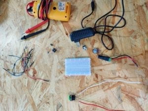
Below is a picture of all the materials:

Circuit 1: Door bell

doorbell

Interestingly, the first exercise for me and my partner was the most difficult because neither of us understood how a breadboard works. At first, we connected power to one side of the board and ground to the other side, because I thought both sides would be the same. And we also put the electronic parts parallel with the rows that electricity flows through. We didn’t understand what was going on until the instructor explained to us that the lines are connected electronically and the two sides of the board are not connected at all. These are two of the most important takeaways from this recitation session.

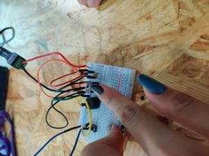
This is how our final circuit looks like:

We struggled to make out the difference between the three feet of the transistor. When electricity is flowing through, the temperature on the transistor may be very high.

Circuit 2:  Lamp

lamp

After understanding how circuits and breadboards work, building the second circuit became way easier for us.  We used the button we made during soldering into the circuit to make switching it on and off easier. We don’t need to limit ourselves to the factory manufactured electronic parts. We can actually design and make parts tailored to our preference.

We didn’t really have time for the third circuit in class. But we talked through how to use a variable resistor in this diagram.

Reflections

After reading The Art of Interactive Design, in what way do you think that the circuits you built today include interactivity? Please explain your answer.

I think that the circuit respond to human’s switching and off immediately by its output devices. The three steps of the process of using these devices fit into the model of interactivity given by the author: the circuit first wait for the user to give an instruction of what to do and record the signals, the user gives his/her decision of whether to switch on or off, and finally, the circuit gets the instruction and executes it. However, according to the definition, I think a complete interactive product need to have more back and forth in these responses and the two parties’, and the expression of ideas and information should be more complicated than a simple on/off.

How can Interaction Design and Physical Computing be used to create Interactive Art? You can reference Zack Lieberman’s video or any other artist that you know .

In Zack Lieberman’s video, the device has a sensor attached on it to record the motion of human. And by computing and analyze the data gathered by these sensors, an output device can then perform another motion or give some feedback. In the case of eyewriter, the feedback would be the image generated by the software or the picture projected onto the building. Art can be created this way in a sense that either interaction design and physical computing use technology to help human create art in the traditional forms, or their output itself represent a new type of art.