Midterm Project-Snowball-Leah Bian-Eric Parren

Project title: Snowball

Leah Bian

Professor: Eric Parren

I. Context and Significance

     In the group project, our team made a “painting machine” that could record a person’s day with body data. It was our first attempt to apply our personal definition of “interaction” into a physical thing. We implemented the idea of “input, processing and output” in the project, and tried to show the interactive process clearly. My definition of “interaction” also developed in that experience. In the individual reflection for the group project, I listed two projects that I researched online——OpenDataCam 2.0, and“Sharing Faces”.  I wrote in my reflection that interaction should be separated into two parts: physical interaction and emotional interaction. Emotional interaction involves emotions, humanistic feelings and aesthetic value. In my opinion, high-level interactivity should combine these two parts of interaction organically.

     Before I started working on my midterm project, I did some research online to further my understanding of “interaction”. Light Kinetics, a project created by Madrid based creative studio Espadaysantacruz, inspired me. It is an interactive light installation where the behavior of light is controlled by a physics simulator. According to the author Filip Visnjic, “the initial impulse is regulated by the strength of the tap, creating a very natural interaction. When one hits hard light moves fast and can overcome the force of gravity, when one hits the bulb softly light falls slowly along the top.” That is to say, the user’s behavior could directly affect the way that the device works. From my perspective, the biggest problem of some interactive devices is that the output is determined by a preset program, instead of being affected by the external behaviors. Therefore, a highly interactive device should allow the user to really engage in the interaction, instead of excluding them as the audience or actors.
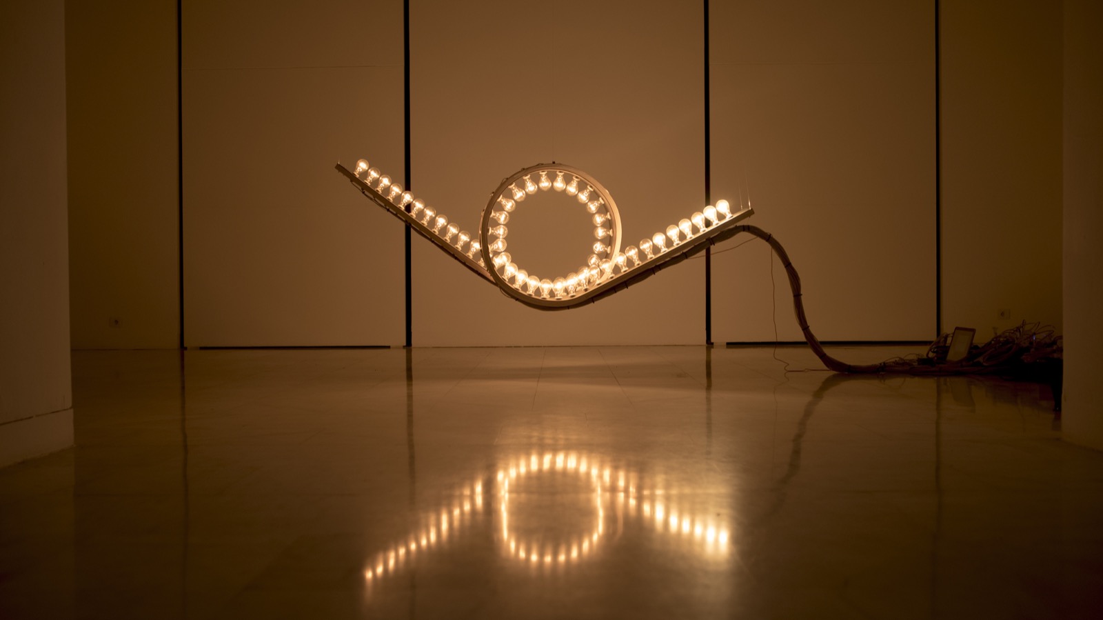
Light Kinetics

   II. Concept and Design

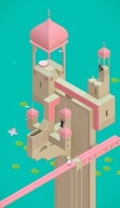
    When we were still struggling with the brainstorming of the project, my partner Eric proposed that we could build a maze in which the LEDs along the path would bright up with the character in the maze moving. Then, an idea bumped into my mind that we can build a three-dimensional maze instead of one that is on a two-dimension plane. I thought of Monument Valley suddenly. It is an indie puzzle game developed and published by Ustwo Games. The player should discover the hidden paths, and lead the princess Ida (a game character) through mazes to various platforms, and the mazes are designed as castles. We decided to make the game real with 3D printing and Arduino. The project do not have an intended audience, since the game allow people of different ages to engage with.
0
Monument Valley

    At the beginning, we thought for a long time about what to use as a replacement for princess Ida in Monument valley. We wondered whether we could let the player complete the maze without using any characters, but it would lead to some problems. For example, without a character, the player cannot know whether the paths are connected correctly, and it would be hard to tell what is the correct order of connecting the paths. In addition, the goal of completing the game would be vague, and the player cannot gain a strong sense of accomplishment. Therefore, we raised our concerns and the IMA fellow Jingtian gave us some suggestions. She advised that we can use a small ball as the substitute, and the player can control the movement of the ball by shaking the KT board stuck to the bottom of the “castle”. This suggestion helped us a lot in developing the basic ideas and concepts.

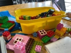
    In addition, we thought for long about what materials to use to build the maze, since we were concerned that it would be too complicated to build the castle only with 3D printing. Then, we considered using cardboard and Lego. We looked up some information about cardboard craft online and went to a Lego stationary store to look for possible materials. However, we found that the cardboard was unstable and somewhat crude, and the types of Lego models were limited, making it difficult to fit the circuits that we need to install on the castle. Therefore, we finally decided that we would build the castle only with 3D printing. It was a challenge, but we were both excited about it.
0
test with Legos

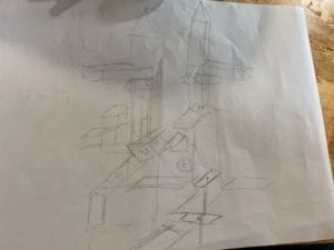
After we decided those basic ideas, we began to design the specific levels of the maze. We decided to make the maze consist of the following three parts:

  1. Control the two paths with buttons, let them turn 90 degrees respectively, then let the two ends of the paths meet.
  2. Let the small ball fall through the hole, hit the touching sensor, and then let the short path turn 90 degrees.
  3. Use the potentiometer to rotate the triangular prism.

Note: The paths will be stuck to the servos with hot glue.

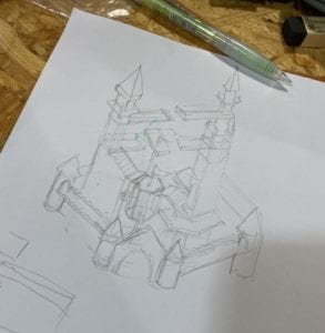
These are the two sketches that I drew as the plan during the development of ideas:
0
sketch (first version)


0
sketch (second version)

    We also developed some other ideas for the game:

  1. The LED installed beside the button/sensor/potentiometer will bright up when the player has connected the paths correctly.
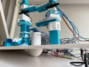
  2. The small ball will fall from the upper layer to the lower one though the holes.
  3. Half of a 3D-printed ball will be stuck to the board to help the player shake the board smoothly.
  4. The small ball will roll from the top layer to the KT board at the bottom.
00
the base

III. Fabrication and Production

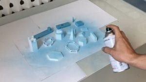
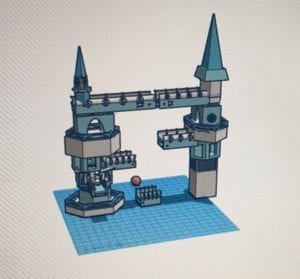
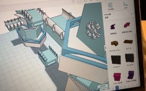
We started to work on the 3D printing part on Tinkercad with the sketches. At first, I was not skillful with it. But with the help of IMA fellows, I understood the basic process of 3D printing and reviewed those commonly used editing methods. We measured the sizes of the circuit components and designed our castle in its final form on Tinkercad. However, we did not realize that 3D printed objects need supporter. In our imagination, the final 3D printed castle should be printed in a complete way based on the model directly, and should be in the corresponding colors. But the reality is not like that, so we were quite surprised when told that we had to print all the components separately. It can be counted as our first failure in our first attempt at 3D printing, but it was a progress as well. After making some modifications to the model, we printed more than 20 components separately. Besides, to solve the problem of the insufficient supply of blue plastic, we sprayed some components into blue with sprayer cans, and found it quite interesting.
0
preview
details
0
sprayer can

    In the process of building the model, we came up with a delicate concept—— “snowball”. Since our castle is designed in the tone of white and light blue, and the small ball will roll from the top to the bottom, it fits the concept quite well. Therefore, we 3D printed a little white ball as our “snowball”.

    In the Arduino part, we successfully let the code run. However, we found that the “snowball” that we printed was too light to be sensed by the touching sensor when it falls from the upper layer. Therefore, we used a glass ball as the substitute. We reprinted the paths that can fit the size of the glass ball, and painted the glass ball into white. But we were disappointed when we found that the glass ball could not trigger the touching sensor either, then we realized that it may be due to the problem of the contact surface, instead of the weight. We gave up this idea, and decided to let the player look for and press the touching sensor directly.

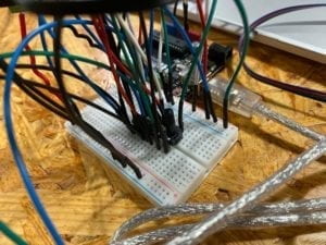
    In addition, we started building the circuits with four Arduino Unos and four breadboards. However, we found that this seemed too cluttered and difficulties might exist in running the codes at the same time. Professor Parren suggested us to build the circuit on one larger breadboard and one Arduino Uno, so that we can make it simpler. We made it successfully, and solved the problem of running the four codes at the same time by putting them in one file.

     We were really lack of time before the user test. We barely managed to assemble all the printed parts together and successfully finished the programming of four circuits. We used solder to connect the LEDs, buttons and the breadboard together. However, we found that the space reserved in the 3D printed paths was too small to fit the LEDs and buttons in exactly the right place. In addition, since we only used one breadboard, the wires were intertwined. They were likely to touch each other or disconnect. These were the problems that we already discovered before the user test, but we did not have the time to solve.
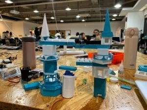
0
before user test

  On the user test day, only two of our four circuits could work normally due to the problems that I mention above. Therefore, we could only verbally describe the basic concepts and the game rules during the user test. Although it was a pity, we still received some valuable suggestions. For example, we can tie the wires together or stick them on the KT board to solve the problem of the tangled wires; write an instruction to make the game rules clearer; add a reset system to ensure a quick reset of the device for the next round…

We adopted these suggestions, and made the following adjustments:

  1. We reprinted the top two paths and moved the holes for the installation of LED and button to the side near the rotation axis, so that we can prevent the wires from being dragged by the path movement.
  2. We rebuilt the four circuits on four separate breadboards, that were originally placed on only one bread board, to alleviate the problem of the tangled wires and make them clearer visually for possible future adjustments.
  3. We wrote a simple yet implicit instruction to indicate the rule of the game for the players, while retaining the difficulty (let the player to explore).
  4. We built a reset system. Pressing a button at the end of a game can restore all four circuits at the same time.
  5. We installed a buzzer. When the player successfully connect all the paths, the automatic play of music will inform the end of the game.
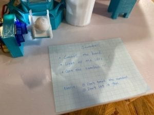
0
instruction

We tested the circuits without the 3D printed components, and they worked well.

Final Version and Final Test:
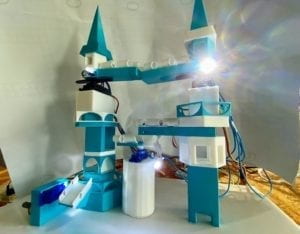
0
final version

IV. Conclusions

The goals of our project include: (1). Enabling players to actively seek solutions to solve the maze based on careful read instruction. (2). Let the user interact with our device by both physically controlling the KT board and exploring the hidden Arduino mechanism. Our project aligns with my definition of interaction well. It not only shows interaction on the physical level, but also reflects the aesthetic value. In addition, the output of our device is not based on the preset program, but is affected by the player’s operation and choice. While discovering the hidden buttons, sensors, and potentiometers, our players can also get a sense of surprise and accomplishment of mystery solving. On the presentation day, however, our assigned user had some difficulty in understanding the rules of the game. On the instruction note, I wrote “control the board”, but he misunderstood the board as the touching sensor, so we had to give a hint. This may be due to the reason that our instruction was a bit too vague, and it takes time to let the user understand the indication of the words we chose. In addition, Professor Parren suggested that we can hide the wires with some cloth or put them in the box since they looked messy. And we can add some handles on the KT board so that it will be clearer to the user that he can control the board. If we have more time, we will practice these two suggestions, and think more deeply about how we could retain the difficulty of the game, while making it easier for the user to understand how the whole thing works.

I have really learnt a lot from this experience. From my perspective, the most important part of the whole project is the initial concept and design, and secondly, how to make choices in every step of practice. Our personal definitions of “interaction” directly affects the conception of our project, and every choice we make should treat “interaction” as the priority. We should set high expectations of the final completion of the project at the beginning to ensure the expected highest quality. In real practice, even if some parts are sacrificed due to technical problems, the overall interaction of the device should not be weakened. We should view our project from the perspectives of the user and ask for suggestions, instead of blindly following our preexisting imagination of the concept. It helps us to find the problem, and reminds us to ensure the level of interaction. In addition, in the whole process, I also realized the value of meticulosity and accuracy. In 3D printing, one problem of measurement leads to the reprint of the whole thing. In programming, one character’s missing means the failure of the entire code. These details are the most essential parts that determine the success or failure of a project.

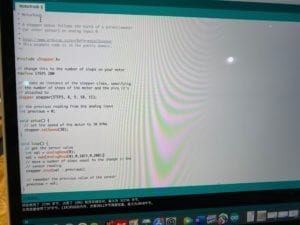
A video of the codes is attached below:

References:

OpenDataCam: https://www.creativeapplications.net/environment/opendatacam-2-0-an-open-source-tool-to-quantify-the-world/

Sharing Faces: https://www.creativeapplications.net/openframeworks/sharing-faces-seeing-yourself-reflected-in-the-image-of-others/

Light Kinetics: https://www.creativeapplications.net/processing/light-kinetics-interactive-light-using-a-physics-simulator/
Recitation 4: Drawing Machines——Leah Bian

In this recitation, we created a drawing machine by using an H-bridge to control stepper motors attached to mechanical arms. We need to build the circuit and edit the code individually, and work with a partner to build the final drawing machine.

Materials:

For Steps 1 and 2

1 * 42STH33-0404AC stepper motor
1 * L293D ic chip
1 * power jack
1 * 12 VDC power supply
1 * Arduino kit and its contents

For Step 3

2 * Laser-cut short arms
2 * Laser-cut long arms
1* Laser-cut motor holder
2 * 3D printed motor coupling
5 * Paper Fasteners
1 * Pen that fits the laser-cut mechanisms
Paper

Step 1: Build the circuit

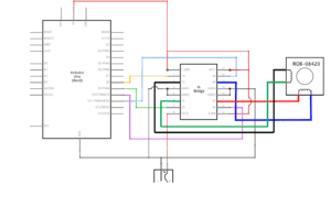
The circuit was quite complicated, and we had to be extremely careful when building it, since we were working with higher voltages compared with the past ones. It was a challenge for me to get the 5V into all the ports that needed to get it. I asked my partner about the connections between grounds and successfully worked them out. After finishing the circuit, I asked an IMA assistant for help. She helped me check the circuit again, and we found that I placed the H-Bridge upside down. Fortunately, I didn’t upload the code without the second check. After I corrected the mistake and upload the code, the motor rotate smoothly.

0
circuit diagram

Step 2: Control rotation with a potentiometer

In step 2, I added a potentiometer from my kit to the circuit as the analog input. Then I uploaded the MotorKnob (Arduino>File>Examples>Stepper>MotorKnob) example to control the motor, and modified the number of steps within the code to 200, given that Stepper Motor is a 200 step motor. I met some problems when adding the function “map()”, because I am not familiar with the principle of this function. With my partner’s help, I successfully worked it out.

0
potentiometer
0
the code

Step 3: Build a Drawing Machine

After my partner and I both finished Step 1 and Step 2, we started working together. We collected the materials needed and built the drawing machine successfully. It didn’t take much work. We then drew by spinning the potentiometers, which were controlling the movement of the motor.

Question 1: What kind of machines would you be interested in building? Add a reflection about the use of actuators, the digital manipulation of art, and the creative process to your blog post.

Answer: I am interested in building a tiny moving maze. It is actually a game machine and the player have to exit the maze within a specific time limit or the path of the maze will change. The actuator would be the stepper motor to allow the walls in the maze to move smoothly. The user will use potentiometers to control the movement of the player character. LEDs would be installed in the maze. They are supposed to serve as the marker to show the player’s location, thus enhancing the interactivity between the user and the machine.

Question 2: Choose an art installation mentioned in the reading ART + Science NOW, Stephen Wilson (Kinetics chapter). Post your thoughts about it and make a comparison with the work you did during this recitation. How do you think that the artist selected those specific actuators for his project?

Answer: In the reading ART + Science NOW, Stephen Wilson (Kinetics chapter), I found the art installation Open Burble quite interesting. In this recitation, we built a drawing machine that enables the users to create an art piece and express themselves through a third-party, which is similar to the Burble. The Burble is controlled by people via electronic handlebars, letting them to create something at an urban scale. Open Burble is made out of modular inflatable balloons with sensors, LEDs, accelerometers and microcontrollers, creating a highly interactive system. These actuators satisfy the artistic expectation while enabling the whole system to run smoothly.

Individual Reflection——Leah Bian

“ Interaction: a cyclic process in which two actors alternately listen, think, and speak” (5). —— Crawford used this concrete example to define interaction. To explain it in a more academic way, we can replace listen, think, and speak with input, process, and output. I do agree with this inspiring analogy, but I still consider it as a bit vague. From my point of view, interaction should be separated into two parts: physical interaction and emotional interaction. Physical interaction is clear and manifest in the structure of a design, while emotional interaction involves emotions, humanistic feelings and aesthetic value. High-level interactivity should combine those two aspects organically. In most cases, low-level interactivity only focus on the former.

   To interpret my understanding of “interaction”, I want to use the two projects that I researched as examples.

  The first project is named as OpenDataCam 2.0. It consists of a camera attached to a mini computer that is running an object detection algorithm that counts and tracks moving objects. On the software sideOpenDataCam is running YOLO, which is trained to detect objects in images (Filip Visnjic). The aim of this project is to quantify the world. There does exist interactivity, since the attached camera inputs data to YOLO and YOLO outputs all objects in each frame. However, it is not really convincing that OpenDataCamis a highly interactive project, which is probably because of the reason that there are scarcely any emotions, humanistic feelings or aesthetic pleasure. The interaction here is “cold” and “pale”. 

0
OpenDataCam Poster

  The second project I want to mention aligns to my definition better, which is called “Sharing Faces”. It used a megapixel surveillance camera and custom software to match the face locations of the person looking at the screen. As the person moves, new images are pulled from the database matching the new location and create a mirror-like image of the user using the images of others (Filip Visnjic). Kyle McDonald, the project designer, said that the project was inspired by a story from the history of Rome. Two tribes went into war with each other and finally realized that they were all literally brothers. Moments of reflection on the nature of our connectedness made Kyle moved, and the project was thus created. The interaction here is not only about digital cameras, software, programming and machine building, but also focus on the interaction in the experiencers’ emotions. These two aspects of interaction interweave with each other, creating a touching and technologically advanced project.

0
“Sharing Faces”

  The project of our group is named as “Paint Your Day”, in which we designed a system that keeps collecting body data’s from the user and will create a painting when the day ends. At the beginning of our first group meeting, we were all at a loss since we did not know where to start. Then, we decided to share our personal definition of “interaction” and discuss the focus of our project. We all agreed that we should involve the element of “emotion” and make our project more artistic. The original conception was to create a painting by voice pitch, but it was turned down later since it is hard to be practiced. The final plan was like this: the user starts his/her normal day, wearing a smartwatch; the smartwatch keeps inputting the user’s body data to the computer; the computer then analyzes and processes the data; the output will be a beautiful painting depicting the user’s day based on the processed data. This process shows the physical interaction of our project clearly. In addition, the user’s emotions during the day could be detected by the computer through the body data and be directly revealed in colors, shapes and lines, providing a new approach of recording one’s day. Painting is part of art, and art itself is emotional. Our project also shows humanistic feelings and brings aesthetic pleasure to our users. We successfully combined the physical and emotional interaction together, which aligned with my definition of “interaction” well.

References:

Crawford, “What Exactly is Interactivity,” The Art of Interactive Design,  pp. 1-5.

OpenDataCam: https://www.creativeapplications.net/environment/opendatacam-2-0-an-open-source-tool-to-quantify-the-world/

Sharing Faces: https://www.creativeapplications.net/openframeworks/sharing-faces-seeing-yourself-reflected-in-the-image-of-others/

Interaction Lab Recitation3——Leah Bian

In this recitation, my partner Eric and I chose the infrared distance sensor and build a circuit that integrates it with my Arduino. The basic information of the infrared distance sensor is listed below.

“Similar to the Moisture Sensor, the Infrared Distance Sensor can by used by implementing the connections and code from a simple analog read sketch. In the case of Infrared Distance Sensors, using the “map()” function can be helpful.  This function maps the analog readings from the sensor to the distance between the sensor and the object.”

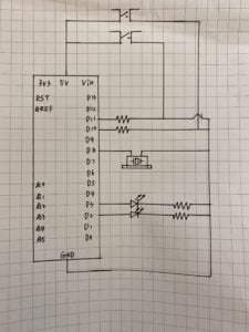
After reading this material given on the recitation website, we decided to use one LED as the output of our circuit, hoping that the light of the LED could show the distance from the sensor to the object. We started to build the circuit and the diagram is shown below.

diagram
diagram

Materials:

1* Arduino Uno

1* breadboard

1* LED

1* 10K ohm Resistor

1* infrared distance sensor

wires

At first, we have no idea what is the “object” mentioned in the material above and we don’t know how could the sensor measure distance from the object to itself. Therefore, we asked Professor Eric for help. He gave us a detailed explanation and we finally got some basic ideas.

After we finished the building of the circuit, my partner Eric made some modifications in the code to let the LED work. However, it seemed that there was something wrong with the sensor since the LED was not changing the brightness with the distance.

Again, with the help of Professor Eric, we discovered that the failure was due to one error in our code—— we used “digitalWrite” instead of “analogWrite”, so  that the light could only be on or off. After we corrected the error, the circuit finally worked.

Questions:

Question 1: What did you intend to assemble in the recitation exercise? If your sensor/actuator combination were to be used for pragmatic purposes, who would use it, why would they use it, and how could it be used?

Answer: My partner and I decided to build a circuit in which the light of the LED could show the distance from the sensor to the object.To utilize it in real life, we can make it as an alarm. If someone is unconsciously approaching a dangerous object, the light will get brighter and brighter.

Question 2: Code is often compared to following a recipe or tutorial. Why do you think that is?

Answer: The operation of a code needs to follow an specific order, and every step of it is important. Even one small error in the code could lead to the failure of operating it, which is similar to the process of cooking.

Question 3: In Language of New Media, Manovich describes the influence of computers on new media. In what ways do you believe the computer influences our human behaviors?

Answer: After the third revolution of science and technology, the computer has become a crucial part of human life. The development of it greatly enhanced the human productivity, providing more convenient methods to collect information, solve real life problems and create new inventions. Humans tend to rely on computers for help, which is due to the huge impact of the internet to a great extent.

Interaction Lab Recitation 2——Leah Bian

In the second recitation of interaction lab, my partner Eric and I built three circuits: Fade, toneMelody, and Speed Game, using our own Arduino Kit.

Materials:

From Arduino Kit:

1 * Arduino Uno
1 * USB A to B cable
1 * breadboard
1 * buzzer
2 * LEDs
2 * 220 ohm resistors
2 * 10K ohm resistors
2 * pushbuttons
A handful of jumper cables

From cart:

2 * arcade buttons

Circuit 1: Fade

circuit1
circuit 1: Fade

Code: Arduino>File>Examples>03.Analog>Fading

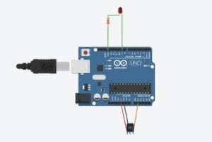
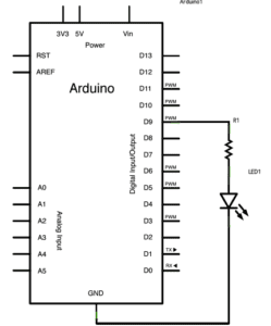
The first circuit is quite simple. What we need to connect the LED with a resistor to make its light fade. We didn’t have any trouble in building this circuit and finished it quickly.

Circuit 2: toneMelody

toneMelody Arduino Schematics
circuit2: toneMelody

Code: Arduino>File>Examples>02.Digital>toneMelody

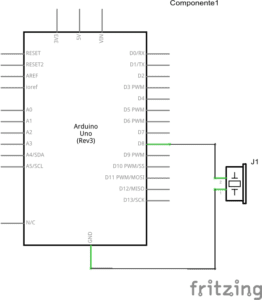
The second circuit is also very simple. After we finished it, my partner suggested that we could put the code in the “void loop” function to make the melody played repeatedly. We successfully made it, and were quite excited to find it worked.

Circuit 3: Speed Game

circuit
circuit diagram
circuit
schematic for circuit 3

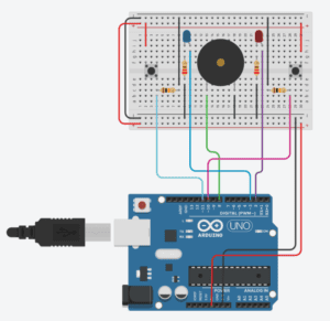
The description of the game: This is a two player game where each participant races to click a button more than their opponent. After 10 seconds, whoever has clicked their button the most and fastest wins! 

This circuit is the most complex one among those I have encountered. It took us about 20 minutes to let it work successfully. After we finished building it for  the first time, we found that it was not working. We examine the circuit that we built carefully and found that we added a wrong wire. We fixed the problem and successfully finished it. 

Circuit 4: Four-player Speed Game

We spent too much time on building circuit 3. As a result, we didn’t have time to build circuit 4. 

Question 1: Reflect how you use technology in your daily life and on the circuits you just built. Use the text Physical Computing and your own observations to define interaction.

Answer:  

Technology exists everywhere in modern life, even if we haven’t realized this fact. We enjoy the convenience that technology brings us, but seldom thinking about the operating system behind these “machines”. While building those circuits in the recitation, I directly contacted the algorithm and programming hidden in the systems and realized how complex they are.

According to  Introduction to Physical Computing, our interaction with computers consists of three parts – “input, output, and processing”. In my opinion, interaction is the process of information transfer and the coordination of the various components. Interaction brings magic.

Question 2: Why did we use the 10K resistor with the push button?

Answer:  10K is a high resistor value, which enables a low current to pass the circuit, thus protecting the circuit.

Question 3: If you have 100,000 LEDs of any brightness and color at your disposal, what would you make and where would you put it?

Answer:  I will put those LED along an originally dark alley, making it glittery. It will light up the path, and make those who pass through this alley every day feel warm and safe.