Puppet-Leah Bian-Eric

Project name: Puppet

Conception and Design

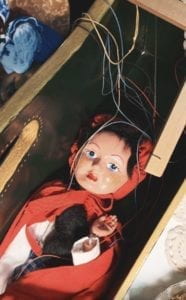
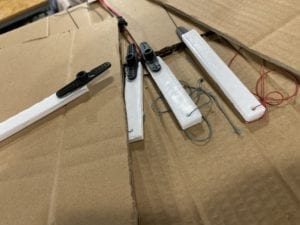
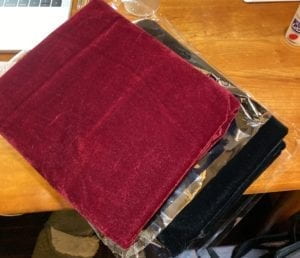
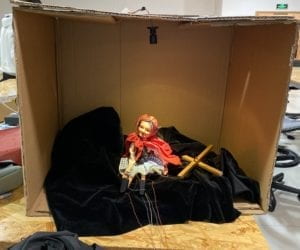
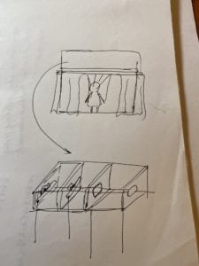
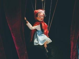
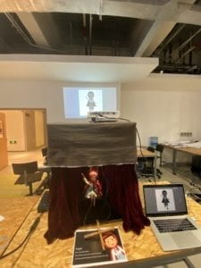
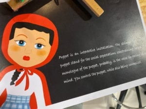
The final goal of our project was decided at the beginning, which is to show the theme of “social expectation”. The original thought was to let the user play the role of the various forces in the society that force us to behave in a certain way, and the puppet is the representation of ourselves, who are being controlled. Therefore, the original plan was to let the user set a pose for the puppet in Processing, and thus data of the pose would be sent to the Arduino part. The real puppet on the miniature stage would first change several random poses, and finally stay at the pose that the user set before. In the first week of the process, we started to prepare the materials needed for the project with the original plan in mind. The most important part in our project is the puppet. We tried to search for one that is not so funny or childish to make our theme more distinctive, and finally decided to buy the vintage puppet that has 30 years history. We expected that the final stage may have a quite large size. If we use laser cutting to build the stage, then the materials may be insufficient. Therefore, we finally decided to use cartons as replacement. To add some dramatic atmosphere of our stage, we bought some velvet, expecting to stick them to the stage surface. In addition, we bought a mini tracker lamp to be attached to the top of the stage. For the Arduino part, we decided to use four servos connected with strings to rotate the arms and legs of the puppet. To make it more stable, we decided to use 3D printing to print some components and stick them to the servos with hot glue. In addition, we used some red velvet to make the stage curtain. Since it requires professional skills, we sent the velvet to a tailor shop, and finally got a satisfying result.

0

0

0

0

Fabrication and Production

To create the image of the puppet in Processing, I tried to draw a cartoon version of the puppet by coding at the beginning. But I finally gave up since it was too complicated and the final result may even not be satisfying due to the limitation of coding. Therefore, I decided to draw the image in a digital painting app name as Procreate. I can draw different parts of the puppet’s body in different layers of the painting screen, and thus we can directly load the images into Processing and rotate them. We first chose to use keyboard and mouse interaction to let the user control the movement of the digital puppet, and we finally finished the code. However, when we shared our thoughts with the IMA fellows, they pointed out that it would be hard for the users to see our theme of social expectation with such a simple process. Besides, it may not make sense to control the puppet with Processing instead of directly controlling it. The digital puppet and the physical puppet are presented to the user at the same time, and it looks a bit competitive. From our own perspective, we also felt that the interaction in our project was a bit weak, and the theme seemed to be vague. Therefore, we modified the plan. We planned to make our stage curtain an automatic one. We could use the motor to twine the string connected to the front of the curtain, thus opening it. Besides, I changed the color of the image in Processing to black and white tone. We could cast it on the wall with projector and it would look a huge shadow hanging over the real puppet.

    However, our plan changed again after user testing. Professor Marcela also pointed out the problem that our theme seemed to be very vague to her, and we also shared our worries with her. She gave us several valuable suggestions. She suggested us to use the cross, which is part of the real puppet, to let the user control the movement of the puppet directly. Besides, she suggested that we could use webcam to capture the user’s face, and finally put their faces in the head of the digital puppet, so the logic could be clear that the user is actually also being controlled. In addition, we also received a suggestion that we can add some voice of the puppet, to let it say something. These suggestions were extremely precious to us, and we started to change almost everything of our project after user test.

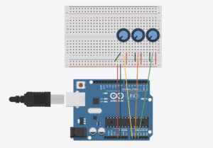
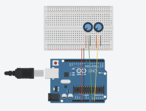
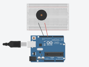
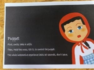
     First of all, we asked the fellows which sensor we can use to control the movement of the puppet directly. They suggested that we can use the accelerometer. The angle of the rise and fall of the puppet’s arms and legs would change with the angle that the user leans the cross. In addition, since it is hard to capture the users’ face when they are moving, Professor Eric suggested us to take a picture of the user at the beginning. He helped us with the coding and finally we made it like a process of asking them to take a selfie. I wrote a script and recorded my voice to be the puppet’s voice. The lines include, “What should I do?”, “What if they will be disappointed at me?”, “What if I cannot fit in?”. The last sentence is, “Hey friend, do you know, you are just like me.” After this last sentence, the image that the user’s face is in the head of the digital puppet will be shown to the user, so that we can show the logic that while we are controlling others, we are also being controlled. However, there were some problems with the Arduino part. The night before presentation, we were testing the accelerometer, hoping that everything could work well. However, we could not even find the port connected to the computer. Besides, in our previous testing, we found that the accelerometer is quite unstable and sensitive, making it hard to control the movement of the real puppet. Professor Marcela suggested us to change the accelerometer to tilt sensors, which are more stable. We took this advice and changed the code again. Tilt sensor functions as a button, if we lean it, a certain behavior could be triggered. In our case, we used two tilt sensors to control the movement of the arms and legs respectively. And the logic is, if the left arm rises up, the right arm would fall down, vice versa. Since tilt sensor only has a function as on or off, it is also easier for us to send the data to Processing. The digital image in Processing would change with the real puppet, following its poses. After we got everything done, I made a poster, on which I wrote the instructions and also the explanation of our project theme.

0

0

0

0

0

Conclusions

   Our project aligns well with my definition of interaction. In my preparatory research and analysis, I wrote my personal definition of a successful interaction experience. In my opinion, the process of interaction should be clear to the users, so that they can get a basic sense of what they should do to interact with the device. Various means of expression can be involved, such as visuals and audios. The experience could be thought-provoking, which may reflect the facts in the real life. My partner and I have created a small device as a game in our midterm project, so this time we decided to create an artistic one as a challenge. Our project aims at those who intentionally or compulsively cater to the social roles imposed on them by the forces in the society. We showed the logic that while we are controlling others while also being controlled by the others. In fact, it is hard to show a theme in an interactive artistic installation, and it was hard for us to find the delicate balance, the balance that we can trigger the thoughts of the user without making everything too heavy. The visual effect of our project is satisfying, and we also use music and voices to add more means of expression. The user’s interaction with our project is direct and clear. Instead of touching the cold buttons on the keyboard, they can hold the cross, listen to the monologue of the puppet, and thus build an invisible relation of empathy with the real puppet. After the final presentation, we have also received several precious suggestions. If we have more time, we would probably try to make the whole interactive process longer with more means of interaction, so that the user can be given more time to think more deeply about the theme. There are many ways to show our theme, but the results could be entirely different. We are given possibilities but may also get lost. The most important thing that I have learnt in this experience is to always be clear about what I am trying to convey and what the goals are at the beginning. Without a clear theme in mind, we are likely to lose directions, and the final work could be a mixture of various disordered ideas.

Video of the whole interactive experience:

Arduino Code:

#include <Servo.h>
Servo myservo1;
Servo myservo2;
Servo myservo3;
Servo myservo4;// create servo object to control a servo

int angleArm = 0;
int angleLeg = 0;
const int tiltPin1 = 2;
const int tiltPin2 = 4;
int tiltState1 = 0;
int tiltState2 = 0;

void setup() {
Serial.begin(9600);
myservo1.attach(3);
myservo2.attach(5);
myservo3.attach(6);
myservo4.attach(9);
pinMode(tiltPin1, INPUT);
pinMode(tiltPin2, INPUT);
}


void loop() {
//reasonable delay
delay(250);

tiltState1 = digitalRead(tiltPin1);
tiltState2 = digitalRead(tiltPin2);

if (tiltState1 == HIGH) {
angleArm = 90;
} else {
angleArm = -90;
}

if (tiltState2 == HIGH) {
angleLeg = 30;
} else {
angleLeg = -30;
}

// Serial.println(angleArm);
// Serial.println(angleLeg);

myservo1.write(90 + angleArm);
myservo2.write(90 - angleArm);
myservo3.write(90 + angleLeg);
myservo4.write(90 - angleLeg);

Serial.print(angleArm);
Serial.print(","); // put comma between sensor values
Serial.print(angleLeg);


Serial.println(); // add linefeed after sending the last sensor value
delay(100);
}


Processing Code

 
import processing.sound.*;
SoundFile sound;
SoundFile sound1;
import processing.video.*; 
Capture cam;
PImage cutout = new PImage(160, 190);
import processing.serial.*;
String myString = null;
Serial myPort;
int NUM_OF_VALUES = 2;   /** YOU MUST CHANGE THIS ACCORDING TO YOUR PROJECT **/
int[] sensorValues;      /** this array stores values from Arduino **/

PImage background;
PImage body;
PImage arml;
PImage armr;
PImage stringlr;
PImage stringar;
PImage stringal;
PImage legl;
PImage stringll;
PImage legr;
float yal=100;
float yll=0;
float yar=0;
float ylr=0;
float leftangle=PI/4;
float rightangle=-PI/4;
float leftleg = 570;
float rightleg = 570;
float armLerp = 0.22;
float legLerp = 0.22;
float pointleftx =-110;
float pointlefty =148;
PImage body2;
boolean playSound = true;
void setup() {
  size(850, 920);
  setupSerial();
  cam = new Capture(this, 640, 480);
  cam.start(); 
  background = loadImage("background.png");
  body=loadImage("body.png");
  arml=loadImage("arml.png");
  stringal=loadImage("stringal.png");
  armr=loadImage("armr.png");
  legl=loadImage("legl.png");
  stringll=loadImage("stringll.png");
  legr=loadImage("legr.png");
  stringar=loadImage("stringar.png");
  stringlr=loadImage("stringlr.png");
  body2 =loadImage("body2.png");
  sound = new SoundFile(this, "voice.mp3");
  sound1 = new SoundFile(this, "bgm.mp3");
  sound1.play();
  sound1.amp(0.3);  
}

void draw() {
  updateSerial();
  printArray(sensorValues);
  if (millis()<15000) {
    if (cam.available()) { 
      cam.read();
    } 
    imageMode(CENTER);

    int xOffset = 220;
    int yOffset = 40;

    for (int x=0; x<cutout.width; x++) {
      for (int y=0; y<cutout.height; y++) {
        color c = cam.get(x+xOffset, y+yOffset);
        cutout.set(x, y, c);
      }
    }
    background(0);
    image(cutout, width/2, height/2);
    fill(255);
    textSize(30);
    textAlign(CENTER);
    text("Place your face in the square", width/2, height-100);
    text(15 - (millis()/1000), width/2, height-50);
  } else { 
    if (!sound.isPlaying()) {
      // play the sound
      sound.play();
    } 
    imageMode(CORNER);
    image(background, 0, 0, width, height);
    image(legl, 325, leftleg, 140, 280);  
    image(legr, 435, rightleg, 85, 270);
    image(body, 0, 0, width, height);
    if (millis()<43000) {
      image(body, 0, 0, width, height);
    } else {
      image(cutout, 355, 95);
      image(body2, 0, 0, width, height);
 
      sound.amp(0);
    }
    arml();
    armr();
    //stringarmleft();
    image(stringal, 255, yal, 30, 470);
    image(stringll, 350, yll, 40, 600);
    image(stringar, 605, yar, 30, 475);
    image(stringlr, 475, ylr, 40, 600);
    int a = sensorValues[0];
    int b = sensorValues[1];
    float targetleftangle= PI/4 + radians(a/2);
     float targetrightangle= -PI/4 + radians(a/2);
     float targetleftleg= 570+b*1.6;
     float targetrightleg= 570-b*1.6;
     leftangle = lerp(leftangle, targetleftangle, armLerp);
     rightangle = lerp(rightangle, targetrightangle, armLerp);
     leftleg = lerp(leftleg, targetleftleg, legLerp);
     rightleg = lerp(rightleg, targetrightleg, legLerp);
     
float targetpointr = -100-a*1.1;
float targetpointl = -120+a*1.1;
float targetpointr1 = -50+b*1.3;
float targetpointr2 = -50-b*1.3;
yal= lerp(yal, targetpointr, armLerp);
yar = lerp(yar,targetpointl,armLerp);
yll= lerp(yll,targetpointr1,legLerp);
ylr = lerp(ylr,targetpointr2,legLerp);
  }
}

void arml() {
  pushMatrix();
  translate(375, 342);
  rotate(leftangle);
  image(arml, -145, -42, 190, 230);
  fill(255, 0, 0);
  noStroke();
  popMatrix();
}


void armr() {
  pushMatrix();
  translate(490, 345);
  rotate(rightangle);
  image(armr, -18, -30, 190, 200); 
  popMatrix();
}

void setupSerial() {
  printArray(Serial.list());
  myPort = new Serial(this, Serial.list()[ 11 ], 9600);
  myPort.clear();
  myString = myPort.readStringUntil( 10 );  // 10 = '\n'  Linefeed in ASCII
  myString = null;

  sensorValues = new int[NUM_OF_VALUES];
}

void updateSerial() {
  while (myPort.available() > 0) {
    myString = myPort.readStringUntil( 10 ); // 10 = '\n'  Linefeed in ASCII
    if (myString != null) {
      String[] serialInArray = split(trim(myString), ",");
      if (serialInArray.length == NUM_OF_VALUES) {
        for (int i=0; i<serialInArray.length; i++) {
          sensorValues[i] = int(serialInArray[i]);
        }
      }
    }
  }
}

Recitation 10: Object Oriented Programming Workshop —— Leah Bian

 For this recitation, we first had a quick workshop about the map() function. I reviewed when to use this function, and what the formats are. After this workshop finished, we were asked to choose a workshop to attend. The choices included media manipulation, serial communication, and object oriented programming. In our final project, we will focus on how to send data between Arduino and Processing, and how to draw and control the image of the marionette in Processing. Therefore, my partner attended the workshop about serial communication, and I chose the workshop about object oriented programming.

   In the workshop, Tristan gave us a detailed explanation about what “object” means, and what the parts of it are, which include class and instance. We thus went over the process of writing codes of object oriented programming from bigger parts (class, instance) to the smaller ones (variables, constructor, functions). Using the emoji faces as example, we started to work on the code together. Based on the code that we wrote during recitation, I started to create my own animation as exercise.

We needed to use classes and objects, and the animation should include some level of interactivity. As requirements, we needed to use the map() function and an ArrayList. I decided to use the mousePressed function as way of interaction. The shapes would be created at the mouse’s position. After searching a basic function for a star online, I modified the code to meet the requirement of using arrays. Creating a star needs to use the vertex() function for ten times. I let the stars to fall down to the bottom of the screen by setting the yspeed to random(3,7). I wrote a bounce function, so that if the stars hit the boundaries on the left and the right they will turn to the opposite direction. Finally, I used the map() function to limit the area where the stars can be created.

These are my codes in Processing ( 2 parts):

ArrayList<Stars> stars = new ArrayList<Stars>();

void setup() {
  size(800, 600);
  noStroke();
}

void draw() {
  background(130,80,180);
  for (int i=0; i<stars.size(); i++) {
    Stars s = stars.get(i); 
    s.move();
    s.bounce();
    s.display();
  }
  float x=map(mouseX,0,width,width/6,width-width/6);
  float y=map(mouseY,0,height,height/6,height-height/6);
  if (mousePressed==true) {
    stars.add( new Stars(x,y));
  }
}

class Stars {
  float x, y, size;
  color clr;
  float xspeed, yspeed;

  Stars(float tempX, float tempY) {
    x = tempX;
    y = tempY;
    size = random(10, 100);
    clr = color(255, random(180,255), random(50,255));
    xspeed = random(-3, 3);
    yspeed = random(3, 7);
  }

  void display() {
    fill(clr);
   beginShape();
   vertex(x,y);
   vertex(x+14,y+30);
   vertex(x+47,y+35);
   vertex(x+23,y+57);
   vertex(x+29,y+90);
   vertex(x,y+75);
   vertex(x-29,y+90);
   vertex(x-23,y+57);
   vertex(x-47,y+35);
   vertex(x-14,y+30);
    endShape(CLOSE);
  }

  void move() {
    x += xspeed;
    y += yspeed;
  }

  void bounce() {
    if (x < 0) {
      xspeed = -xspeed;
    } else if (x > width) {
      xspeed = -xspeed;
    }
}
}

Recitation 9: Media Controller——Leah Bian

For this week’s recitation, I created a Processing sketch to control the movement, size and color of an image. Data from Arduino are sent to Processing, which thus decides the image’s attributes. I used three potentiometers to adjust the analog values, and used the “serial communication” sample code as the basis for further modifications.

It was not hard to build the circuit, since we use potentiometers quite often. After finishing the circuit, I started to write the code. I adjusted the “Serial. print()” and “Serial. Println()” functions to send the data from Arduino to Processing smoothly. I chose an image from the famous cartoon “Rick and Morty” as my media. I decided to let the three potentiometers control the movement, size and color of the image respectively. I used the “map()” function to limit the analog values. It was not difficult to write the code for changing the image’s size and position, but changing colors was a bit complicated. I chose colorMode(RGB) to set the image with various colors, instead of only with white, grey and black. I used the “tint()” function to set the color. But since I only have one potentiometer controlling the color of the image, I can only set the image with analogous color schemes.

0
diagram

This is my code for Processing:

import processing.serial.*;

String myString = null;
Serial myPort;
PImage img;
int NUM_OF_VALUES = 3;   
int[] sensorValues;  

void setup() {
  size(800, 800);
  img = loadImage("rickk.png");
  setupSerial();
  colorMode(RGB);
}

void draw() {
  background(0);
  updateSerial();
  printArray(sensorValues);
  float a = map(sensorValues[0],0,1023,0,800);
  float b = map(sensorValues[1],0,1023,0,255);
  float c = map(sensorValues[2],0,1023,400,800);
  tint(b, 30, 255);
  image(img,a,200,c,c);
}

void setupSerial() {
  printArray(Serial.list());
  myPort = new Serial(this, Serial.list()[5], 9600);
  myPort.clear();
  myString = myPort.readStringUntil( 10 ); 
  myString = null;
  sensorValues = new int[NUM_OF_VALUES];
}

void updateSerial() {
  while (myPort.available() > 0) {
    myString = myPort.readStringUntil( 10 ); 
    if (myString != null) {
      String[] serialInArray = split(trim(myString), ",");
      if (serialInArray.length == NUM_OF_VALUES) {
        for (int i=0; i<serialInArray.length; i++) {
          sensorValues[i] = int(serialInArray[i]);
        }
      }
    }
  }
}

This is my code for Arduino:

void setup() {
Serial.begin(9600);
}

void loop() {
int sensor1 = analogRead(A0);
int sensor2 = analogRead(A1);
int sensor3 = analogRead(A2);
Serial.print(sensor1);
Serial.print(“,”);
Serial.print(sensor2);
Serial.print(“,”);
Serial.print(sensor3);
Serial.println ();
delay(100);
}

Reflection:

This week’s reading, Computer Vision for Artists and Designers, inspired me a lot. According to the article, Myron Krueger, the creator of Videoplace, firmly believed that the entire human body should have a role in people’s interactions with computers. In my previous definition of an interactive experience, I also mention this idea. Videoplace, an installation that captured the movement of the user, makes my hypothesis concrete and clear. In the project that I made for this recitation, the user can interact with the device only with the potentiometers, which makes the interactivity here quite low. Besides, the whole process is too simple and it does not convey any meaning implications, compared with the other art works mentioned in the reading, such as LimboTimeand Suicide Box. In conclusion, an interactive experience should let the user fully engaged, probably by physical interaction and building up a meaningful theme. The project that I made this time is not highly interactive due to various limitations, but I will try to create a satisfying interactive experience for the final project.

Reference:

Computer Vision for Artists and Designers: 

https://drive.google.com/file/d/1NpAO6atCGHfNgBcXrtkCrbLnzkg2aw48/view

Final Project Essay—— Leah Bian

Project Title: Puppet

In “The Future of Design: When you come to a fork in the road, take it”, the author discusses the significance of human-centered design. It requires a deep understanding of people and involves careful observations and analyses to determine needs. When working on the project proposal, I applied the main concept of human-centered design to our project. We first came up with the theme of puppet, which always represents those who are controlled and follow commands. We further developed the theme by extending it to the concept of social image. Based on this theme, we developed our design by thinking about how we can utilize Arduino and Processing to express this idea. We found that the Arduino servo is a perfect choice to control the movement of the marionette, and Processing can be used for the interaction, letting the user control the marionette in an indirect way. We then came up with our further plan and recorded it in the proposal. A miniature stage with stage curtains and lighting will be set, on which we will place a marionette. The marionette will be connected to the Arduino servos on the roof with strings, so that it can change poses. On the wall behind the miniature stage, we will cast the Processing image with a projector. In Processing, we will draw the shadow of the puppet. The users can control the moveable joints of the puppet by the mouse. Data of these gestures would be passed from Processing to Arduino. The real marionette on the stage would first quickly and randomly change a series of postures, and finally end up with the pose set by the user in Processing before. In addition, we will try to enhance the artistic appeal of the installation with music, lighting and so on. The potential challenges include how to accurately pass the data of the puppet’s poses from Processing to Arduino; how to connect servos with the puppet smoothly with the correct mechanism; and how we can convey the heavy topic in an implicit way.

After submitting the proposal, we made a plan to make our tasks clear. From Nov. 21 to Nov. 24, we will first collect general information. We will get a marionette to figure out how the mechanism works and how we can modify it to connect it with servos. In addition, we will make final decisions about how the image in Processing will look like to convey our theme; what else we can do to add aesthetic values; what the materials that may involve are… We will draw a draft of the final work as well. From Nov. 24 to Nov. 30, we will get the code done. During that week, we will also start to prepare the materials (start to do 3D printing). If necessary, we will make some modifications to the original plan. From Dec.1 to Dec. 10, we will assemble all the materials together and add some detailed decorations to enhance the aesthetic values, such as lighting, music, background settings and so on. We will invite some peers and IMA fellows to test our project, and collect suggestions from them to make final modifications.

In my preparatory research and analysis, I wrote my personal definition of a successful interaction experience. In my opinion, the process of interaction should be clear to the users, so that they can get a basic sense of what they should do to interact with the device. Various means of expression can be involved, such as visuals and audios. The experience could be thought-provoking, which may reflect the facts in the real life. Our project aligns with my definition of interaction well. It aims at those who intentionally or compulsively cater to the social roles imposed on them by the forces in the society. The user plays the role of the forces that decide our social images, while the puppet on the stage represents ourselves, who are constrained by the social expectations. The “struggle” that the puppet has before it stops with its final pose represents our mental struggles when pondering whether to meet social expectations. However, we ultimately make the passive or initiative choice that satisfies the forces just as what the puppet does. We expect that the user can be inspired by this artistic installation, gain new thoughts, or have reflection. The marionette on stage may be clownish, but it is more than that. We hope that we can find the balance between entertainment and artistic expression, and finally convey our theme to the audience.

Reference: 

“The Future of Design: When you come to a fork in the road, take it”:

https://jnd.org/the_future_of_design_when_you_come_to_a_fork_in_the_road_take_it/

Recitation 8: Serial Communication——Leah Bian

Exercise 1: Make a Processing Etch A Sketch

Step 1: For this exercise, I needed to send two analog values from Arduino to Processing via serial communication. In Processing, I drew an ellipse, and its location was defined by the values from Arduino. I built a circuit with two potentiometers, controlling the ellipse’s x-axis and y-axis movement respectively. I used the A to P (multipleValues) code example and made some modifications. For example, I changed the number of the analog values in Processing, and used map function to limit the range. The interaction here is clear but quite simple, but it can be a single part of a bigger interactive process. 

exercise 1
exercise 1

Code (Processing):

import processing.serial.*;
String myString = null;
Serial myPort;
int NUM_OF_VALUES = 2;   /** YOU MUST CHANGE THIS ACCORDING TO YOUR PROJECT **/
int[] sensorValues;      /** this array stores values from Arduino **/

void setup() {
  size(500, 500);
  setupSerial();
}

void draw() {
  background(0);
  updateSerial();
  float x = map(sensorValues[0],0,1023,0,500);
  float y = map(sensorValues[0],0,1023,0,500);
  printArray(sensorValues);
  fill(255);
  ellipse(x,y,100,100);
}

void setupSerial() {
  printArray(Serial.list());
  myPort = new Serial(this, Serial.list()[5], 9600);
  
  myPort.clear();
  // Throw out the first reading,
  // in case we started reading in the middle of a string from the sender.
  myString = myPort.readStringUntil( 10 );  // 10 = '\n'  Linefeed in ASCII
  myString = null;

  sensorValues = new int[NUM_OF_VALUES];
}

void updateSerial() {
  while (myPort.available() > 0) {
    myString = myPort.readStringUntil( 10 ); // 10 = '\n'  Linefeed in ASCII
    if (myString != null) {
      String[] serialInArray = split(trim(myString), ",");
      if (serialInArray.length == NUM_OF_VALUES) {
        for (int i=0; i<serialInArray.length; i++) {
          sensorValues[i] = int(serialInArray[i]);
        }
      }
    }
  }
}

Code (Arduino):

void setup() {
Serial.begin(9600);
}

void loop() {
int sensor1 = analogRead(A0);
int sensor2 = analogRead(A1);

// keep this format
Serial.print(sensor1);
Serial.print(“,”); // put comma between sensor values
Serial.print(sensor2);
Serial.println ();
// too fast communication might cause some latency in Processing
// this delay resolves the issue.
delay(100);
}

Step 2: For step 2, I modified the code to draw a line. I needed to keep track of the previous x and y values to draw a line from there to the new x and y positions. Therefore, I used float() function for four times to define the variables, and then drew the line.

Code (Processing):

import processing.serial.*;
String myString = null;
Serial myPort;
int NUM_OF_VALUES = 2;   /** YOU MUST CHANGE THIS ACCORDING TO YOUR PROJECT **/
int[] sensorValues;      /** this array stores values from Arduino **/

void setup() {
  size(500, 500);
  background(0);
  setupSerial();
}

void draw() {
  float pX = map(sensorValues[0], 0, 1023, 0, width);
  float pY = map(sensorValues[1], 0, 1023, 0, width);
  updateSerial();
  float x = map(sensorValues[0], 0, 1023, 0, width);
  float y = map(sensorValues[1], 0, 1023, 0, height);
  printArray(sensorValues);
  stroke(255);
  line(pX,pY,x,y);
}

void setupSerial() {
  printArray(Serial.list());
  myPort = new Serial(this, Serial.list()[5], 9600);
  
  myPort.clear();
  // Throw out the first reading,
  // in case we started reading in the middle of a string from the sender.
  myString = myPort.readStringUntil( 10 );  // 10 = '\n'  Linefeed in ASCII
  myString = null;

  sensorValues = new int[NUM_OF_VALUES];
}

void updateSerial() {
  while (myPort.available() > 0) {
    myString = myPort.readStringUntil( 10 ); // 10 = '\n'  Linefeed in ASCII
    if (myString != null) {
      String[] serialInArray = split(trim(myString), ",");
      if (serialInArray.length == NUM_OF_VALUES) {
        for (int i=0; i<serialInArray.length; i++) {
          sensorValues[i] = int(serialInArray[i]);
        }
      }
    }
  }
}

Code (Arduino):

void setup() {
Serial.begin(9600);
}

void loop() {
int sensor1 = analogRead(A0);
int sensor2 = analogRead(A1);

// keep this format
Serial.print(sensor1);
Serial.print(“,”); // put comma between sensor values
Serial.print(sensor2);
Serial.println ();
// too fast communication might cause some latency in Processing
// this delay resolves the issue.
delay(100);
}

Exercise 2:Make a musical instrument with Arduino

For this exercise, I wrote a Processing sketch that sends values to Arduino based on the mouse’s x and y positions. A hint was provided that we should use the tone() function, so I studied it first. The syntax of the function should be “tone(pin, frequency, duration)”, and the function can only be used with pin3 and pin11. Therefore, I put a buzzer on the breadboard and connected it to pin11 and the ground. The serial values from Processing are sent to Arduino and are translated into frequency and duration for a tone, which will be sounded by the buzzer. Besides, I drew an ellipse to make the location of the mouse’s x and y positions clearer. The interaction here is clear but simple, since only two variables are involved and what the user needs to do is just to move the mouse. However, this simple musical instrument could be a basis for further development and the idea can be an interesting inspiration.

0
exercise 2

Code (Processing):

import processing.serial.*;
int NUM_OF_VALUES = 2;  /** YOU MUST CHANGE THIS ACCORDING TO YOUR PROJECT **/
Serial myPort;
String myString;
int values[] = new int[NUM_OF_VALUES];

void setup() {
  size(500, 500);
  background(0);

  printArray(Serial.list());
  myPort = new Serial(this, Serial.list()[5], 9600);
 
  myPort.clear();
  myString = myPort.readStringUntil( 10 );  // 10 = '\n'  Linefeed in ASCII
  myString = null;
}

void draw() {
  background(0);
  values[0]=mouseX;
  values[1]=mouseY;
  circle(mouseX,mouseY,80);
  sendSerialData();
  echoSerialData(200);
}

void sendSerialData() {
  String data = "";
  for (int i=0; i<values.length; i++) {
    data += values[i];
    if (i < values.length-1) {
      data += ","; // add splitter character "," between each values element
    } 
    else {
      data += "n"; // add the end of data character "n"
    }
  }
  myPort.write(data);
}

void echoSerialData(int frequency) {
  if (frameCount % frequency == 0) myPort.write('e');

  String incomingBytes = "";
  while (myPort.available() > 0) {
    incomingBytes += char(myPort.read());
  }
  print( incomingBytes );
}

Code (Arduino):

#define NUM_OF_VALUES 2

int tempValue = 0;
int valueIndex = 0;
int values[NUM_OF_VALUES];

void setup() {
Serial.begin(9600);
pinMode(11, OUTPUT);
}

void loop() {
getSerialData();
tone(11,values[0],values[1]);

}

//recieve serial data from Processing
void getSerialData() {
if (Serial.available()) {
char c = Serial.read();
switch (c) {
case ‘0’…’9′:
tempValue = tempValue * 10 + c – ‘0’;
break;
case ‘,’:
values[valueIndex] = tempValue;
tempValue = 0;
valueIndex++;
break;
case ‘n’:
values[valueIndex] = tempValue;
tempValue = 0;
valueIndex = 0;
break;
case ‘e’: // to echo
for (int i = 0; i < NUM_OF_VALUES; i++) {
Serial.print(values[i]);
if (i < NUM_OF_VALUES – 1) {
Serial.print(‘,’);
}
else {
Serial.println();
}
}
break;
}
}
}