Materials:
- 1- stepper motor
- 1- ic chip
- 1-power jack
- 1-12 VDC power supply
- 1-Arduino kit and its contents
- 2 -Laser-cut short arms
- 2-Laser-cut long arms
- 1-Laser-cut motor holder
- 2-3D printed motor coupling
- 5-Paper Fasteners
- Pen
- Paper
Step 1: Build the Circuit
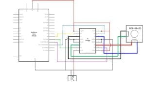
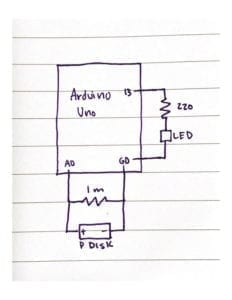
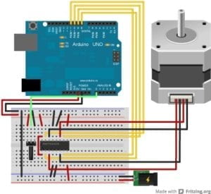
Circuit Schematic
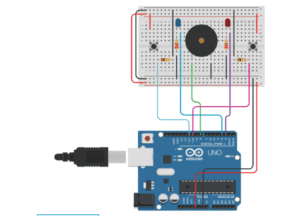
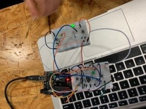
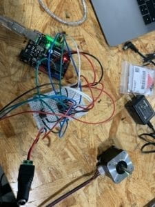
Circuit in Action
Using the schematic provided on the recitation exercise instructions, I carefully connected all the wires to the breadboard in their correct places. I double checked my connections twice to make sure the 12 volt power supply wasn’t connected to my computer in any way, I didn’t want to fry my new computer. After checking to make sure all my wiring was correct, I connected my Arduino to my computer and uploaded the code. At this point I hadn’t plugged in the 12 volt power source yet, but the stepper motor started to move with just the power provided from the Arduino. I was surprised and at first thought I did something wrong. I consulted one of the fellows for assurance I hadn’t wired something wrong and was hurting my computer was the stepper motor continued to move. Thankfully it wasn’t doing any damage so I continued onto the next step without using the 12 volt power source.
Step 2: Add Potentiometer
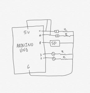
Circuit with Potentiometer Schematic
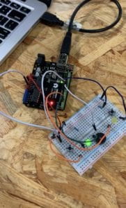
Circuit with Potentiometer
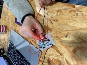
Stepper Motor with Potentiometer
I found following the Tinkercad schematic from Arduino’s site was helpful in figuring out how to connect the potentiometer. After I connected the potentiometer to the circuit, I opened the new code in Arduino, changed the number of steps to 200, and uploaded that code to the Arduino. I was confused on why the stepper motor wasn’t following the potentiometers movements and asked my partner if she was having a similar issue. We then came to to conclusion I had simply forgotten to add the map() function to my code. Once that was put in place, the circuit worked as planned.
Step 3: Build a Drawing Machine
Drawing Machine
Putting the drawing machine together was easier than building the circuits needed to make it work. We weren’t met with any big issues, other than putting one of the drawing hands on backwards at first that we quickly noticed and fixed. Our drawing didn’t really end up looking like anything, nonetheless it was able to draw some squiggly oval shapes pretty decently.
Question 1:
I would love to build a device that would help me organize my clothes. I have a tendency to organize it all once and then it ends up a mess of shirts and jackets that is impossible to find anything in. It’d be a device you could instal in your closet that could be set up to organize your hangers in a certain way, by color or type of clothing. All you’d have to do is put the piece of clothing on a hanger and it’d do the rest. An actuator could be used to move the “hanger hand” back and forth across the closet when reorganizing the clothes.
Question 2:
After looking at The Giant Painting Machine by Douglas Irving Repetto, I noticed how similar it was to our very simple small drawing machine. Both create abstract art and art controlled by mechanical elements that are responsible for the creation of the art piece. But Repetto’s device is significantly more refined and interesting to watch in action. The actuators used for his project were also probably chosen to be able to use a wider range of movement and use a higher level of precision when moving as well. Im sure if our drawing machine had components like that, the drawings it made would be more pleasing to look at.