Group Project Reflection by Megan Rhoades

Interaction is a process in which two or more actors use a shared language (or method of input) to recognize and react to each other. This definition of interaction is based on the one given on page four of Crawford’s “What Exactly is Interactivity?.” However, I have changed it slightly to include the idea of a shared language. This concept is based on page 19 of Igoe and O’Sullivan’s “Introduction to Physical Computing,” in which the authors include an image of how a computer “sees” us. I believe this concept is important to recognize because how a computer interacts with our bodies is a key part of successful interaction. One additional concept I would like to mention is the idea of interactivity lying on a spectrum, as Crawford’s “What Exactly is Interactivity” proposes. The more recognition that occurs between the user and device, the more interactive the device feels.

One project that I believe does not fully satisfy this definition of interaction is the “Terra Mars” project by SHI Weili. This project uses AI to map the Earth over the terrain of Mars. This AI is advanced, but does not truly communicate with humans. Rather, it simply translates information into a complete image of a planet. Although humans can toggle the map’s features, the two do not operate on a shared scale or “language” (in this case, the user and project do not interact based on the human’s senses, but rather only through the device’s controls).

https://www.creativeapplications.net/environment/terra-mars-anns-topography-of-mars-in-the-visual-style-of-earth/

One project that I believe comes closer to this definition of interactivity is Hayeon Hwang’s “Expressive Tactile Controls.” This project features communication between a user and a series of switches. Depending on the switch, the different states of the user get a certain response (for example, the “Impatient” button needs only the slightest touch to be triggered. The variety of reactions the user and switches can create fits the idea of recognizing/reacting that characterizes interactivity.

https://www.creativeapplications.net/member-submissions/expressive-tactile-controls/

Our project, the Dreamcatcher, is based on this idea of interaction. On the Dreamcatcher’s end, the device recognizes images coming from the user and knits the information together into a complete dream that the user can then peruse. The element of the project that I believe best exemplifies its interactive capability is the Dreamcatcher’s ability to expand dreams into a full narrative based on the user’s likes and dislikes. In this way, the more the Dreamcatcher learns about its user, the more it can cater its output to the user’s individual desires. For this definition of interactivity, more mutual recognition (“shared” language) occurring between a device and its user means the interactive capability is stronger.
Recitation 3: By Megan Rhoades

Recitation 3: Sensors (Moisture sensor)

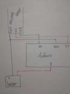
Diagram: 

recitation3diagram_meganrhoades

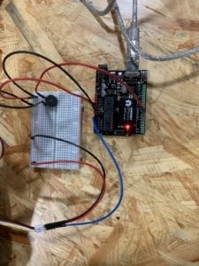
The circuit:

recitation3_rhoades

Components:

  • Arduino
  • USB
  • Breadboard
  • Jumper cables
  • Moisture sensor
  • Buzzer

Process:

My partner and I had two different kinds of issues in building this circuit:

  1. Circuit issues: In terms of the circuit-building, we had some confusion about the yellow and white wires of the moisture sensor. We also had a moment of confusion about connecting the buzzer, as we had plugged it into the wrong port. These were not big issues, though. Most importantly, after this recitation I have a better idea of how to read schematics and view my own circuits.
  2. Coding issues: We had a lot of trouble with the coding. Figuring out how to make the sensor read was actually quite easy, as was making the buzzer sound in response to the sensor. This was too simple, so we decided we wanted the buzzer to play a melody instead of just sounding off — we had trouble making this happen. We took code from the “toneMelody” sample, but had several issues fitting it in: we forgot to add the tab which defined the tones, forgot to replace the port in the original code with the correct port for our buzzer, and forgot which parts of the code needed to go in the looped section.  After a lot of trial and error we found a way to make the code work. 

Questions:

1. We intended to assemble a circuit which would play a small melody after sensing an increase in moisture. I can see this kind of circuit being used in lots of different ways. The most obvious example to me would be using this in a weather-related context, or with a humidifier which alerts its user when a certain humidity is reached.

2. This recitation definitely showed me how code can be like a recipe. Code is a set of instructions that will be followed exactly, like strictly following a recipe. What really sticks with me is the fact that combining different kinds of code is like combining two recipes — rather than simply following one and then following the other, the two must be fit together to form an amalgamated product.

3. The development of computer technology and new media seems to have an effect on how we understand our tools. Rather than working with hands-on items, the tools we use in our daily life are becoming more and more removed from our own ways of understanding. We don’t speak the same “language” as our technology anymore . Basically, we find ways to interact with things which do not seem natural to us (and which many of us do not fully understand).

Recitation 2: By Megan Rhoades

Circuit 1: Fade

Circuit 1 Fade: Diagram

Components: 

  1. Breadboard: site to make connections between components
  2. LED: glows with flow of current
  3. Aduino Uno: processes code, acts as source of current
  4. USB Cable: connects arduino to computer
  5. Jumper cables: allows current to flow
  6. 220 Ohm Resistor: controls flow of current to LED

Process: 

My partner and I completed this circuit fairly easily. Building circuits has gotten much easier since the first recitation, and finding the sample code to run for the fade did not take much time either. 

Circuit 2: toneMelody

circuit2_tonemelody: diagram

Components:

  1. Speaker/Buzzer: creates sound with flow of current

Process:

While the building of the circuit was fairly easy (even more simple than the first circuit with the elimination of a resistor!), the coding gave us some minor trouble in this circuit. We found the sample code for toneMelody fine, but the inclusion of the file to save the “pitches” in gave us some confusion, as we thought we would have to redo a file that was already included in the code. After figuring this out, the circuit worked fine. 

Circuit 3: Speed Game

speed circuit diagram

Components:

  1. 220 Ohm Resistor: controls flow of current
  2. 10K Ohm Resistor: controls flow of current
  3. Multimeter: Used to measure and discriminate between resistors
  4. Switch/button: When pressed, completes circuit and allows current to flow
  5. LED: lights when current flows through it

Process:

Building this circuit was actually quite fun. I enjoyed carefully measuring out how much space each element could take, as well as tinkering with new (and more efficient) ways to distinguish between ground and power. We did have some difficulty where it seemed that only one button was working, but this was not due to the setup of the circuit but rather that one of the resistors was simply not pushed in enough. 

The code gave us some minor trouble in that we could not figure out how to actually play the game until it was pointed out to us that the game would register in the analog section of the arduino program. We also had to figure out where the button was which would reset the code, allowing us to play again. After these bugs were figured out we could play with no problem. 

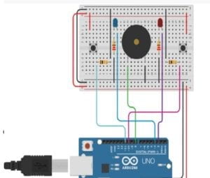
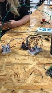
Optional Circuit 4: Four-Player

We had only a small amount of time left, but we still gave this circuit a go. We were not successful…rather than adjusting the setup of the two breadboards and removing parts (for example using only one buzzer or having buttons separate from the lights), we decided to simply use longer cables to connect each breadboard to ground, power, and the arduino port.

We also had some trouble getting the code together: there was some confusion about labeling each component (the switches and LEDs) with the correct number and port. Regardless of whether we had managed to complete our circuit correctly, I believe the coding would have given us more troubles.

The final product is a bit of a half-complete mess and looks quite odd (very much the “spaghetti” look), but I think for the small amount of time it was an interesting attempt:

circuit4_attempt_MeganRhoades

Final Questions:

Question 1: The reading about physical computing has left me with thoughts about the different buffers between humans and the technology we use in our daily lives. In the circuits we built in recitation, it feels very hands-on to use them and has a sense of being built from the ground-up. However, much of the technology we use in our daily lives has more computing and levels of abstraction to them. It makes me wonder about the amount of computing that goes into, say, an elevator. 

Question 2: If I had 100,000 LEDs I would definitely want to make a glowing floor of some kind — I am aware that this is a somewhat weird answer, but I love the idea  of light coming from a place that we do not normal see it coming from. Most lights, after all, are mounted at our eye-level and above. Maybe a sort of floor that glows as you walk along it, or changes color with the temperature of the room (not a very useful idea, maybe, but definitely something I would want to see!).

Recitation 1 (Megan Rhoades)

Circuit 1: Door Bell

Parts: 

  • Breadboard: Provides a base for the connections in a circuit
  • LM7805 Voltage regulator: Controls voltage, allowing for consistent output
  • Switch: When pressed, connects the circuit to allow power to reach the speaker
  • Speaker: Vibrates, creating a sound, with the introduction of electric current
  • Jumper cables: Provide connections for the circuit
  • Barrel jack: Connects power supply to outlet
  • 100 nF (0.1uF) Capacitor: Stores (and helps regulate) electric energy
  • 12 Volt Power Supply: Provides power source

Process:

  • While this was the simplest circuit, we had to acclimate to using the components and building circuits. The biggest challenge for us in this aspect was figuring out the difference between the power and the ground, especially when connecting the voltage regulator. Finishing the circuit also provided some difficulty, as we were initially unsure of how power was flowing to the ground from the buzzer and switch. Moving on in the class, I know that I will have to put more effort into distinguishing which wires should be ground. Despite this confusion, we finished this circuit fairly quickly after getting used to the components. 

Circuit 2: Lamp

Parts: 

  • 220 ohm Resistor: Reduces current flow
  • LED: Emits light with electric current
  • Multimeter: Used to measure resistance

Process:

  • The most difficult process in this circuit was learning to measure the resistor with the multimeter. Since our fingers effect the reading of the multimeter, we asked for advice and found that measuring the resistor in between our fingers gave an accurate reading. After finding the correct resistor we simply made small adjustments to our previous circuit in order to add the LED and the resistor.

Circuit 3: Dimmable Lamp

Parts:

  • 10K ohm Variable Resistor (Potentiometer): Allows for interaction, with a turn of the dial adjusting the strength of the electric current

Process:

  • This circuit was the easiest of the three. After adjusting the position of the light, we simply added the variable resistor. I did feel that I learned something from observing the interactivity of the resistor — this technology is basic yet I had never put thought into how it works. For that reason, this circuit was the most interesting to us. 

Push-Button Switch

Process:

  • After finishing circuit 3, my partner and I disassembled our circuit. For this reason, we had to reassemble the circuit for the inclusion of the new button. We had some difficulty with this new circuit. Again, we found ourselves confused with the difference between ground and power. We also found ourselves debating ways in which we could cut down on the number of jumper cables, simplifying our circuit. Although we had some difficulty we did eventually create a new circuit and I found the process useful in practicing the building process.

Question One

The interactivity reading introduced the idea that interactivity comes on a spectrum. This felt very clear to me thinking on the different circuits we built in recitation. The third circuit, which included a dimmable light, felt more interactive than those which had only a switch. Although all required action from a human (the press of the switch) to operate, this circuit was more responsive, giving not only the option of on/off but also the ability to control how much light was emitted. 

Question Two

As someone who is very interested in music, there are many interesting interactive possibilities. One idea that I have seen in an exhibit in my hometown in Ohio is an orchestra made of “electric instruments” — one example being a harp which sensed the movement of a human finger in a certain place and played the correct tone in response. I think this idea could be developed to help disabled musicians, similar to the EyeWriter being used to allow a disabled graffiti artist do his work. These examples which combine human creativity and electronic tools are especially interesting to me.