Recitation 4: Drawing Machines by Min Jee (Lisa) Moon

Materials:

For Steps 1 and 2

1 * 42STH33-0404AC stepper motor
1 * L293D ic chip
1 * power jack
1 * 12 VDC power supply
1 * Arduino kit and its contents

Step 1: Build the circuit

For this circuit, I, just following the circuit diagram from the recitation website. 
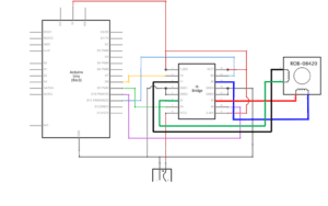
Above is a circuit diagram of the step one circuit.  Using this code (Please check the Rec4.1.ino) which I got from the Arduino example codes, I was able to create a working, one revolution of the stepper motor. The demonstration of the circuit 1 can be seen below in the video. 

Step 2: Control rotation with a potentiometer

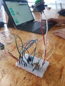
Above is a circuit diagram of the step two circuit.  Using this code (Please check the Rec4.2.ino) which I got from the Arduino example codes, I was able to create a working motor that was going around as I was turning the potentiometer. The demonstration can be found below. 

Step 3: Build a Drawing Machine!

For this, I partnered up with my partner. We first walked up and got our materials (listed below). 

Materials

2 * Laser-cut short arms
2 * Laser-cut long arms
1* Laser-cut motor holder
2 * 3D printed motor coupling
5 * Paper Fasteners
1 * Pen that fits the laser-cut mechanisms
Paper

Using the materials listed above, we just had two breadboards with the same circuit (because we have the same circuit from step 2). 

Below is the demo video of each of us turning the potentiometer. 

Documentation:

Question 1: What kind of machines would you be interested in building? Add a reflection about the use of actuators, the digital manipulation of art, and the creative process to your blog post.

I would love to build a machine that helps out people’s life. For example, I would like to have my food to be delivered to me, so that I can eat in my room. In addition, it is always a hassle to take a shower when I am only half awake. Therefore, I think it would be good for me if the machine is eligible for washing my body (including my face and teeth) without hurting me. Using the actuator, the machine would be able to adjust the amount of force to put to do the job gently enough. 

Especially, the artistic part would come in with doing my hair part. It would have to set a design, which the user can also input into the machine to make it do their daily hairstyles, and control the actuator to put enough force to do a specific job. 

Question 2: Choose an art installation mentioned in the reading ART + Science NOW, Stephen Wilson (Kinetics chapter). Post your thoughts about it and make a comparison with the work you did during this recitation. How do you think that the artist selected those specific actuators for his project?

Since I have enjoyed the movie Aladdin so much, the Flying Carpet built by David Moises left me with a deep impression. Though this piece lacks in terms of the artistic design and the comforts (because the user may have to stand on the carpet. However, I believe just by actualizing the flying carpet that is mentioned in the Aladdin did enough job because it would be a dream come true for most people (assuming everybody knows of Aladdin). 

Comparing this with our drawing machine, I know that our project is merely touching the basis of the actuator because we can not really tell which way the drawing machine is going to move as we are moving the potentiometer (it is not obvious enough — not interactive enough). 

The artist definitely would have had a hard time picking the type of actuator because the actuator has to do enough job to lift off a human being from the floor, it would have to be safe for them to ride the carpet, etc. He might have had used the actuator which can produce strong power (which would have to be strong enough but not too strong to lift off too much for safety purposes ).
Group Research Project: Interactive Future Device by Min Jee (Lisa) Moon

Definition

Interaction is a word that has been steadily used in our daily lives. Interaction broadly would be a term used for any process of communication happening between a person/thing and person/thing in a given environment. To dig deeper into this vocab word, we must recall what was mentioned by Crawford. According to Crawford, in order for a person or a thing to interact with another, one must go through the iterating process of input, processing, and output (1). Oddly it might sound since input and output are often used in the computer world, us listening what the professor says, what we see with our eyes, all can be counted as inputs. Similarly, us replying to the professor’s question, us high-fiving our friends all can be counted as outputs. 

If we were to recall our memory about what we read in Igoe and O’Sullivan’s “Introduction to Physical Computing”, we can understand the similarity between interaction with and without the computer’s involvement. He mentions, “computers for the rest of you”. From some point in our lifetime, we have been living amongst computers. Computers appeared everywhere. Technology no longer was a property of experts: the commoners could also easily use and access it. 

Like this, we are interacting without consciousness. Therefore, I believe, adding on to my previous definition of interaction from my previous documents, I believe an interactive project has to be a project that the user can easily figure out the usage (how to use the device), and the device must show a clear sign of processing based on the input that the user has put in. 

In such a way, this camera technology from this project fits well with my definition. If we were to remember the used-to-be-famous Pokemon Go, we tended to look around the world in the camera and threw pokemon balls. Just by giving the user this camera, drawing upon a lot of camera-related applications from animes and movies, when the user takes a look at the camera, it is likely that they will be curious to go around looking at the world through this project. Although the user would have to type in what object they want to count, it manages to count the object that they want, just as the user would have wanted.

On the other hand, this project relatively did not fit well with my definition. In order for a project to well fit my definition, the user, without experts to explain the usage to them, must be able to know and use the device right away. However, if I were to use this project, I would not be able to figure out its usage. I, first, was attracted to the word “interactive” on the title and went inside to take a glance at it. However, just from looking at the video, I could not tell the usage of the project. It was after thoroughly reading the article, I could be able to tell what the project was supposed to be doing. 

Our Project

This initial research prior to meeting up with my groupmates definitely affected my first thought about the interaction project. I first came up with an idea of the lens for individuals with “Prosopagnosia”, individuals who can not tell who the person is from just looking at people’s faces. 

Of course, technology to identify people from their faces already has been developed, as NYU Shanghai students are already using to enter the Academic Building and dorms. However, in a manner that this function would be inputted into a lens, it would take 100 years to be developed. 

Throughout discussing with my groupmates, the details of the project changed a lot. The idea of my lens idea and my groupmate’s “wanting to learn dance easily” resulted in a dancing machine idea. 

This is the poster of our project that shows detailed usage of the device.

The teacher’s device is similar to that of already existing smartwatch. The teacher can select which student’s device to connect to. The bracelet and the belt are able to record all the movement and can be sent to the student’s device.

The student’s device is made of the helmet, bracelet, and the belt. This helmet can be turned transparent and visible (this is where my idea came in) by pressing the button. If the teacher abuse the usage of this device, the student can also turn back into a visible mode to escape from the connection mode. 

The teacher’s device is going to record the teacher’s movement and will perform two types of action: send the information to the helmet for the input of the information (for learning purpose), synchronize the movement of the student with that of the teacher. By doing so, it will be easy for the teacher to teach, and easy to learn for the student. 

In a way that it will be apparent for both, teacher and student, to use the device (because the button is going to be obvious that they would need to press on it and the bracelet is similar to famous smartwatch), it well fits my definition of interaction.

Recitation 3: Sensors by Min Jee (Lisa) Moon

For today’s recitation, I and my partner Nathalie White were asked to pick a sensor and build a circuit with it. 

Out of the sensors those were listed in the recitation 3 document, I and my partner picked a sensor called “Ultrasonic Ranger”. The Ultrasonic Ranger has two parts, in which one is sending out the ultrasonic wave and another receiving the wave that it is sent out. The Ultrasonic Ranger,  by sending out an ultrasonic wave and based on the time that wave hits the object and comes back to the sensor (there may be none if there is no object in the range), it is able to measure the distance between an object and the sensor itself. The range of available detection is from 2 centimeters to 4 meters. 

According to the document which was attached at the recitation post, the formula for finding the distance is: 

Test distance = duration Ă— velocity_of_sound / 2

Here, duration would be the time which the ultrasonic wave to hit the object and came back to the sensor, and velocity_of_sound is set to 0.0340 cm/s (340m/s = 0.0340cm/s). 

With this sensor, I and my partner decided to make an instrument which plays some note based on the distance.

We have based off our circuits from this site: https://www.instructables.com/id/How-to-Make-an-Arduino-Instrument/

In order to tell Arduino to play the note, we also used one force sensitive resistor. 

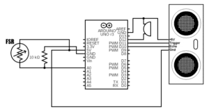
Circuit Diagram (Initial Version)

This is the circuit diagram that we built first. With this circuit, we were able to play notes when we were pressing the force sensitive resistor. 

For code, we first used the code from the site above. Please click here to be directed to my code. Check “Initial_Code.ino”.

This is me testing out our initial version. 

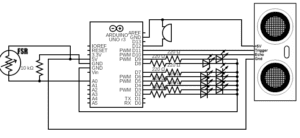
However, we wanted to take a step further, and added an LEDs to the circuit. We made corresponding LED to turn on as we were playing the sound. 

Circuit Diagram (with Modification)

This is the circuit diagram with our modification. For code bit, please click here to be directed to my code. Check “Ultrasonic_withModification.ino”.

For modification, I first, added the pins for the LED, and here, to increase the efficiency of the code, I used for-loop. I also changed the notes, which could be get from the Arduino website. To initialize the mode the pins, I made the Arduino to turned off all the LEDs before turning it on, so that only the corresponding LED gets turned on. 

I think there still is some space for improvement though. As you can see from the second video, two LED sometimes get lighted up. If I have time, I would love to try to fix this. 

Question 1: What did you intend to assemble in the recitation exercise? If your sensor/actuator combination were to be used for pragmatic purposes, who would use it, why would they use it, and how could it be used?

As I described above, we were intending to assemble the instrument although the LED part sometimes is malfunctioning. I think our circuit is only touching the basis of the instrument, so I think we would have to work a lot before being able to use our instrument as a pragmatic purposes. If it were to be used for pragmatic purposes, musicians may use them. However, I think it would be better for children to use it because I think our instrument will be able to trigger curiosity of the children. 

Question 2: Code is often compared to following a recipe or tutorial.  Why do you think that is?

I think I am quite not understanding the question, but if the question is intending to ask why do I think code usually are referred to already made up codes, it is often too cumbersome to code everything. Although we can code everything so that our coding ability increase, I think we do not really have to code everything on our own as long as you know what the borrowed code does. 

Question 3: In Language of New Media, Manovich describes the influence of computers on new media. In what ways do you believe the computer influences our human behaviors?

As I have mentioned in the documentation for recitation 2, our generation probably may be the generation that is first exposed to this large amount of technology. We are currently living amongst the computers because computers are everywhere. Although computer, in general, is influencing human in a good way that we are able to communicate with people who are on the other side of the Earth, easily being able to find information and so forth, I think computer is also influencing human in a bad way. 

Cyber bullying and being anti-social has been a problem for a while. Because people are not seeing each other face to face, people tend to be more rough taking advantage of anonymity. Because people are just looking at their computer all day, people’s social ability tend to be degraded. In addition, people tend to become over dependent on the computers as even I get nervous when my phone or laptop is dying. In conclusion, I think there is two side to the computer being everywhere near us. 

Recitation 2: Arduino Basics by Min Jee (Lisa) Moon

For this recitation, I and my partner Nathalie made 4 circuits in total using a basic Arduino knowledge that we’ve learnt from this week’s classes.

Materials:

From Arduino Kit:

1 * Arduino Uno
1 * USB A to B cable
1 * breadboard
1 * buzzer
2 * LEDs
2 * 220 ohm resistors
2 * 10K ohm resistors
2 * pushbuttons
A handful of jumper cables

From cart:

2 * arcade buttons
1 * Multimeter (optional)

Circuit 1: Fade

For this circuit, I and my partner referred to the circuit drawing below.

Referencing the graph above, this is the circuit diagram that I have drawn using a tool online.

My Version of the Circuit 1 Diagram

Because fading needs an analog value (from 0-255), we connected the lightbulb to one of PWM pins.

Arduino Code for Circuit 1

if we want to change the speed of the fading, we could change the fadeValue (how much it is increased or decreased each time) or change the value inside the delay. 

Circuit 2: toneMelody

For this circuit, I and my partner referred to the circuit drawing below.

Circuit 2

Referencing the graph above, this is the circuit diagram that I have drawn using a tool online.

My Version of the Circuit 2 Diagram
Arduino Code for Circuit 2

There was some notes which was already there for us to use inside the melody[] array, and the duration was set inside the noteDurations[] array to play music. By changing the durations and notes, we could adjust the melody.

Circuit 3: Speed Game

Above is the photo that we referenced for making our circuit. This amazing diagram allowed us to hover over to check which type of resistors we were supposed to use. 

Based off of the diagram above, we tried drawing our own circuit.

My circuit drawing of the above photo

As a result of these work, we managed to build a buzzing game for two players. 

Final Circuit that was built

Code Part

Using the provided code which be found above, we made a working circuit. 

Circuit 4: Four-player Speed Game

Based off of the circuit 3, we combined a breadboard with another team and tried building the 4 player version of the speed game. The circuit diagram looks like below. 

Circuit Diagram for Circuit 4

To make it easier for the viewer to see the diagram, I color coded the diagram.

Player 1: Blue

Player 2: Orange

Player 3: Red

Player 4: Green

Please press here to be directed to the Arduino code.

To switch from two player game to the four player game, we had to make some adjustments in the code such as adding the pins for LED and switches for the player 3 and player 4, (because if one player wins, it means the other players are all losing) adding that other players lost when one reaches 10 press first. 

As a result of these work, we managed to build a buzzing game for four players. 

Question 1: Reflect how you use technology in your daily life and on the circuits you just built. Use the text Physical Computing and your own observations to define interaction.

I remember I as a child that did not know how to use technology at least until I got my very first phone at 3rd grade. Although even then, the technology could barely do the action that we asked the machine to do. As we were growing up, we got more and more used to the life with technology to the point that most people got addicted to technology. Whenever I see a meme that makes fun of how people are so addicted to the technology that they would die when their technological devices shuts off. As mentioned in the Physical Computing, “computers for the rest of you”, as of now, the technology is just everywhere: unlike before, when the computer was just for those experts, technology/computer is spread out everywhere that even the common people can use it. Even when we want to enter our academic building to take this interaction lab lecture, we would have to scan our ID card or use the facial recognition device. 

In the circuits that we have built during the recitation, although it is just touching the basis of interaction since we are just pressing the button expecting our circuits to work or press the reset button on the Arduino expecting the LED to fade in and out, the buzzer to play some music for us, we are constantly interacting: the Arduino is outputting the current after processing our Arduino code (input). 

After reading Physical Computing, the idea of interaction getting more and more clear. Interaction is a constant conversation between two subjects where these two subjects are reacting to each other’s output. Just like one is reacting (commenting) to another as he/she talks, it is interaction because one is processing the words that is said by another (input) and by commenting, it is outputting the reaction. 

Question 2: Why did we use the 10K resistor with the push button?

10K resistor was used with the push button because we are using 5V for all the power supplies, and using 5V may cause too big current for the push button to function. Therefore, it decreases the amount of current to the amount that fits the push button. If we did not use the 10K resistor, the push button may have been damaged. 

Question 3: If you have 100,000 LEDs of any brightness and color at your disposal, what would you make and where would you put it?

If I have 100,000 LEDs, I would love to create an image with LEDs. I still remember the wood mirrors that we saw on the first lecture. If I have that large amount of LEDs, I would love to create a mirror with LED. I would put it in our IMA studio for Professor Godoy to show my project instead of the video to next semester’s interaction lab students.

Recitation 1: Electronics & Soldering by Min Jee (Lisa) Moon

By reading “The Art of Interactive Design”, I started to think carefully about the definition of the term, “interactivity”. So far, I merely thought of the term interactivity as the way an item can meet the user’s need, which I still believe to be similar to the definition that the author has provided, however, found out the difference between my definition with that of the author.

My definition is missing the alternating part. In order for an item or a live being to meet the author’s definition, an item and a live being must alternately show a result that meets each other’s need.

I understand what the author means by that we are losing track of what the interactivity means.

This week, during the recitation session, I and my partner Abby built an electric circuits. We have built three types of circuits.

Materials to build the circuits

Using the above materials, we have built

It made beeping sound whenever me and Abby pressed a switch button
Circuit 1: Door Bell
Circuit 2: Lamp
Circuit 3: Dimmable Lamp

above three circuits. As I and my partner, Abby, pressed on the switch the circuits performed by making a beeping sound or turning on the light bulb, and changed the amount of light of the light bulb by us turning the wheel. These output followed our expectation, which definitely proves these circuits to be an interactive since the circuit processed and outputted the action that meets our expectation after our inputted action of pressing the button or turning the wheel. 

To go further, I know that the circuit we built only has a shallow amount of interaction. For example, the eye tagger that the Zack Lieberman and his fellow team mates built inputs the eye movement of the graffiti artist by using the device (circuit part of the physical computing), processes this inputted eye movement to a form of a graffiti (more towards software part of the computing), and finally outputs this amazing graffiti into the wall outside. However, by interactive design and physical computing meeting together, the paralyzed graffiti artist could interact with the world outside the hospital. 

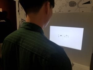
I am very sad that I do not remember the artist’s name, but one day, I and my boyfriend visited a museum and found what I found to be an interactive art.

My boyfriend playing with the letter outputting device

The machine that he is playing with, the user can type in whatever, and the letter changes its form into drawing. The user can also change the font from regular to italic and vice versa. Although some people might not find this art piece interactive, I believe it was also one good example of physical computing and interactive design combined.