Materials
- 1 * Breadboard
- 1 * LM7805 Voltage Regulator
- 1 * Buzzer
- 1 * Push-Button Switch
- 1 * Arcade Button
- 1 * 220-ohm Resistor
- 1 * LED
- 1 * 100 nF (0.1uF) Capacitor
- 1 * 10K ohm Variable Resistor (Potentiometer)
- 1 * 12-volt power supply
- 1 * Barrel Jack
- 1 * Multimeter
- Several Jumper Cables (Hook-up Wires)
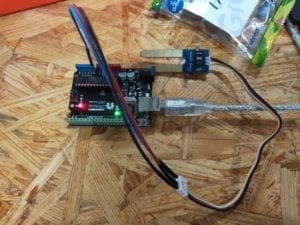
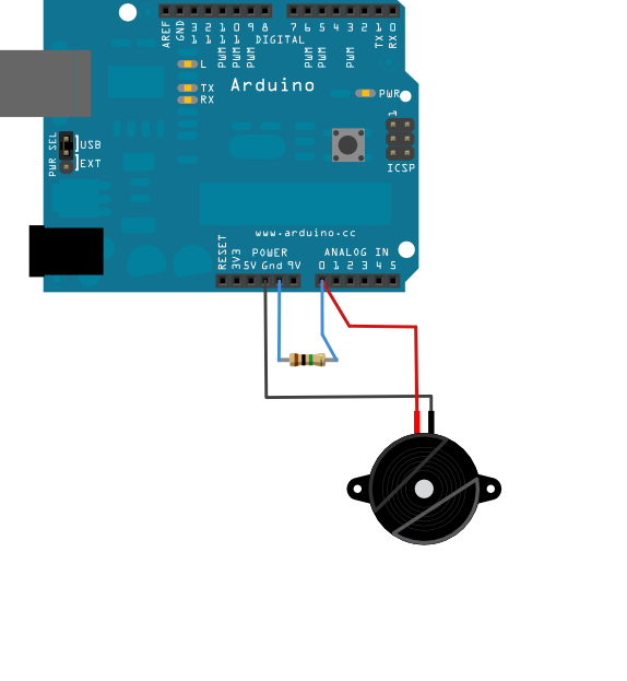
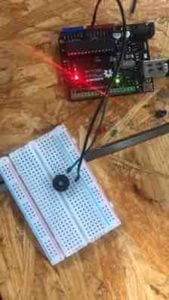
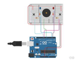
Circuit 1: Door Bell
Here is the circuit diagram:

Image from https://wp.nyu.edu/shanghai-ima-interaction-lab/recitation-1-electronics-soldering/
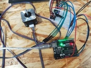
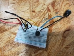
In this circuit, the LM7805 is a voltage regulator integrated circuit which converts the input 12V DC to 5V DC. The 100nF Capacitor connected in parallel with pin1 and pin2 of LM7805 can prevent the regulator from self-exciting. The buzzer we used in class is an active buzzer, which is integrated with an oscillating circuit. So it only needs a stable DC power to drive it. When the button is pressed, the speaker will work.
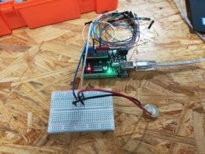
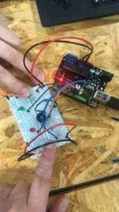
Here is our work:
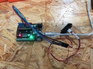
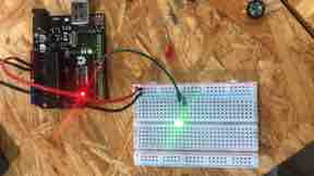
Circuit 2: Lamp
Here is the circuit diagram:

Image from https://wp.nyu.edu/shanghai-ima-interaction-lab/recitation-1-electronics-soldering/
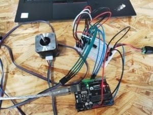
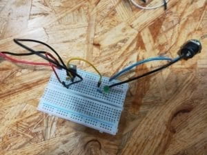
The most part of this circuit is similar to the first one. The only change is that we replaced the buzzer with LED. Moreover, a 220-ohm resistor is connected to LED in series to protect LED by limiting the current.
Here is our work:
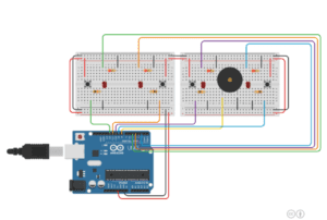
Circuit 3: Dimmable Lamp
Here is the circuit diagram:

Image from https://wp.nyu.edu/shanghai-ima-interaction-lab/recitation-1-electronics-soldering/
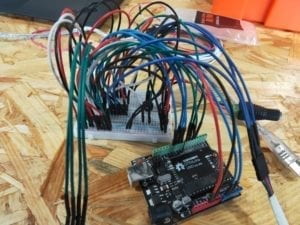
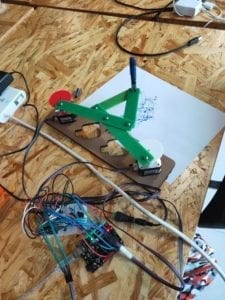
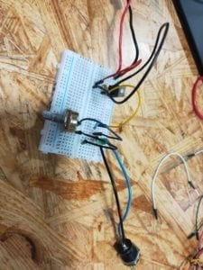
I think this circuit is yet another improved version of the second circuit. By adding a 10K-ohm potentiometer, we can change the resistance of the potentiometer by turning the knob. Correspondingly, the current passes through the LED changes, and the brightness of the LED also changed.
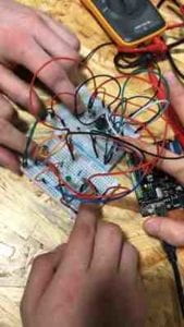
Here is our work:
Thoughts and Knowledge
In the course of the operation, I was fortunate enough not to have any problems. However, I also have some ideas:
Be careful when using the breadboard
The holes on the breadboard are very dense. If you don’t look at it carefully, it is easy to connect jump wires incorrectly, which will cause the circuit to not work properly. So it is important to look at the breadboard from above when connecting the wires.
Measure resistor size by looking at their color rings
The size of a resistor can be measured by the multimeter, which is very helpful. However, the best way to get the accurate resistor size is to look at the color rings. Usually, the last ring indicates precision; each of the other color rings represents a single digit. It can be a bit difficult to find the correct direction, my technique is to observe the distance between rings. The color ring representing precision usually has a larger distance from other color rings. Here is a table for reference:

Image from hahatv5.com
The capacitor is important
Initially, I didn’t know why we need to use a capacitor at the input of the regulator. After checking on the Internet, I know that this capacitor is used to filter the high-frequency signal at the input (capacitor can hinder the high-frequency signal), thus avoiding high-frequency self-excitation of the LM7805. Also, there are cases where another capacitor is used at the output (this time it is stabilizing the output signal).
The buzzer is an active buzzer
Buzzers are usually divided into two types–one is active buzzers, another is passive buzzers. Passive buzzer makes sounds through the vibration of the ceramic piece. To drive a passive buzzer, we need a square wave like this, which periodically drives the ceramic pieces:

Image from phy.ntnu.edu.tw
However, the buzzer we used in class is active buzzers. These buzzers are integrated with oscillating circuit, which generates square wave. So we can directly drive them with DC power.
Questions and Answers
Question 1
After reading The Art of Interactive Design, in what way do you think that the circuits you built today include interactivity? Please explain your answer.
Answer 1
I think the circuits we built include interactivity. Though according to the reading The Art of Interactive Design, interaction should involve listening, thinking and speaking. In the reading, interaction is defined as “a cyclic process in which two actors alternately listen, think, and speak”. Though the logic of the circuits is very simple–just light up the LED when the button is pressed, they still include the key factor of interaction–input, process, and output. Obviously, they cannot speak nor listen, but they can buzz and receive a click. In this sense, we can say that they include interactivity.
Question 2
How can Interaction Design and Physical Computing be used to create Interactive Art? You can reference Zack Lieberman’s video or any other artist that you know.
Answer 2
In the video, interaction design and physical computing are combined to build a helpful system, which helps the artists living in the hospital continue creating. I think interactive art can be achieved only when interaction design and physical computing are combined. Without physical computing, interaction design cannot be turned into reality. In the video, the eye-tracking technology provides the possibility to the whole project. Also, interaction design is necessary. Without the design, physical computing is nothing else but dry technology. In a nutshell, only when interaction design and physical computing are combined, interactive art can be created.