Recitation 8 Documentation

Exercise 1: Make a Processing Etch A Sketch

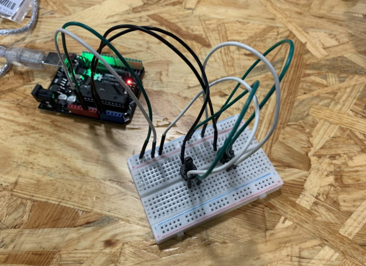
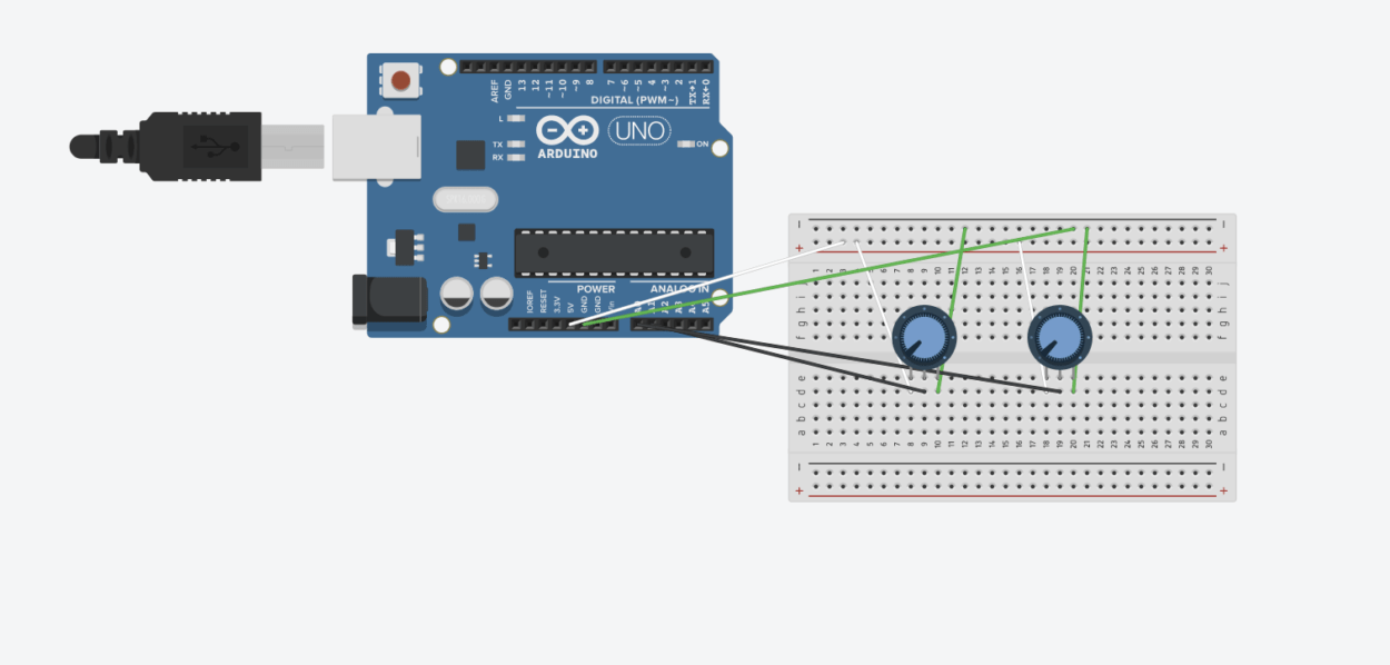
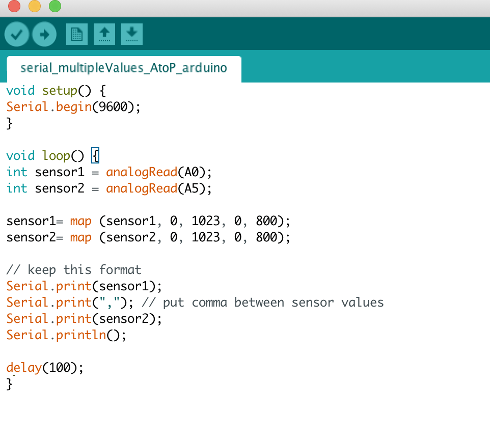
 For exercise 1, we were to use serial communication within Arduino and Processing to send two analog values from Arduino to Processing, first building a circuit with two potentiometers that would read the x and y values of the Etch A Sketch. One of the potentiometers would have to read the “x” values, while the other potentiometer would read the “y” value, in order to create the drawing by turning the potentiometers. Utilizing the serial_multipleValues_AtoP file from class, I modified the code slightly so as to make sure the mapped values would correspond to the correct potentiometers. The circuit was fairly easy to assemble, with the most challenging part being the connection between Arduino and Processing. I had trouble getting the line to be stable, but discovered it was due to loose wiring between the potentiometers on the breadboard.

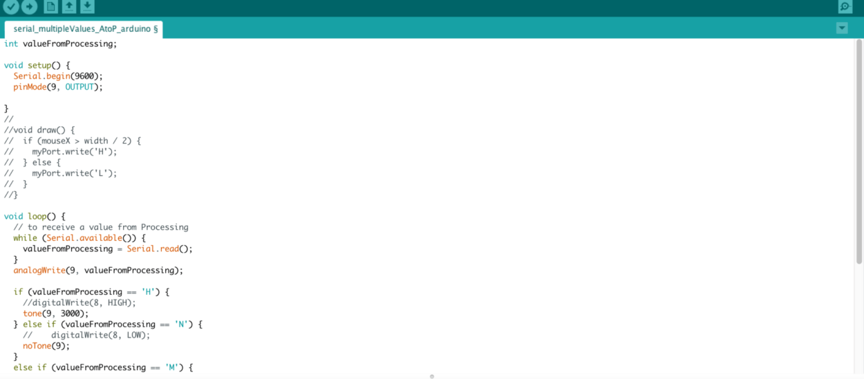
Arduino Code:

Processing Code:

import processing.serial.*;

int NUM_OF_VALUES = 2;
int[] sensorValues;

int prevX;
int prevY;

String myString = null;
Serial myPort;

void setup() {
size(800,800);
background(0);
setupSerial();
}

void draw() {
updateSerial();

printArray(sensorValues);
stroke(250,250,250);
line(prevX, prevY,sensorValues[0],sensorValues[1]);
prevY = sensorValues[1];
prevX = sensorValues[0];
}

void setupSerial() {
printArray(Serial.list());
myPort = new Serial(this, Serial.list()[4], 9600);
// WARNING!
// You will definitely get an error here.
// Change the PORT_INDEX to 0 and try running it again.
// And then, check the list of the ports,
// find the port â€œ/dev/cu.usbmodem—-” or â€œ/dev/tty.usbmodem—-”
// and replace PORT_INDEX above with the index number of the port.

myPort.clear();
// Throw out the first reading,
// in case we started reading in the middle of a string from the sender.
myString = myPort.readStringUntil( 10 ); // 10 = ‘\n’ Linefeed in ASCII
myString = null;

sensorValues = new int[NUM_OF_VALUES];
}

void updateSerial() {
while (myPort.available() > 0) {
myString = myPort.readStringUntil( 10 ); // 10 = ‘\n’ Linefeed in ASCII
if (myString != null) {
String[] serialInArray = split(trim(myString), ",");
if (serialInArray.length == NUM_OF_VALUES) {
for (int i=0; i<serialInArray.length; i++) {
sensorValues[i] = int(serialInArray[i]);
}
}
}
}
}

Exercise 2: Make a musical instrument with Arduino

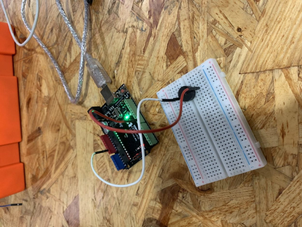
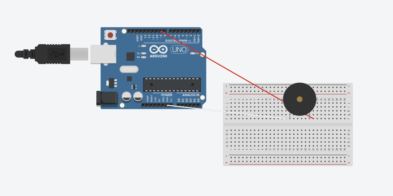
For exercise 2, we were to send values from Processing to Arduino using a buzzer that would play a sound if pressed. We were to map the position of the mouse in respect to the buzzer’s tone. We can use the multiple values from Processing to Arduino for our code, modifying for the duration and frequency of the values. 

import processing.serial.*;

Serial myPort;
int valueFromArduino;

int High;
int Med;
int Low;

void setup() {
  size(500, 500);
  background(0);

  printArray(Serial.list());
  // this prints out the list of all available serial ports on your computer.

  myPort = new Serial(this, Serial.list()[4], 9600);
  // WARNING!
  // You will definitely get an error here.
  // Change the PORT_INDEX to 0 and try running it again.
  // And then, check the list of the ports,
  // find the port "/dev/cu.usbmodem----" or "/dev/tty.usbmodem----" 
  // and replace PORT_INDEX above with the index number of the port.
}


void draw() {
  // to send a value to the Arduino
  High = height;
  Med = 2*height/3;
  Low = height/3;
  if (mousePressed && mouseY > 0 && mouseY < Low) {
    myPort.write('L');
  } else if (mousePressed && mouseY > Low && mouseY < Med) {
    myPort.write('M');
  } else if (mousePressed && mouseY > Med && mouseY < High) {
    myPort.write('H');
  } else {
    myPort.write('N');
  }
  //if (mouseX > width/2) {
  //  myPort.write('H');
  //} else {
  //  myPort.write('L');
  //}
}


Recitation 7 Documentation

Step 1:

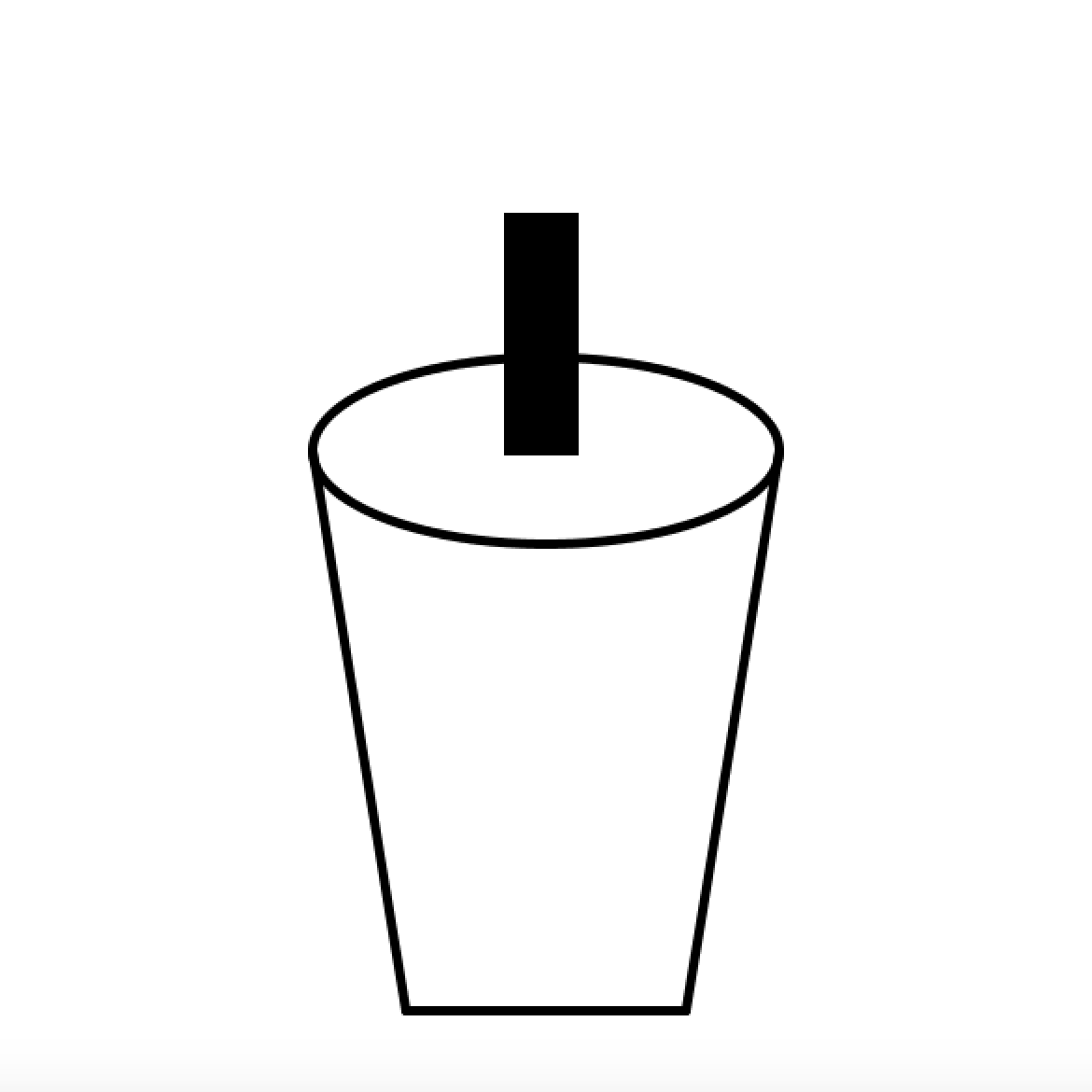
In Step 1, we were required to make a function that would display a graphic that we designed, utilizing the parameters of x position, y position, and color, in addition to using three different shapes. I attempted to create a motif of a cup, with a diagonal pattern on the outside label. I originally wanted to create a motif of bubble tea, but the ellipses that filled the cup were difficult to create into one shape. I used float x and float y for the parameters of the cup, and float a, float b, and float c as the parameters for the color. To create the cup, I used ellipse, line, and quad to form the straw and actual cup. 

Cup
void setup () {
 size (600, 600);
}
  
void draw () {
  background(255);
  cup(300, 250, 255, 255, 255);
}
void cup(float x, float y, float a, float b, float c){
  fill(a, b, c);
  strokeWeight(5);
  ellipse(x, y, 250, 100);
  line(x-125, y, x-75, y+300);
  line(x-75, y+300, x+75, y+300);
  line(x+125, y, x+75, y+300);   
  fill(0);
  quad(x-20, y-125, x+15, y-125, x+15, y, x-20, y);

}

Step 2:

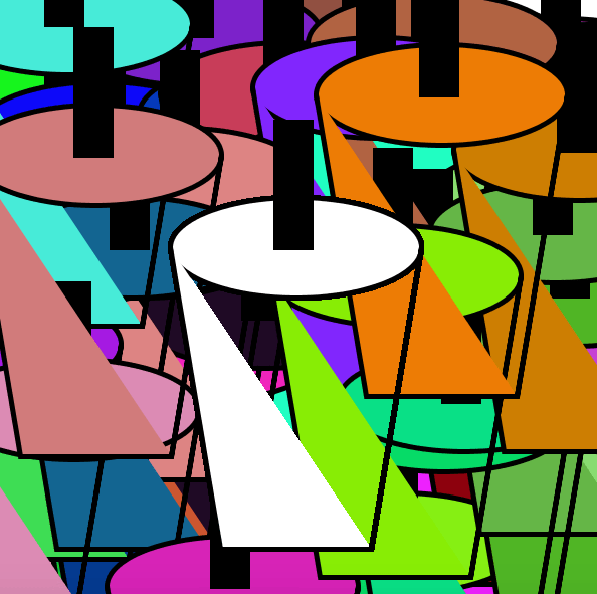
For Step 2, we were to create a for loop in the setup() to display 100 instances of our graphic, in random colors and positions in the rendering. If the for loop is placed in setup(), it produces a static image of the repeated motif in random colors. Since it is in setup(), the code runs once, and does not produce a moving image or a video. The loop function uses random float numbers for both the x and y coordinates, then uses random float numbers for the color. 

Step 2
float x;
float y;
int a;
int b;
int c;
void setup () {
 size (600, 600);
 background(255);
 for(int i=0; i<100; i++){
   x =(random(width));
   y =(random(height));
   a =int(random(255));
   b =int(random(255));
   c =int(random(255));
   cup(x, y, a, b, c);
  }
}
  
void draw () {
cup(300, 250, 255, 255, 255);


}
void cup(float x, float y, int a, int b, int c){
  fill(a, b, c);
  strokeWeight(5);
  ellipse(x, y, 250, 100);
  beginShape();
  vertex(x-125, y);
  vertex(x-75, y+300);
  vertex(x-75, y+300);
  vertex(x+75, y+300);
  vertex(x+125, y);
  vertex(x+75, y+300); 
  endShape();
  fill(0);
  quad(x-20, y-125, x+15, y-125, x+15, y, x-20, y);
  
 
}


When the for loop is under draw(), the function runs continuously from top to bottom until the program is stopped, resulting in a moving image and a video. In contrast to the static picture of the for loop under setup(), the end result is a video that runs 100 times of the original graphic.

float x;
float y;
int a;
int b;
int c;
void setup () {
 size (600, 600);
 background(255);
 
}
  
void draw () {
for(int i=0; i<100; i++){
   x =(random(width));
   y =(random(height));
   a =int(random(255));
   b =int(random(255));
   c =int(random(255));
   cup(x, y, a, b, c);
  }
}
void cup(float x, float y, int a, int b, int c){
  fill(a, b, c);
  strokeWeight(5);
  ellipse(x, y, 250, 100);
  beginShape();
  vertex(x-125, y);
  vertex(x-75, y+300);
  vertex(x-75, y+300);
  vertex(x+75, y+300);
  vertex(x+125, y);
  vertex(x+75, y+300); 
  endShape();
  fill(0);
  quad(x-20, y-125, x+15, y-125, x+15, y, x-20, y);
   
}

Step 3:

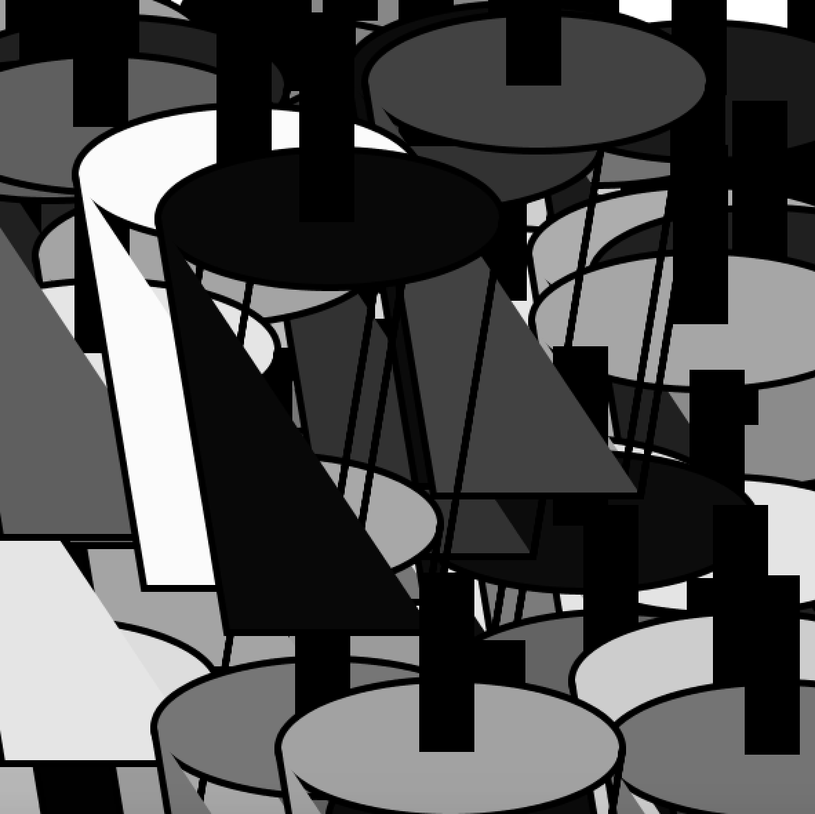
For Step 3, we were instructed to create 3 arrays to store the x, y, and color data. By setting float [] to different values, we were able to state these specific values. The array stores values under a set of data elements, capable of holding any type of data for it to be individually assigned and read. 

float [] x = new float[100];
float [] y = new float[100];
float [] z = new float[100];
void setup () {
 size (600, 600);
for(int i=0; i<x.length; i++){
   x[i] =random(width);
   y[i] =random(height);
   z[i] =random(255);
  }
 printArray(x);
 printArray(y);
 printArray(z); 
}
  
void draw () {
  background(255);
 for(int i=0; i<x.length; i++){
 cup(x[i],y[i],z[i]);
  }
}
void cup(float x, float y, float z){
  fill(z);
  strokeWeight(5);
  ellipse(x, y, 250, 100);
  beginShape();
  vertex(x-125, y);
  vertex(x-75, y+300);
  vertex(x-75, y+300);
  vertex(x+75, y+300);
  vertex(x+125, y);
  vertex(x+75, y+300); 
  endShape();
  fill(0);
  quad(x-20, y-125, x+15, y-125, x+15, y, x-20, y);
   
}

Step 4:

For Step 4, we were required to add individual movements to each instance, through modifying the content of the x and y arrays. The x and y arrays were assigned to move through the line of code “x[i] += random(-30, 30);
y[i] += random(-30, 30);”, and the speed at which the movements ran would increase as these respective numbers increased. 

float [] x = new float[100];
float [] y = new float[100];
float [] z = new float[100];
void setup () {
 size (600, 600);
for(int i=0; i<x.length; i++){
   x[i] =random(width);
   y[i] =random(height);
   z[i] =random(255);
  }
 printArray(x);
 printArray(y);
 printArray(z); 
}
  
void draw () {
  background(255);
 for(int i=0; i<x.length; i++){
 cup(x[i],y[i],z[i]);
 x[i] += random(-30, 30);
 y[i] += random(-30, 30);
  }
}
void cup(float x, float y, float z){
  fill(z);
  strokeWeight(5);
  ellipse(x, y, 250, 100);
  beginShape();
  vertex(x-125, y);
  vertex(x-75, y+300);
  vertex(x-75, y+300);
  vertex(x+75, y+300);
  vertex(x+125, y);
  vertex(x+75, y+300); 
  endShape();
  fill(0);
  quad(x-20, y-125, x+15, y-125, x+15, y, x-20, y);
   
}

Question 1:

In your own words, please explain the difference between having your for loop from Step 2 in setup() as opposed to in draw().

The difference between having the for loop in setup() as opposed to in draw() is that in setup(), the code runs only once and generates a still image, as it is not being constantly repeated for it to be an active image. If the for loop is placed under draw(), however, the for loop is being continuously executed until the program is stopped or noLoop() is called. Under draw(), the function can create animations as it is constantly being repeated. 

Question 2:

What is the benefit of using arrays?  How might you use arrays in a potential project?

The benefit of using arrays is that you are able to hold any type of data, ranging from numbers, characters, sentences, or boolean values. These types of data are individually assigned and read within each array, making it simpler for the code to be designed. Arrays allow us to store many variables that would normally take much time to set up each individual value, but arrays are instead able to assign values to these data. I might use arrays in a potential project if there are multiple values that would need to be stored, or a multitude of shapes and designs within the function.

Final Project Proposal

  1. Chance

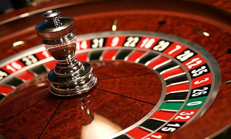
The original game Russian Roulette is a game of chance, highly dependent on the user’s time and reaction speed to game itself. However, on lighter terms, this game would become an interactive game between the user, using LEDs to pinpoint which LED the user should stop on. From our previous project, we realized the game should be as straightforward for the player to understand, in order to not disrupt the game by distracting them with other instructions or LEDs. The project would be intended for people seeking to improve their reaction time to visual cues, or anyone looking to play a fun game based on chance. I researched the actual Russian Roulette game, which instead involves the player and a revolver, which proves much more lethal when viewed in a context of a game. But the ideology and instructions behind the game can be further narrowed down to a simple game using LEDs and buzzers as a penalty. The challenge I would seek to address is its constraints of being too simple at times, and searching for a way to make the game more complex, yet not too complex so as to confuse the player. 

Russian Roulette

2. Labyrinth Maze

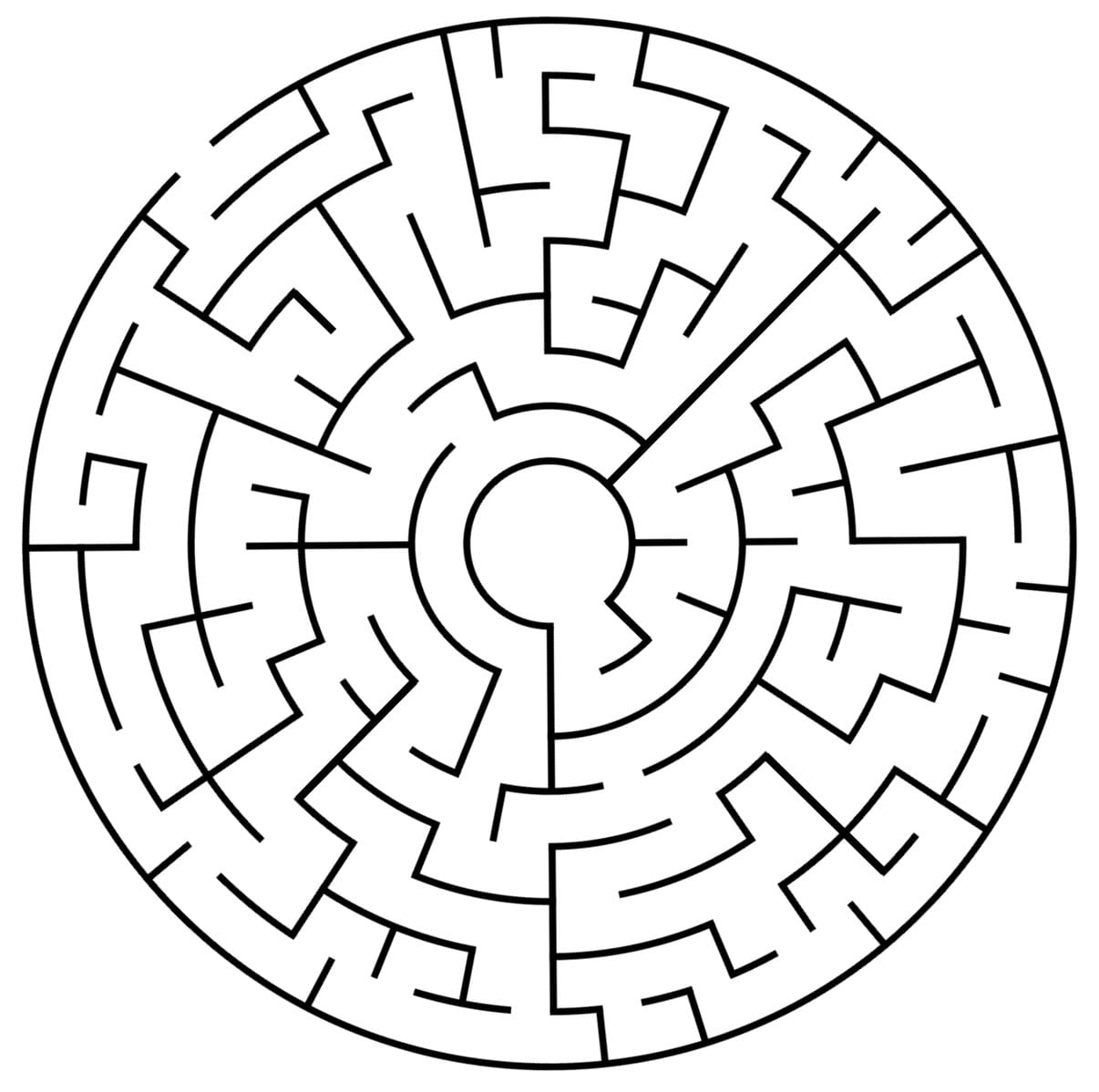
Inspired by mazes and labyrinth mazes, these complex puzzles require the player to choose different paths and directions, with each choice ultimately influencing the end result of the game. These mazes may have several entrances and exits, as well as dead ends to confuse the player. In a labyrinth maze, however, there is only one universal exit and entry, though the path from entrance and exit is still highly complex. This game would be controlled through a joystick, similar to those found in arcade games, to direct the movement of the marble that would be utilized in the game. The marble would act as the physical “player” in the game, starting from the point of entry to the point of exit. The player would use the joystick that would tilt the box in various directions, allowing for the marble to follow the path it takes. The challenge I would seek to address is a way for the game to stabilize itself on an angle, allowing for the game to physically tilt from side to side, without it being too unstable for the player to control. It would additionally have to have enough control for the marble to go in different directions, with the walls having to have a specific width for the marble to glide smoothly through. My intended audience would be anyone looking to challenge their brain through different forms of strategizing, helping them in navigating through a challenging maze.  

Maze

3. Fill the Line

Inspired by the popular game Tetris, a tile-matching puzzle video game popularized throughout history, this project would aim to create a video game similar to those found on arcade games, video game consoles, or digital apps on mobile phones. Tetris is played through the use of game pieces in the form of geometrical shapes, also known as tetrominoes, that are typically composed of four blocks. These pieces randomly fall down onto the playing field of the game, while the player can rotate and manipulate the pieces as desired to fit at the bottom of the game. They should aim to fill a solid horizontal line without leaving any gaps, so it can disappear and clear more room for the tetrominoes. When all the lines are filled and no more pieces can fit at the top, the game is over. Many renditions of the game Tetris can go on for an extremely long period of time, as the time for the blocks falling down decreases, the difficulty level additionally increases. The original game influenced my intended design of the project, as it is continuously allowing for interaction between the user and the project, with the user navigating each piece of the puzzle for it to fit at the bottom. The challenge I would seek to address is how to incorporate the function of displaying the game itself, and allow the user to navigate and manipulate the functions of controlling the pieces itself. The intended audience would be anyone seeking to increase brain efficiency, as this project involves hand-eye coordination and problem-solving ability. 

Final Project: Preparatory Research and Analysis

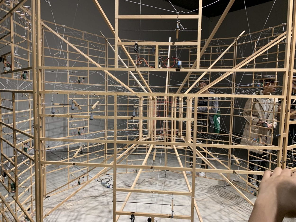
The Chronus exhibition, Just What Is It That Makes Today’s Computers So Intriguing, So Nonsensical, proved incredibly inspiring, as its physical conception was compelling in both its final rendering and the process behind creating its design. Each of the installations was captivating in its own way, presenting something similar to that of a performance with its kinetic movements. The sculpture I found most enthralling at the exhibition was Rechnender Raum, by Ralf Baecker, which is described as doing “the immaculate deed of measuring and adapting space with a neural network built of beechwood sticks, rubber bands, fiber strings and servo motors, turning the logic of a consumer computer inside out” (Chronus Art Center). Its use of servo motors in the final installation as part of its physical rendition proved very intriguing, as we would typically hide the physical motors and wires in our own projects. Instead, Baecker decided to include the servo motors as part of the physical art sculpture, which overall added to its unique final presentation.

Rechnender Raum,by Ralf Baecker

Compared to other exhibitions of non-technology based art work, this exhibition was much more engaging with the visitors in terms of creating a unique experience between the artwork and the viewer. Typically, the viewer examines a flat, usually 2D painting or drawing, not actively engaging with the viewer in the sense of using different moving parts as part of its installation. The Chronus exhibition provided a way for every visitor to perceive the sculptures as something entirely different, as each moving part results in a different perception of what the sculpture is and what it represents. By seeing each component of an installation move and interact with the other elements of the installation, it provided for a more immersive experience with the installation itself, instead of just simply viewing the artwork as a whole.

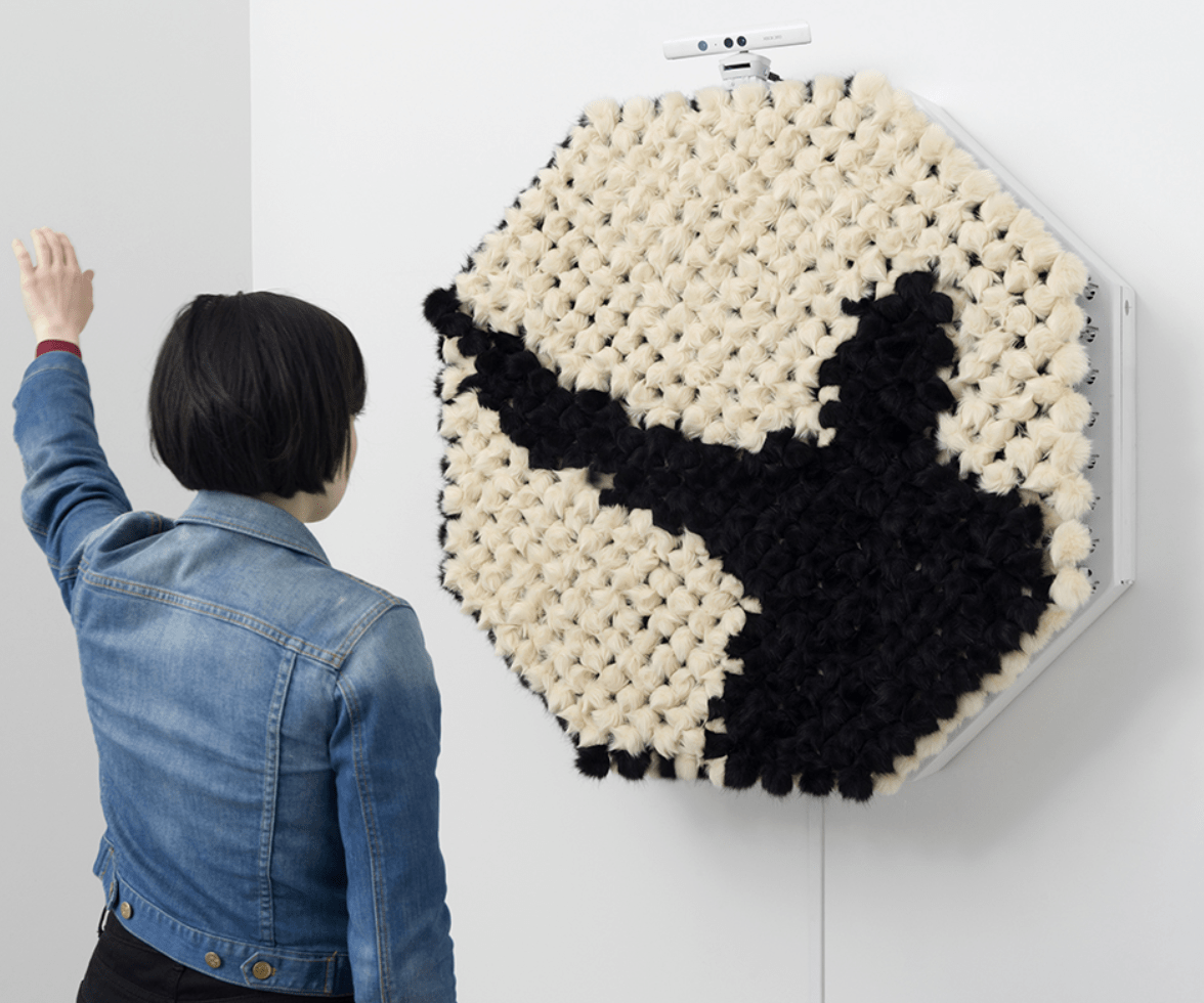
Rozin’s PomPom mirror

When researching two other interactive projects, I first looked into NYU Professor Daniel Rozin’s interactive art. I stumbled onto his work through a small feature documentary created by WIRED magazine. Rozin’s work mainly involves the use of motors, sensors and different materials, all acting as different types of mirrors. Specifically, I chose the PomPom Mirror, which makes use of 464 small motors, an Xbox Kinect sensor, and 928 faux fur pom poms. The piece itself detects movement from the user, which translates to a mirror image projected onto the pom pom material. The piece itself is deceivingly complex, requiring Rozin to create his own software for the piece, and individually programming each of the motors to move in a unified manner. I believe that Rozin’s art proves itself to be a successful example of an interactive experience as it has no learning curve. I believe that Rozin’s PomPom mirror displays interactivity through its cyclical process with corresponding to the user’s input. When the user moves, the piece responds to their input, thereby changing the overall piece as a result of the user’s interaction. The piece itself poses no type of difficulty, the design is intuitive and easily accessible; the only interaction necessary for the viewer is their own movement. 

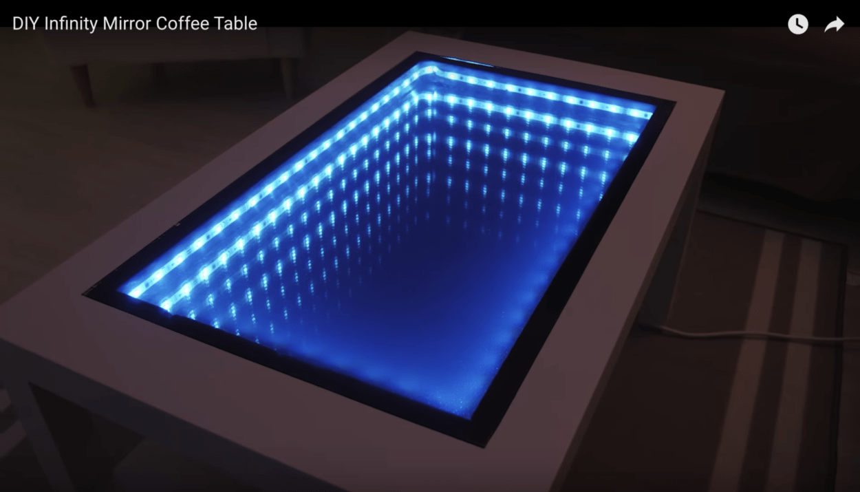
 DIY Infinity Mirror Table

Additionally, when researching for more interactive projects, I found a walkthrough for a D.I.Y Interactive Infinity mirror table. The table itself made use of mirrors and lights, creating an illusion of a table with an empty center. The illusion itself proves to be an interesting piece; however, when compared to Rozin’s work and other interactive projects, the table fails to be as successful. Although the table is visually striking, the interactivity of the table falls short. Aside from the ability to change color, the table does not pose any form of interactivity. Unlike Rozin’s PomPom mirror, the table itself does not react to any real time input from the user, only changing when a button is pressed. Although interactive in certain aspects, the infinity mirror table proves to be a less successful example of interactivity within a project. 

During the group project, I defined “interaction” as two participants working and influencing each other, or how one participant responds to another participant’s input. Based on the initial definition and my experience developing and executing my midterm project, I redefined my interpretation of interaction to reimagine it as a cyclical process. When conceptualizing what the midterm project could be, many of our original renderings proved very isolated in its process, with the user interacting with the device, then the device reacts to the user, then ending the overall interactive cycle. When creating our project, we wanted to produce something closer to a process between the two participants, an ongoing process of interaction, with constant input and output from both users. For an interactive experience to be successful, it has to be — quite obviously — an experience, in which the “experience” does not end after one user interacts and the device interacts. Instead, the two have to be constantly in action, interacting with each other to create a more immersive experience. This is most similar to The Art of Interactive Design, which most clearly defines interaction as “a cyclic process in which two actors alternately listen, think, and speak,” through comparing the act of interaction similar to a conversation (5). I think that more precisely, however, interaction is typically composed of three steps: input, output, and processing, as outlined in Introduction to Physical Computing (Igoe & O’Sullivan, 20). Interactivity is defined upon the notion of the physical experience between involving two people involved, who collectively react with each other. 

Works Cited:

http://www.smoothware.com/danny/contact.html

https:// www.youtube.com/watch?v=OasbgnLOuPI

Recitation 6 Documentation

Recitation Exercise:

For this week’s recitation, we were to individually create a project that involved some level of interaction with either the keyboard or mouse. I chose to animate my creation from Recitation 5 using interaction involving the press of a mouse. I imagined the painting from last week in terms of its actual installment, in which the artist painted the illustration on a large section of a wall, and could then repaint the background in different colors to create a new, contrasting painting every time. 

I wanted to add the mousePressed() function into the code to call the code once every time a mouse button is pressed. My idea was that the user could create a different rendering of the painting each time, by making the background a random fill color each time.

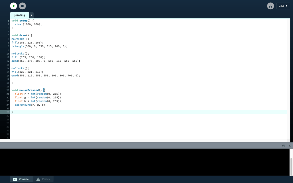
Under void mousePressed(), I assigned each value for a color to float r, float g, float b, in order to randomize the colors within each primary color. This integer would be within 0 to 255 for red, green, and blue. Then, combining this randomization, I deleted the background from the original code and put in background(r, g, b) to change the background each time. 

I originally had problems getting the background to change at all, then realized I had to remove the line of background code from the original setup. When I removed it, the code started working. I also had to implement void setup and void draw, changing it from static mode to active mode. 

Code of the interactive project

Additional Recitation Homework:

Step 1:

Create a Processing sketch with a circle or square at the center of the screen. Your canvas size should be 600 x 600.

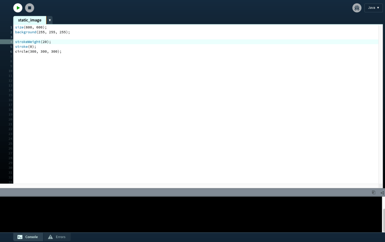
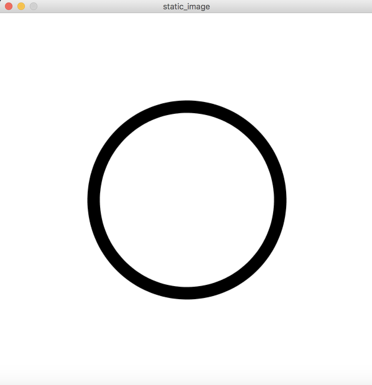
This was fairly simple to code, as it was merely a static image of a circle. 

Step 2:

Next, modify that Processing sketch so that the circle or square periodically expands and contracts, like the circle in this gif.

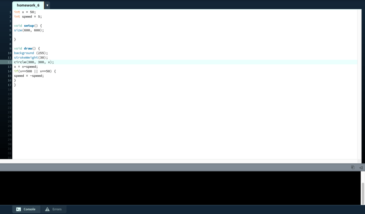
The second part gave me more trouble, as I had many difficulties making the circle stop expanding, and instead start contracting as it became bigger. I changed the code from static to active mode, as the final product would be moving, and therefore be active. I started off with setting the integer “x” to 50 to represent the diameter of the circle, in order to control how the circle expanded and contracted like in the example. I then set the integer for speed to 5, to ensure that it would expand and contract at a constant speed. I moved the line of background code under void draw(), to continuously execute that line of code contained inside its block. I originally had the background(255) under void setup(), which stopped the circle from contracting once it hit a certain point. When I moved it under void draw(), it then worked correctly. I then used the if statement that we learned in class to create 2 statements that would allow the circle to expand and contract. One would be for when the diameter hit 50, and one would be for when the diameter hit 500. I combined these 2 statements using || (logical OR) function, which compares 2 expressions and returns true if one or both evaluate to true. Both of the statements under if (x==500 || x==50) evaluate to true, so I decided to use this function. These would then correspond to either a positive speed of 5, or a negative speed of 5, in order for the circle to expand and contract. 

Step 3:

Then, modify the Processing sketch so that the the the outline changes color smoothly, as seen in the gif below. HINT: set the colorMode() to HSB.

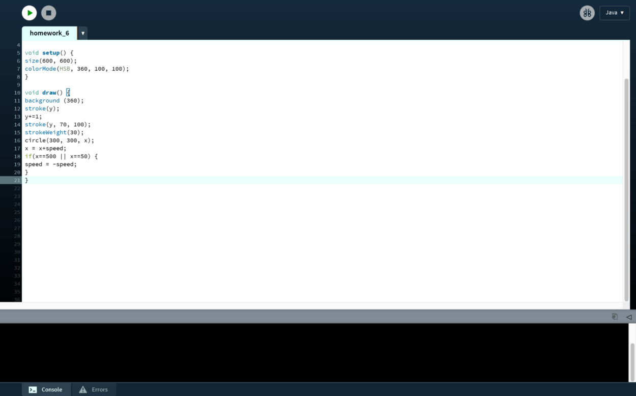
Using the hint of setting the colorMode() to HSB, I changed the range of values for colors using the code colorMode(HSB, 360, 100, 100). I set the integer y to stand for the colors within HSB, using stroke to set the color for drawing the line/border around the circle. 

Step 4:

Finally, modify that Processing sketch so that the circle or square moves around the canvas based on your keyboard’s arrow key input. As an added bonus, you may make your canvas’ edges a border that the circle or square cannot pass.

In order to make the circle move based on my keyboard’s arrow key input, I had to use void keyPressed() in order to detect special keys, such as UP, DOWN, LEFT, and RIGHT. This only works when using the conditional if (key==CODED), to ensure the keys are coded. 

Here is the list of the most interesting functions I used while creating an interactive animation:

  • colorMode()
  • keyPressed()
  • keyCode ==