“Story of Your Life” Reading

  1. How do aliens in the story using language and communication style different from the human language (oral, pictographic, phonetic, etc.)?

Aliens in this story use “logographic” script, which is phonetically written, and used in Chinese characters as opposed to English and other standard alphabetic script. Dr. Banks realizes that the heptapods’ written and spoken languages are unrelated to each other, different from the human language which are usually intertwined with each other in order to serve as a means of communication from a vocal and hearing standpoint. However, in contrast to logographic languages, the aliens’ script is composed of intricate graphic designs, yet not in any sort of linear fashion, which would make it hard to widely replicate and understand in the human language. The aliens’ “seismographic” language conveys meaning without reference to speech, meaning their visual syntax is unrelated to the syntax for their spoken language, rendering it much different to the human language as the two are connected.

2. How does the physical structure of our body inform the way we communicate? How about the aliens?

The physical structure of our body informs the way we communicate since our anatomy, specifically the larynx, is able to physically create the sounds that we dictate as our speech. Establishing vocal communications is only possible through reproducing sounds that our human vocal tract and hearing the sounds back through our ears. This difference in anatomy makes it interesting to point out that since the heptapods’ bodies have no distinct direction, their script can also be written and interpreted in any direction with ease. If this were translated into human language, all scripts would lose sense of meaning as there are logical directions behind each stroke and position of a word in a sentence.

Digital Maze – Lydia Zhao – Eric

CONCEPTION AND DESIGN:

In understanding how users were to interact with my project, I wanted the physical layout of my maze to be as clear as possible to the user without a detailed explanation or a given set of instructions. The user should be able to decipher how to play the game without any prior knowledge just by observing the physical components of the project. Accounting for such decisions, I decided to place a joystick at the very front of the project, implicitly communicating to the user of the most direct action to control the maze. Behind the joystick is the maze itself, notifying the user that the joystick should be able to control the physical component of the maze. I additionally contemplated using 2 joysticks instead of 1, in order for them to control a separate axis and servo motor, but decided this could possibly confuse the user into which joystick were to control which motor and axis, forcing them to remember which axes to control. In addition, I wanted the user to realize the objective of the game, that they had to complete the maze from start to finish. I added a ‘start’ and ‘finish’ label to both openings of the maze, in order to be more easily recognized by the user to which opening was the start and finish. I used cardboard to ‘prototype’ my project, as it gave me the most direct control over the sizes and design of the physical layout, especially in the maze. I could alter the difficulty of the physical maze and its walls, by cutting the cardboard to be shorter or longer, or hot gluing a dead end together to increase the difficulty of a certain path. These dead ends or different pathways allows the user to challenge the user to find the means of escaping the ‘obstacles’ and finishing the maze. I hoped that the maze could boost problem solving skills, and increase the user’s patience and persistence levels. If they fell into a dead end, they would have to restart the path and find another path in order to complete their goal of escaping the maze. The physical 3-dimensional aspect of the maze, in comparison to the typical 2-dimensional maze, allows for increased hand-eye coordination of both using the joystick and looking at the maze and the different way it tilts. 
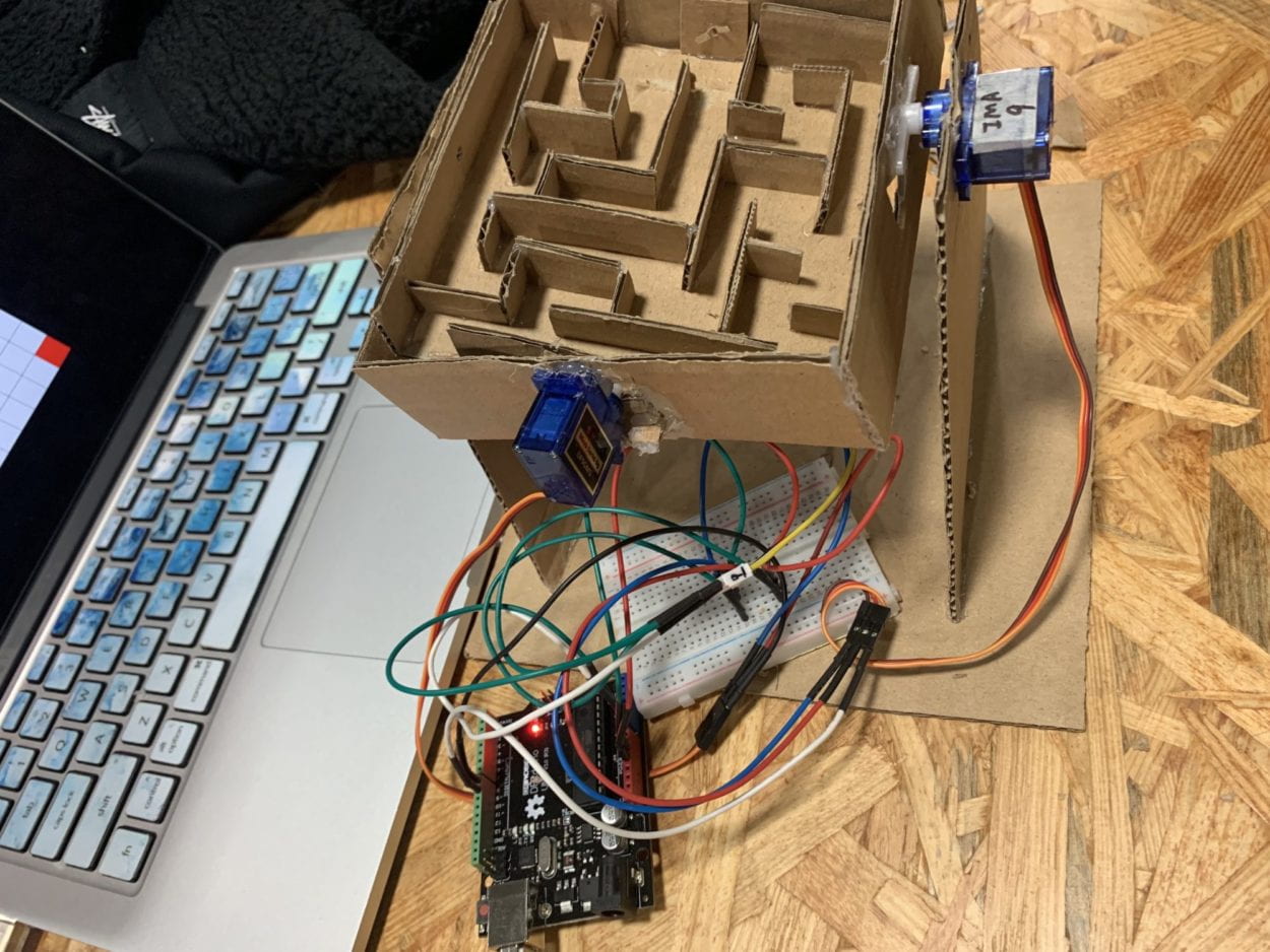
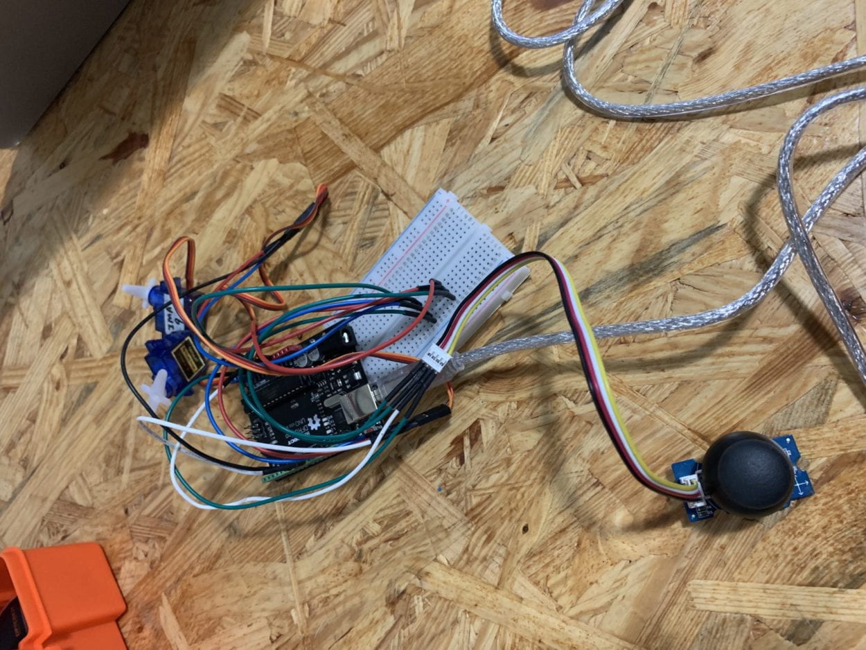
Regarding the physical elements of the maze, I used both a joystick and 2 servo motors. I used the joystick to better control the 4 directions that the maze could tilt in, allowing for the most accessible way of controlling the maze. The joystick is capable of communicating 2D motion (2-axis) to Arduino, meaning that by using 2 servo motors, I could make the overall project in 3D instead of just incorporating 2-dimensional motion. The joystick uses 2 independent 10K potentiometers (one for each axis), providing analog input in the form of an effortless control stick form. I used the two servo motors to control the x-axis and y-axis of the maze, allowing it to tilt both up & down and left & right. The servo motors can precisely control the position of their shaft, so they were the perfect choice to control the axes of the maze. In order to simultaneously control the x-axis and y-axis of the maze, there needed to be a servo motor attached to two different walls within the maze, one attached to a larger square surrounding the maze, and one attached to the physical maze itself. This way, the servo motors could individually control each axis without interference of the other axis, or without limiting the motions of one motor. 
Another option I experimented with was the digital tilt sensor, a sensor capable of detecting the orientation of an object, and giving an output of either High or Low. I rejected this component because the digital tilt sensor typically is used alongside an LED or buzzer, or another component that reacts to the two outputs given by the sensor. Instead, I wanted the user to be able to have more control over how much they were allowed to tilt the maze, instead of being restricted to being high or low. Additionally, I was not recording the input of the orientation of the maze, and therefore did not need the degree of how much the sensor was being tilted. Thus, I decided to use the servo motors with the joystick, to give the user as much control as possible to however much they wanted to tilt the maze. These components were best suited for my product purpose, as it allowed for total rotation of every direction of the maze, and the servo motors reacted quite smoothly given the input from the joystick. The speed at which the servo motors went could additionally be controlled through Arduino, giving me more command over how fast the maze could tilt, which would be less possible if I were to have used a sensor instead. 
FABRICATION AND PRODUCTION:

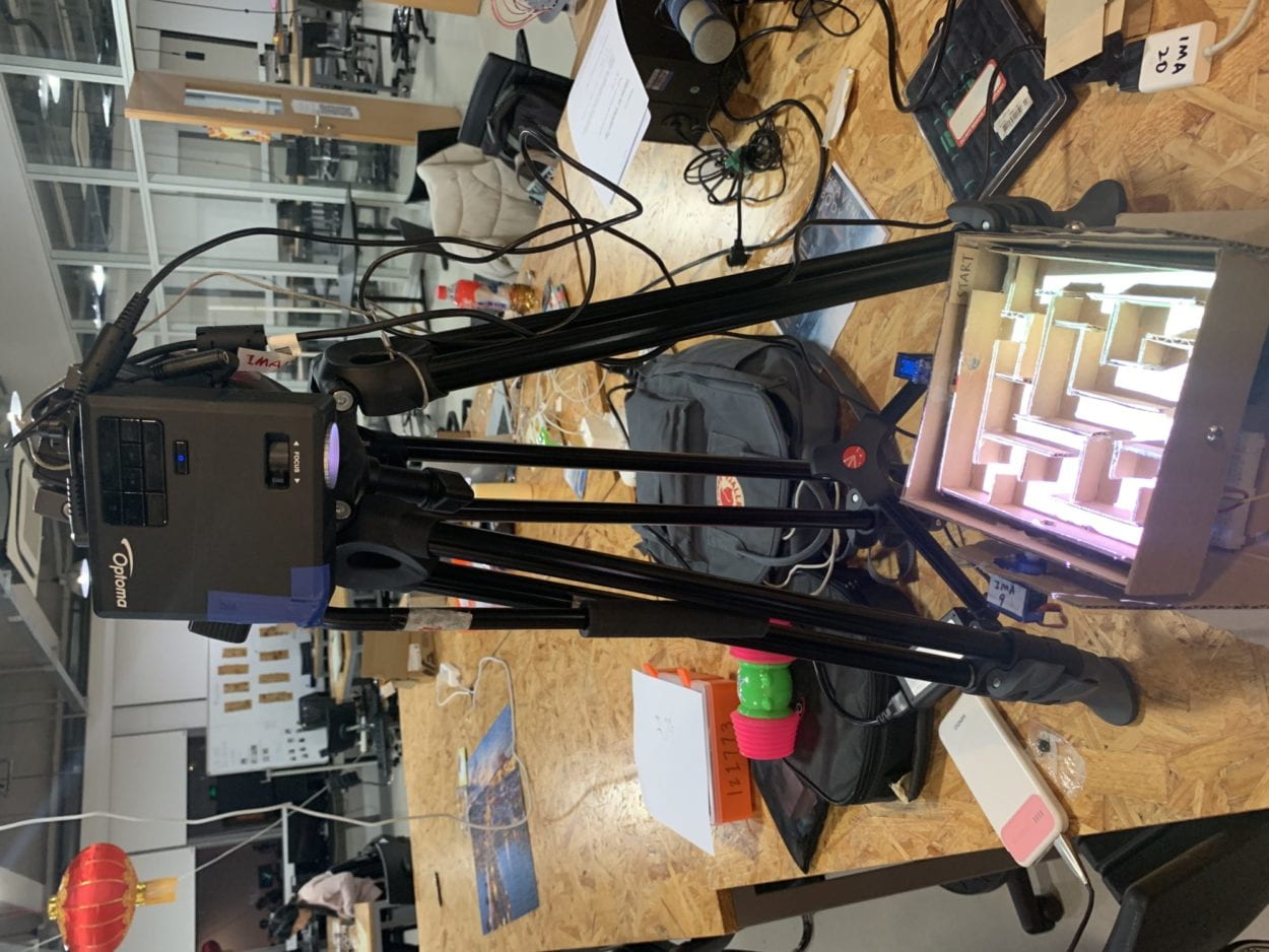
During the User Testing Session, one of my servo motors failed to work, meaning only the y-axis of my maze was able to tilt. At this time, I did not glue down the servo horn to the maze, and did not screw in the horn into the motor, meaning the horn would constantly pop out if it tilted too much. Therefore, I had to ensure each wall was corresponding to a different motor, so that the maze could rotate in each direction. I additionally created a box for the physical maze to sit on, so it would be the perfect height under the projector. I originally had the projector on the floor with its legs almost completely extended, but in order for the user to better access the maze, I then moved it onto the table directly perpendicular to the maze. This way, the user’s view was not obstructed by the projector in front of the maze. The various production choices I made were to better allow for the movement of the two separate axes, and to make the design more clear to the user.
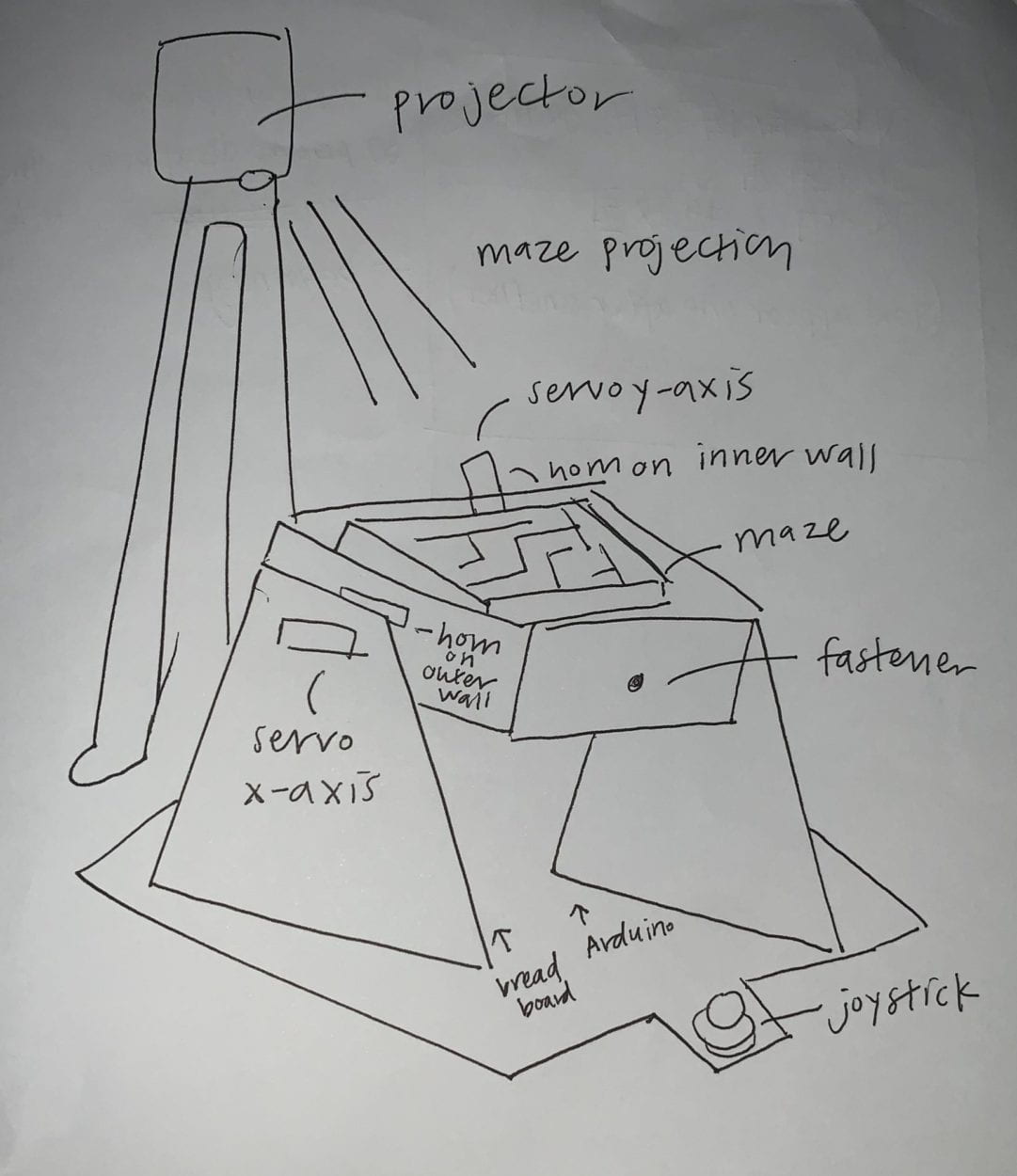
CONCLUSIONS:

The goal of my project was to create a fun, interactive game that would allow the user to improve their problem solving skills, cognitive thought processes, while increasing their patience and persistence levels through solving a maze. My project aligns with the definition of interaction that includes three steps:  input, output, and processing, as outlined in Introduction to Physical Computing (Igoe & O’Sullivan, 20). This maze closely aligns with how I define interactivity, as the user is constantly giving input through moving the joystick in different directions in order to tilt the maze, while the maze is moving the ball throughout its different pathways. Interaction can additionally be described as “a cyclic process in which two actors alternately listen, think, and speak,” as outlined in The Art of Interactive Design (5). There must be a continuous loop of the user and the device interacting with one another, seen in the device tilting and the ball rolling in response to how the user decides to interact and move the joystick. Based on my definition of interaction and my expectation of the audience’s response, the audience closely interacted with my object through first controlling the joystick, which would tilt the maze in a specific direction. In response to this, the ball moves and navigates the maze, then the user must strategically maneuver the joystick in order to avoid the red squares, or the obstacle. In this way, the user is closely interacting with the project at all times, as they have certain obstacles to avoid in order to complete the maze successfully. If I had more time, I would attempt to projection mapping, in order to have the projection accurately map the coordinates of the maze. This way, it would not distort the projection whenever the user would tilt the maze. I already attempted to use color tracking in order to track the position of the ball, hoping to map if and when the ball would touch the red obstacles, thereby allowing the user to know when they have hit an obstacle. In addition, if I could somehow successfully track all these components, I could give a score or time upon successful completion of the game, and create a scoreboard of the fastest times completed. I learned from my setbacks that they are utterly necessary in order to improve any iteration of a project or design, as only through setbacks can you determine what is necessary to enhance any elements of the project. I took away from my accomplishments that people enjoyed playing the game, especially in its physical aspect of tilting the maze and following the ball from start to finish. The significance of this game allows us to realize that even in our daily fast-paced, busy lives, we must take a second to exercise our cognitive capabilities and improve our patience levels and reactions to daily triggers. By incorporating these mentally challenging skills in this game, we can simultaneously enjoy a fun, interactive device while promoting better mental capabilities.

Code for Processing:

boolean[][] grid = new boolean[12][12];

void setup () {
  background(0);
  fullScreen();

  for (int x = 0; x<12; x++) {
    for (int y = 0; y<12; y++) { 

      float r = random(100);
      if (r < 2) { // chance of a square being red
        grid[x][y] = true;
      } else {
        grid[x][y] = false;
      }
      
    }
  }
}

void draw() {
  fill(255);
  translate(width/2-300, height/2-300);
  rect(0, 0, 600, 600);

  rect(0, 0, 100, 100);
  rect(100, 0, 100, 100);
  rect(200, 0, 100, 100);
  
  for (int x = 0; x<12; x++) {
    for (int y = 0; y<12; y++) { 
      
      if(grid[x][y] == true) {
        if(millis() % 3500 < 1000) {
          fill(255, 0, 0);
        } else {
          fill(255);  
        }
      } else {
        fill(255);  
      }
      rect(x*50, y*50, 50, 50);
    }
  }
}

Code for Arduino: 

#include <Servo.h>
Servo servo1;
Servo servo2;
int x_key = A1;
int y_key = A0;
int x_pos;
int y_pos;
int servo1_pin = 8;
int servo2_pin = 9;
int initial_position = 90; // horizontal servo
int initial_position1 = 90;

void setup ( ) {
Serial.begin(9600) ;
servo1.attach (servo1_pin) ;
servo2.attach (servo2_pin) ;
servo1.write(initial_position);
servo2.write(initial_position1);
pinMode (x_key, INPUT) ;
pinMode (y_key, INPUT) ;
}

void loop ( ) {
x_pos = analogRead(x_key) ;
y_pos = analogRead(y_key) ;

// servo at pin 8
if (x_pos < 300) {
if (initial_position < 10) {
}
else {
initial_position = initial_position – 4;
servo2.write (initial_position);
delay (100);
}
}

if (x_pos > 700) {
if (initial_position > 180) {
}
else {
initial_position = initial_position + 4;
servo2.write ( initial_position );
delay (100);
}
}

if (y_pos < 300) {
if (initial_position1 > 180) {
}
else {
initial_position1 = initial_position1 + 4;
servo1.write ( initial_position1 ) ;
delay (100);
}
}
if (y_pos > 700) {
if (initial_position1 < 10) {
}
else {
initial_position1 = initial_position1 – 4;
servo1.write ( initial_position1 ) ;
delay (100);
}
}
}

Recitation 10 Documentation

For this recitation, we first explored the map() function, which changes a range of values into another a range of values. We were to use the map() function within the serial communication workshop. In Arduino, we could use map() for the potentiometers, while in Processing, we could use map() for the horizontal and vertical coordinates of mouseX and mouseY. 

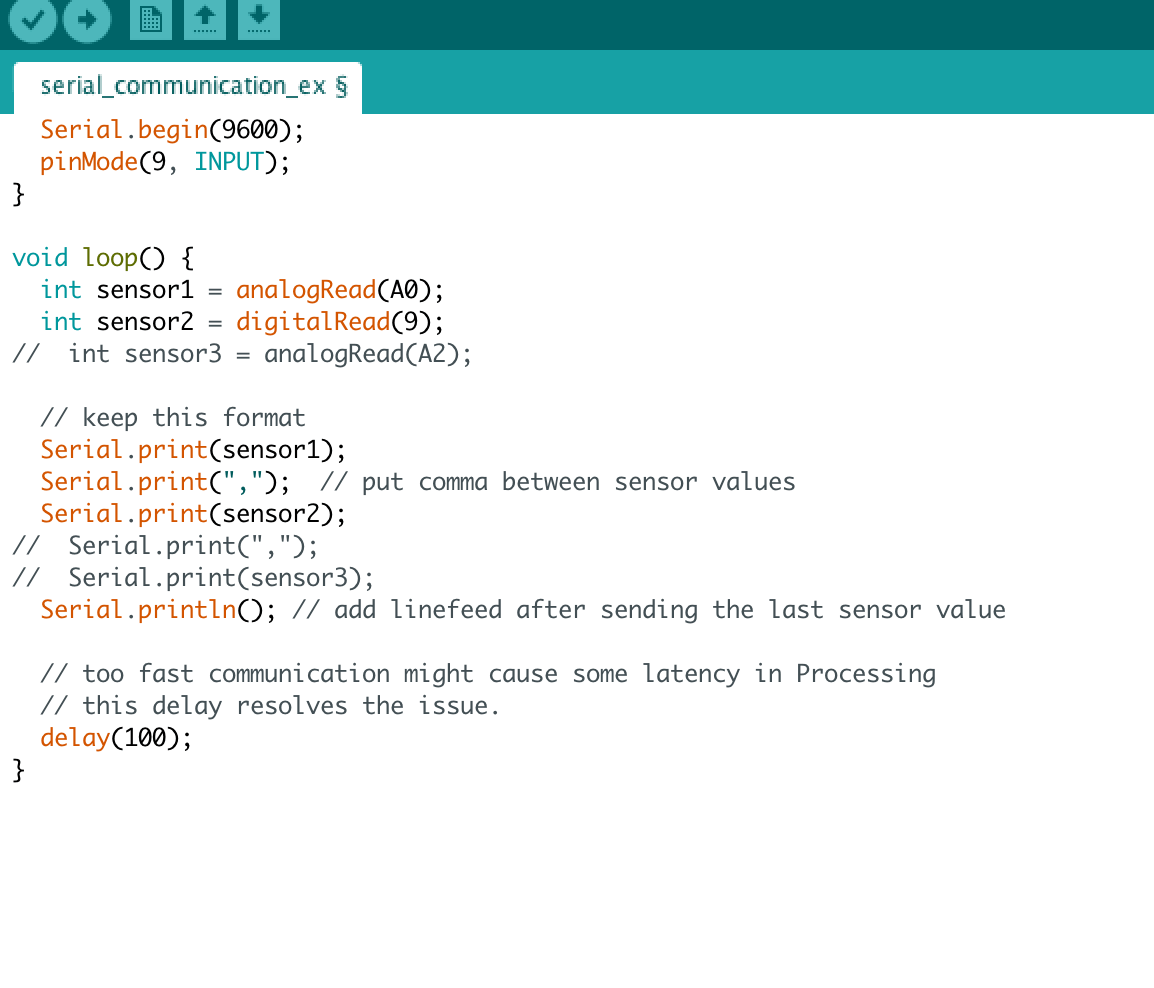
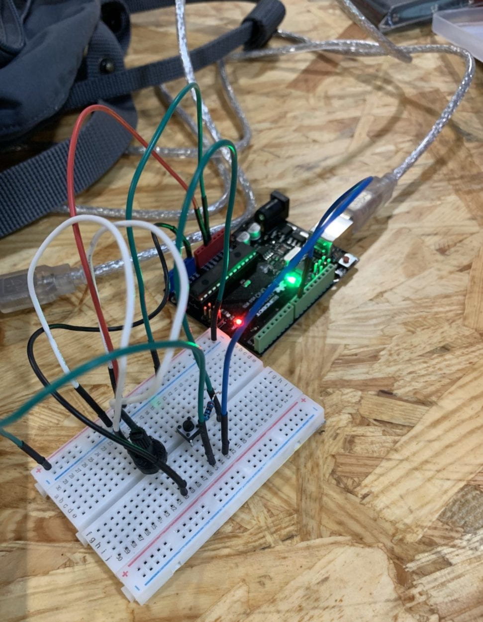
In the serial communication workshop, we first worked on an Arduino to Processing example using a potentiometer, a mini pushbutton switcher, and a resistor. We were to use the potentiometer and button on Arduino to control the location of an ellipse and the size of an ellipse on Processing, respectively. For this, we used the serial_multipleValues_AtoP example, modifying the second analogRead to read digitalRead and removing one Serial.print input. Then, we assembled the circuit with the potentiometer, button, and a resistor. We used float posX to designate the position of the values.

Arduino Code:

Processing Code:

import processing.serial.*;

String myString = null;
Serial myPort;


int NUM_OF_VALUES = 2;   /** YOU MUST CHANGE THIS ACCORDING TO YOUR PROJECT **/
int[] sensorValues;      /** this array stores values from Arduino **/


void setup() {
  size(500, 500);
  background(0);
  setupSerial();
}


void draw() {
  updateSerial();
  printArray(sensorValues);
  
  background(0);

  // use the values like this!
  // sensorValues[0] : pot 0 ~ 1023
  // sensorValues[1] : button switch 0, 1

  // add your code
  float posX = map(sensorValues[0], 0, 1023, 0, 500);
  int size;
  if (sensorValues[1] == 0) {
    size = 50;
  } else {
    size = 200;
  }
  ellipse(sensorValues[0], 300, size, size);
}


void setupSerial() {
  printArray(Serial.list());
  myPort = new Serial(this, Serial.list()[3], 9600);
  // WARNING!
  // You will definitely get an error here.
  // Change the PORT_INDEX to 0 and try running it again.
  // And then, check the list of the ports,
  // find the port "/dev/cu.usbmodem----" or "/dev/tty.usbmodem----" 
  // and replace PORT_INDEX above with the index number of the port.

  myPort.clear();
  // Throw out the first reading,
  // in case we started reading in the middle of a string from the sender.
  myString = myPort.readStringUntil( 10 );  // 10 = '\n'  Linefeed in ASCII
  myString = null;

  sensorValues = new int[NUM_OF_VALUES];
}


void updateSerial() {
  while (myPort.available() > 0) {
    myString = myPort.readStringUntil( 10 ); // 10 = '\n'  Linefeed in ASCII
    if (myString != null) {
      String[] serialInArray = split(trim(myString), ",");
      if (serialInArray.length == NUM_OF_VALUES) {
        for (int i=0; i<serialInArray.length; i++) {
          sensorValues[i] = int(serialInArray[i]);
        }
      }
    }
  }
}

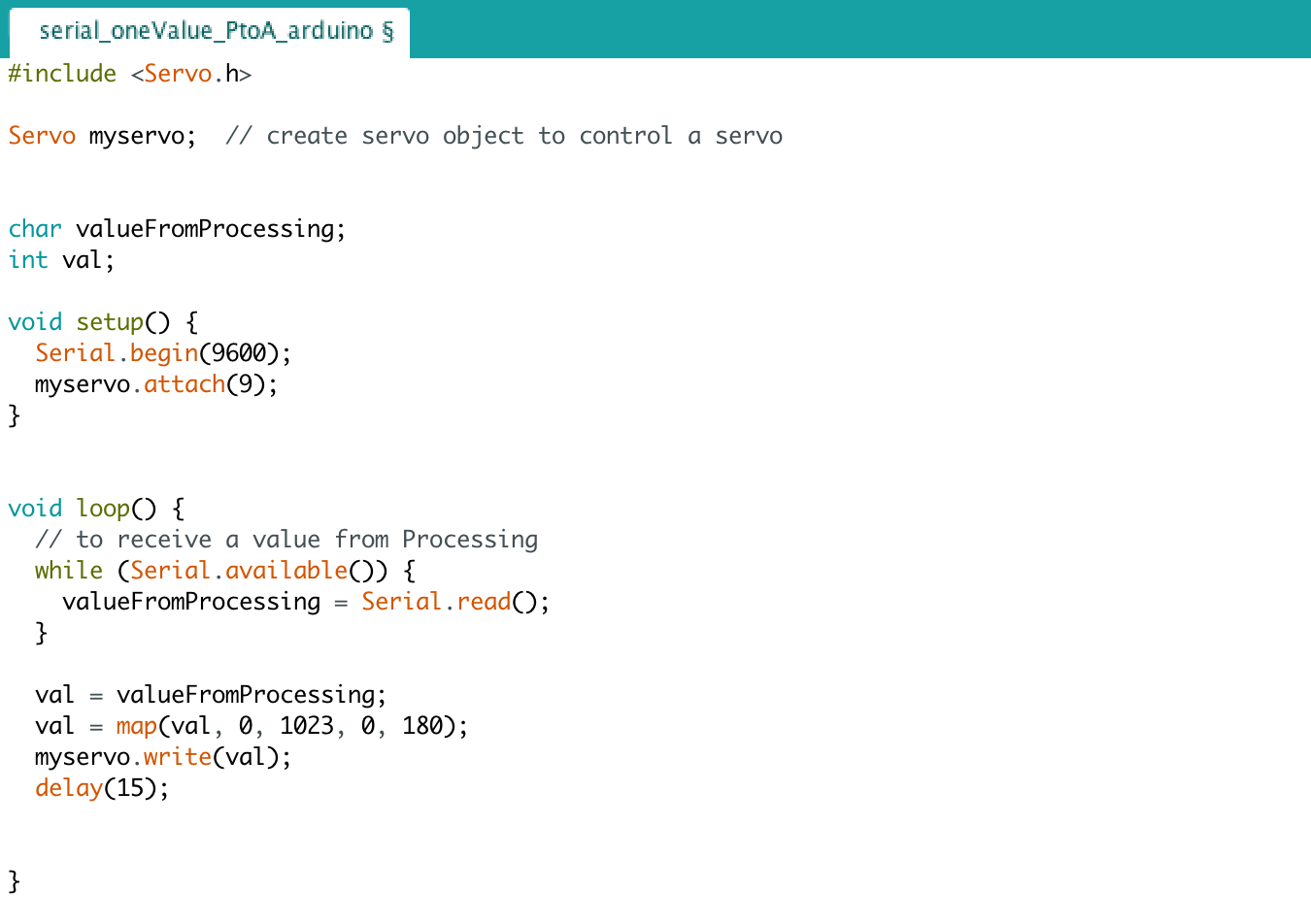
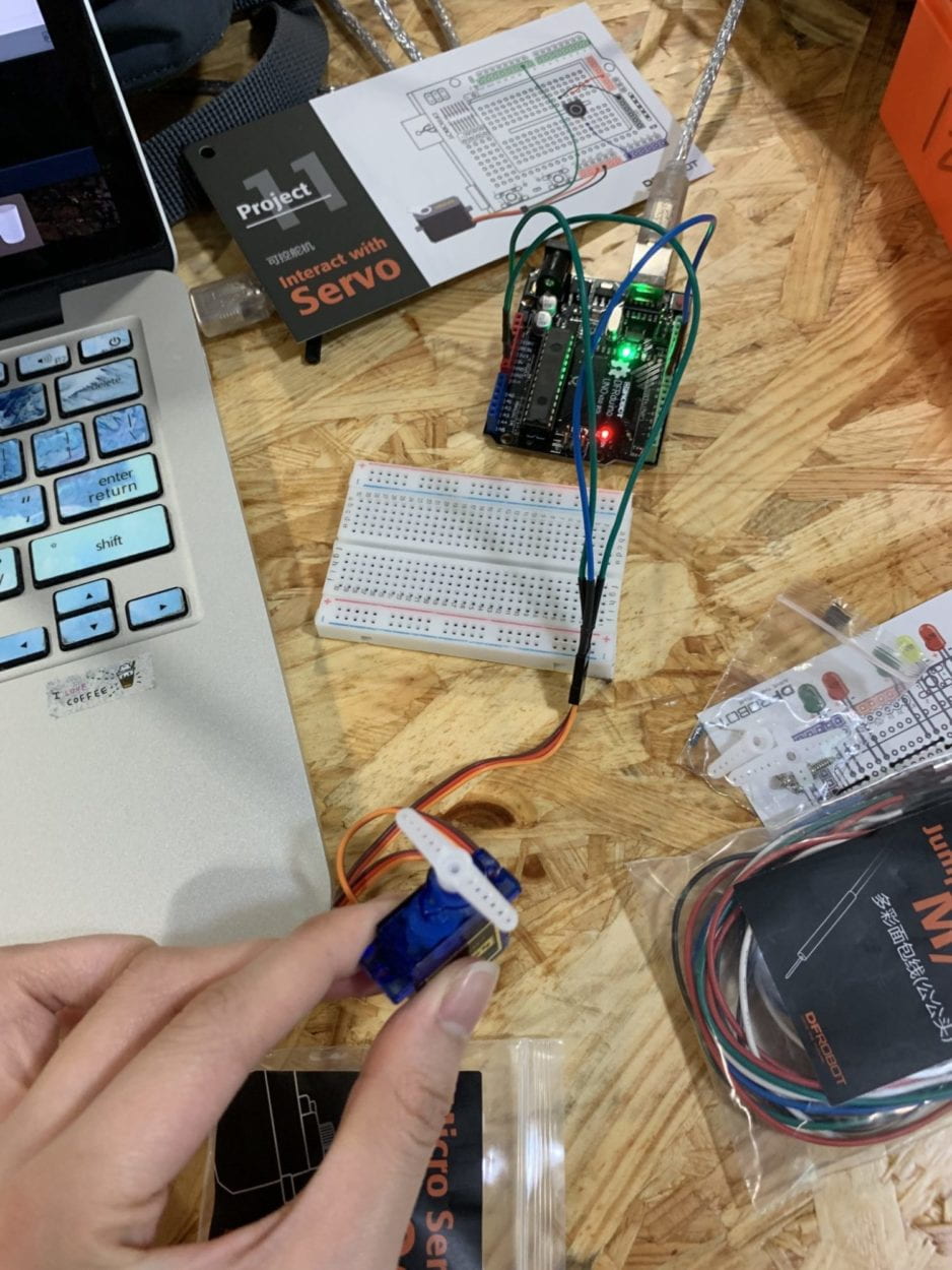
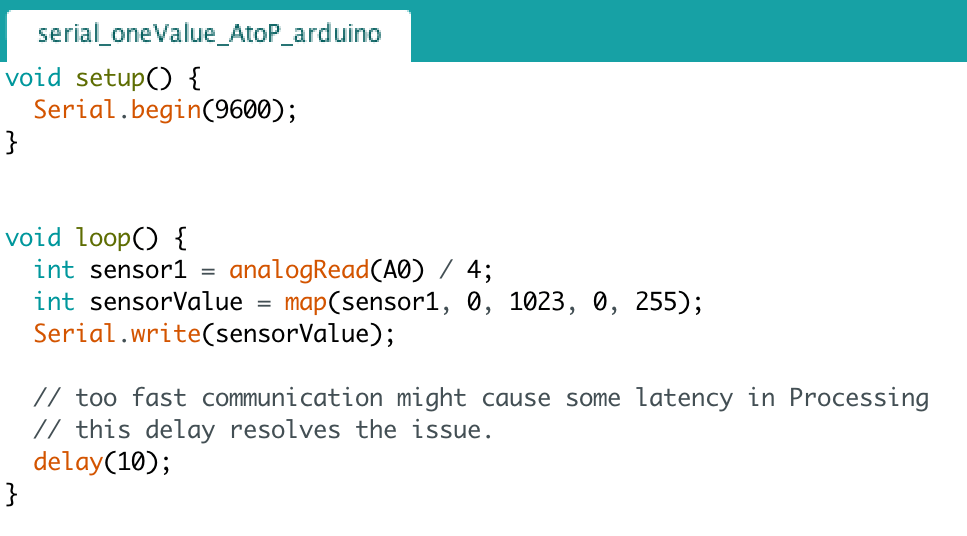
For the second example, we were to use a mini servo motor to be controlled by the keypad being pressed. For this, we used the serial_oneValue_PtoA example to read the input from Processing to Arduino. By pressing the keypard, the servo motor moves in response to its input. 

Arduino Code:

Processing Code:

import processing.serial.*;

Serial myPort;
int valueFromArduino;


void setup() {
  size(500, 500);
  background(0);

  printArray(Serial.list());
  // this prints out the list of all available serial ports on your computer.
  
  myPort = new Serial(this, Serial.list()[3], 9600);
  // WARNING!
  // You will definitely get an error here.
  // Change the PORT_INDEX to 0 and try running it again.
  // And then, check the list of the ports,
  // find the port "/dev/cu.usbmodem----" or "/dev/tty.usbmodem----" 
  // and replace PORT_INDEX above with the index number of the port.
}


void draw() {
  // to send a value to the Arduino
  if (mousePressed) {
    myPort.write(mouseX);
  } else {
    myPort.write(0);
  }
}

Recitation 9 Documentation

For recitation 9, we were to use Processing to manipulate a form of media, either an image or a video, with a physical controller corresponding with Arduino. Using the given code from the examples, we modified the code from the 01_oneValue_arduino_to_processing to correctly communicate the code from Arduino to Processing’s media output.

Using the functions pushMatrix() and popMatrix() from this week’s classes, I was able to make the image move and interact with the potentiometer from Arduino. These two functions allowed the image to be transformed, with pushMatrix() saving the current coordinate system to the stack, while popMatrix() restored the prior coordinate system. This allowed the image to jump from one place to another, in conjunction with the media processing from Arduino. 

Since I only used one potentiometer to control the input of the image, Arduino only reads one value to Processing. Ergo, I used the oneValue_arduino_to_processing example from our classes. I incorporated analog input via Arduino through the use of a potentiometer, then serially connected Arduino to Process to manipulate an image of my hamster. The potentiometer would adjust the image size by twisting it, reading the variables as an analog value and sending the input values as output values in Proccesing. 

Code for Processing:

import processing.serial.*;

Serial myPort;
int valueFromArduino;
PImage img1;
color mouseColor;
float mouseR, mouseG, mouseB;

void setup() {
  size(600, 600);
  img1 = loadImage("hamster.jpg");
  background(126, 137, 155);

printArray(Serial.list());

  myPort = new Serial(this, Serial.list()[3], 9600);
}


void draw() {
  while ( myPort.available() > 0) {
    valueFromArduino = myPort.read();
  }
  println(valueFromArduino);
  pushMatrix();
  translate(0, 0);  
  rotate(radians(map(valueFromArduino, 0, height, 0, 500)));
  
  image(img1, 100, 100, width/(valueFromArduino+1), height/(valueFromArduino+1));
  popMatrix();
  mouseColor = img1.get(mouseX, mouseY);
  mouseR = red(mouseColor);
  mouseG = green(mouseColor);
  mouseB = blue(mouseColor);
  println(mouseR+" "+mouseG+" "+mouseB);
  set(width/2, height/2,mouseColor);
}

Code for Arduino:

This week’s reading, Computer Vision for Artist and Designers, discussed the scope of applications that modern computer vision technologies has, especially in the field of military and law enforcement. But in recent years, an increase in the use of non-traditional computer programming applications such as Processing has contributed to the rise of a visual focus in the electronic arts and visual design communities. By using Processing, we are able to focus more upon the visual elements within coding, and therefore able to explore a multitude of technologies in order to execute such projects. Particularly in this recitation’s project, we used technology to serially connect images within physical hardware. Processing allows us to execute machine vision techniques within a digital environment, as it is extremely well­ suited to the electronic arts and visual design communities (Golan et al., 7). This application can be expanded into much more expansive projects that similarly connect media input and output, with these tools commonly seen “to create art installations, performances, commercial kiosks, and interactive industrial design prototypes” (Golan et al., 7). TeamLab Borderless’ exhibit is one such example, in which technology allowed for a much more visually emphasized production rather than the coding behind it.

Final Project Essay

A. The Labyrinth Maze

B. PROJECT STATEMENT OF PURPOSE

Based on our task to create an ongoing, interactive experience using Processing and Arduino, I aimed to create a device that would engage the user and would provide for a fun gaming experience. Inspired by traditional corn mazes and labyrinths mazes, the intended audience for this device would be anyone aiming to challenge themselves through utilizing strategic forms of strategizing a way to solve a complex maze. The maze could additionally boost the user’s patience and persistence level, whilst improving their hand-eye coordination and concentration levels. I seek to address the challenge of successfully combining virtual projection upon a physical object, in which its complexity challenges the player in completing the challenge. I hope for the device to cause the user to strengthen their cognitive thought processes and heighten their abilities of problem solving. 

C. PROJECT PLAN

I plan to create an interactive one-player game, with the physical labyrinth placed on top of a surface that would allow for it to rotate. The player would utilize a joystick in order to tilt the surface of the maze, wherein a marble would navigate the paths of the labyrinth. The marble would act as the physical “player” in the game, starting from the point of entry to the point of exit, while navigating various “obstacles” throughout the challenge. The obstacles would be virtually projected through Processing, through projecting an image onto the physical maze. For the first week, I will first create a cardboard prototype of the physical maze, that would include the maze and the walls surrounding it. I would additionally work on the Processing image for the projection, utilizing Photoshop to draft an image of a maze with its obstacles integrated throughout it. I would Photoshop a visual of a complex maze for the player to solve that would act as the physical labyrinth. For the second week, I would work on the codes that would connect the hardware and joystick to Arduino, and that would also connect the image in Processing to the maze. I would additionally work out the details of the projection through Processing, and making sure it would correspond to the physical maze smoothly. I would utilize the laser cutting for the box and prepare the materials for the maze, including the joystick, marble, and a smaller-scale projector. For the third week, I would finalize the design and assemble the materials together, while focusing on ensuring the final design would hide the wires and hardware of the game. 

D. CONTEXT AND SIGNIFICANCE

Inspired by these wooden labyrinth games, this project would be highly reliant on the user’s input in order to work successfully. They would have to play the game and focus on navigating the marble throughout the maze from one point to the other, making for a continuous loop of interaction between the user and the device. Similar to a conversation, interaction can be closely defined as “a cyclic process in which two actors alternately listen, think, and speak,” as outlined in The Art of Interactive Design (5). For a continuous loop to occur, the user needs to be constantly using and interacting with the device, as the device responds to the user’s endless input. This sequence consists of three steps:  input, output, and processing, as outlined in Introduction to Physical Computing (Igoe & O’Sullivan, 20). This device closely aligns with interactivity, as the player is constantly giving input through using the joystick to rotate the maze, while the device is moving the marble for the player to navigate the pathways. After successful completion, the project may lead onto more advanced mazes, including adding levels of difficulty or an increased number of obstacles for the player to navigate.