Recitation 4: Drawing Machines by Karen Zhang

Partner: Anna Shi

Material:

1 * 42STH33-0404AC stepper motor

1 * SN754410NE ic chip

1 * power jack

1 * 12 VDC power supply

1 * Arduino kit and its contents

2 * Laser-cut short arms

2 * Laser-cut long arms

1* Laser-cut motor holder

2 * 3D printed motor coupling

5 * Paper Fasteners

1 * Pen that fits the laser-cut mechanisms

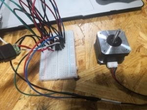
This week we need to build a drawing machine step by step. We recognize that there may be potential damage to our computer if we did not build the circuit properly.
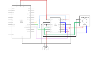
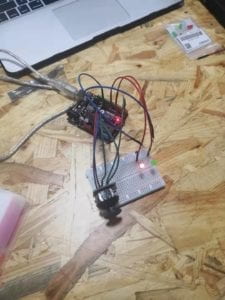
Step one was much easier than I previously thought. Even though the schematic diagram was complicated at first sight and it took me a long while to figure out which one is connected to which one, I didnā€™t run into any problems the end.

Step two needed us to add a potentiometer into the circuit. However, at first I completely forgot how to connect the three legs of the 10k potentiometer to their matching access port. After teaching by the instructor, I realized three of them should connect separately to the ground, power, and input. Besides, I also had some problems with the code since I think I am still not familiar enough with the function ā€œmap()ā€. But the issue with the code was solved quickly.

Overall, step three is the most interesting part!! Basically, we assembled different components altogether with my partner. It was not a difficult process, but we did find a problem since the pen could not keep touching the paper constantly. So we had to put something under the paper to lift it up, and the pen didnā€™t seem to be in our control all the time.

Question 1:

What kind of machines would you be interested in building? Add a reflection about the use of actuators, the digital manipulation of art, and the creative process to your blog post.

Since we just built the drawing machine in our recitation, it reminds me of how I hate washing the brushes and palette when I learned watercolor and Chinese calligraphy when I was small. Especially in the winter, the water is so cold and you donā€™t even want to touch the cold water. So I plan to invent a machine which can wash and dry any brushes you want. Humid and temperature sensors may be needed to test whether the brush is clean and dry. A motor can rotate the brush quickly. The 3D print is also needed to create the shell.

Question 2:

Choose an art installation mentioned in the reading ART + Science NOW, Stephen Wilson (Kinetics chapter). Post your thoughts about it and make a comparison with the work you did during this recitation. How do you think that the artist selected those specific actuators for his project?

I choose Douglas Irving Repetto, Gaint Painting Machine/San Mateo to compare with the work I did in the recitation. The reason why I choose this project is due to the similarity. We both somehow create a drawing machine, however, this one is much bigger and more flexible than the one we built. Another thing surprises me is that they paint on transparent Mylar, I think it is so cool! Compared with our drawing machine, a lot of work should be done to control the machine to adjust the speed and direction of the motors.

Recitation 4: Group Project by Karen Zhang

Definition of interaction

In my opinion, interaction must involve two actors in a cyclic process with thinking, processing, and responding. Besides, I think interaction must have inputs and outputs, and interaction has to be able to process complex information instead of a simple one, which ultimately differs interaction from an instant reaction. And reading ā€œThe Art of Interactive Designā€ written by Chris Crawford helps me most to define what interaction is. Creating an interactive project by myself also helps me to understand better about interaction.

Two projects from websites

The first project I select shows that it does not align with my definition of interaction. The street art/public art in the streets of Detroit make citizens engage with the city itself. And I cannot deny that. Quote from the original article – “We wanted to keep people engaged,” says Curis of the project, “and wanted to figure out a way to have people come [ to the area] for not just the visual arts but music, culinary, and performance, too.ā€œā€ However, simply stopping and watching are not interaction. The meaning behind it is just shallow. I think interaction should process complex information. In my eyes, this interaction is not deep enough.

(https://www.vice.com/en_us/article/qvv3qp/massive-murals-detroit-library-street-collective)

Moreover, the second project which I choose aligns with my definition of interaction. This project is called Expressive Tactile Controls created by Hayeon Hwang. By pressing the button, the project indicates each individualā€™s unique personality and they could express its emotion only through haptic feedback. And most importantly, this project involves with complex information to process.

(https://www.creativeapplications.net/member-submissions/expressive-tactile-controls/)

Our group project

The first step is always the hardest. Our group gathered together and listed all the problems we could think about in 2119. We listed disability, obesity, environment, and so on. But we did not know how to start and where to start. We stayed at this stage for a really long time, until Celine come up with the idea of magical gloves.

We have this idea since sign languages are hard for normal people to understand. Imagine someone ā€œtalkingā€ with you by sign languages but you have no idea what he is ā€œtalkingā€ about. The visibility of sign languages works invisibly to others. Due to the complexity of sign languages, people generally have a hard time to understand it. So what we do is to use sign languages ā€œvisible!ā€ Maybe it feels weird to you that I use the word ā€œvisibilityā€ or ā€œvisible.ā€ What we want to do is to let people with disabilities to be heard, reveal your voice!! To let others understand, there are two actors involved in the interaction. The gloves deal with complex information from the sign language and reflect it back to the other, so this person can understand what the mute person just said.

Our group thinks the idea is much more important than making the product perfectly. We use these transparent gloves as our prototype. The first half of our performance we show how hard it is for you to grow up if you cannot speak. We also design the process of language output in our performance. We want to show that people from different countries are all welcomed to use this product.

Here is our poster!

Recitation 3: Sensors by Karen Zhang

Partner: Anna

Introduction:
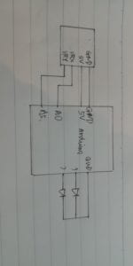
In the third weekā€™s recitation, we chose one of the listed sensors, built a circuit and interact with the sensor. So I chose joystick, but it looked harder than we thought to let it work. First, there was something wrong with the website link so we were unable to find the code. Second, the Joystick module comprised of two potentiometers which gauge motion along the x and y axis, and a pushbutton for the z axis. Because of this composition, it can be interfaced with Arduino just as if it were two potentiometers.

Here is our code:

// Arduino pin numbers

const int SW_pin = 2; // digital pin connected to switch output

const int X_pin = 0; // analog pin connected to X output

const int Y_pin = 5; // analog pin connected to Y output

int ledPin_1 = 9;

int ledPin_2 = 7;

int X = 0;

int Y = 0;

void setup() {

 pinMode(SW_pin, INPUT);

 digitalWrite(SW_pin, HIGH);

 pinMode(X_pin, INPUT);

 pinMode(Y_pin, INPUT);

 pinMode(ledPin_1, OUTPUT);

 pinMode(ledPin_2, OUTPUT);


 Serial.begin(115200);

}

void loop() {

 Serial.print(“Switch:  “);

 Serial.print(digitalRead(SW_pin));

 Serial.print(“\n”);

 Serial.print(“X-axis: “);

 Serial.print(analogRead(X_pin));

 Serial.print(“\n”);

 Serial.print(“Y-axis: “);

 Serial.println(analogRead(Y_pin));

 Serial.print(“\n\n”);


 X = analogRead(X_pin);

 int mappedValue = map(X, 0,1023,0,511);

 if(mappedValue > 205) {

   digitalWrite(ledPin_1, HIGH);

 }else{

   digitalWrite(ledPin_1, LOW);

 }

 Y = analogRead(A5);

 int mappedY = map(Y, 0,1023,0,511);

 if(mappedY > 205) {

   digitalWrite(ledPin_2, HIGH);

 }else{

   digitalWrite(ledPin_2, LOW);

 }

 delay(500);

}

At first, we connected the circuit, but the joystick did not work. After checking again, we found that we forgot we should use Serial.begin(115200) instead of using the normal Serial.begin(9600). After we fixed that problem, the joystick still did not work. We asked the instructor for help, and we realized that we made a silly mistake – we created a short cut. After solving this problem, the joystick finally worked! In the video, the green LED did not light very brightly. But if you looked carefully, you will notice the difference.

Question 1:
What did you intend to assemble in the recitation exercise? If your sensor/actuator combination were to be used for pragmatic purposes, who would use it, why would they use it, and how could it be used?
I did not think specificly what I want to assemble in the recitation. I chose joystick since it is the most interesting sensor. By moving the joystick, the brightness if the lights change. I think it may be used in video games and let children play with it.


Question 2:
Code is often compared to following a recipe or tutorial.  Why do you think that is?I think it is definitely true! The code is compared to following a recipe or tutorial to intruct the computer. Both code and recipe/tutorial are written in an certain format, so it can be correctly followed. And the code is a bridge for people to communicate with the computer.

Question 3:
In Language of New Media, Manovich describes the influence of computers on new media. In what ways do you believe the computer influences our human behaviors?

In todayā€™s world, the computer has a strong impact on human behaviors. We heavily rely on technology. We became lazy since the computer can help us memorize things and deal with small things in our daily life. The computer has simplified the way humans think and act. The computer allows us to communicate with people from long distances. However, it also reduces our physical contacts with each other

Recitation 2: Arduino Basics by Karen Zhang

Partner: Anna Shi

Introduction:

In the second weekā€™s recitation, we started to learn how to use Arduino and used Arduino to build circuits. Based on last weekā€™s recitation, my partner and I found the first two circuits were pretty easy for us. We finished them one time, but the third one was too difficult and we made lots of mistakes. The third circuit wasted us so much time, and we do not have time to build the fourth circuit.

Circuit 1: Fade

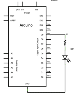
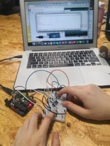
Since we had the schematic and we had practiced building circuits before, we only tried once and the first circuit worked. However, there were still two things that we needed to think carefully. First, make sure all the components are connected to the breadboard. Second, remember to upload Arduinoā€™s code on your laptop! These two things are really simple but easy to forget.

Circuit 2: toneMelody

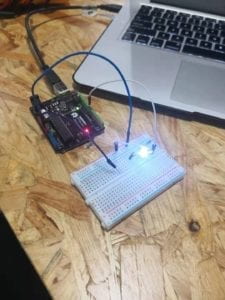
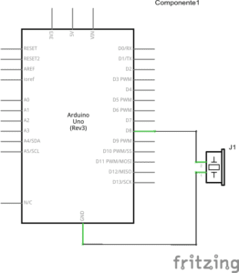
Like the first circuit, we did encounter any problems. Based on the first circuit, we made a few changes to it, then put our speaker on the breadboard. The speaker started to make its noise.

Circuit 3: Speed Game

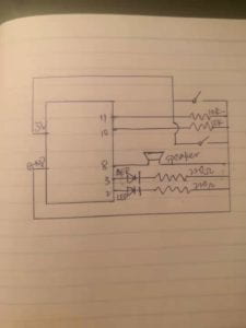
The third circuit was much much more difficult than the first two. First of all, we encountered a problem with resistors. We did not know which resistor on the schematic was 220 ohm or 10k ohm. We started to look at the number and color of loops on the resistor to differentiate them, so we spent a lot of time trying to figure out the resistors. But we found out later, by logging into the website and clicking the resistor, we could found out which resistor was on which part. Then, we quickly built our circuit but it did not work. By checking it again and again, we found we might accidentally put the LED light in the wrong place. The longer leg of LED should connect to the hole on the breadboard next to it. And we used so many wires, the wires also caused us a problem to find and fix the problem. Finally, we thought the circuit could work now. But the answer was no! We found Player 2 always won, we tried again and again, something was wrong with Player 1. We asked the instructor for help, we examined it for a long time. Then, the instructor suggested we could change the button and gave it a try. Then we did, and it worked! Plus, the schematic may not be right. 

Question 1:
Reflect how you use technology in your daily life and on the circuits you just built. Use the text Physical Computing and your own observations to define interaction.

When I think about technology in my daily life, the first thing I come up with in my mind is my smartphone. It helps me to access to multiple things I do in my daily life. And I use my laptop to finish all my homework. Technology is strongly involved in our daily practices. In this weekā€™s reading ā€œIntroduction to Physical Computingā€, physical computing entails the ā€œcreation of a conversation between the physical world and the virtual world of the computer.ā€ Physical computing can create interactions between the physical world and the virtual world. By using physical computing, we find we can create the fading light, the sound from the speaker, and even a game that you can play with your friend.

Question 2:
If you have 100,000 LEDs of any brightness and color at your disposal, what would you make and where would you put it?


As a social science student, I think we should give LEDs to children worldwide who donā€™t have enough light to study at night. But I understand this is Interaction Lab. As my friend proposes, I think I want to build a house with all LEDs of any brightness and color and make my own exhibition in many cities šŸ™‚

Karen Zhang ā€“ Documentation ā€“ Recitation 1: Electronics & Soldering

For last weekā€™s recitation, students were expected to build three different circuits and learn how to solder. Here is a list of components we used in the circuits.

Components :

Breadboard: it provides a base for making electronic connections

LM7805 Voltage Regulator: it is designed to automatically maintain a constant voltage level

Buzzer: when it is connected, it can make a buzzing noise

Button: it is used to interrupt or connect the flow of current through a circuit

220 ohm Resistor: it can add resistance to the circuit to decrease the voltage
LED: it lights when it is connected!

100 nF (0.1uF) Capacitor: used to stabilize and smooth the flow of electricity

Barrel Jack: it connects the power supply with the breadboard.

10K ohm Variable Resistor (Potentiometer): its resistance can change


Multimeter: it can measure electric current, voltage, and resistance. And we use it to measure the resistance.

Several Jumper Cables (Hook-up Wires): it is used to connect different electrical components.

Circuit 1

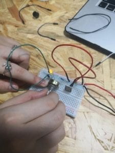
I think it takes me a long time to figure out how to build the first circuit. The first part we get confused is how to use the breadboard. After being taught by instructors, this problem was soon solved, and my partner and I started to build the circuit.
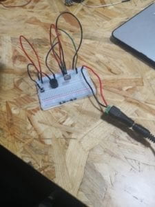
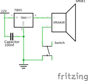
For Circuit 1, we connected all the necessary components, but the bell did not ring. We guessed that there was something wrong with the capacitor since that is the last part we put on the breadboard. By examing the circuit again, we found out that we did not need so many wires to connect, just directly connect the capacitor on the left side of the breadboard, the problem is solved! Also, the lesson I learned from this failure is that do not use so many wires! It could make your work more complicated and much harder to find out what was wrong.


Circuit 2

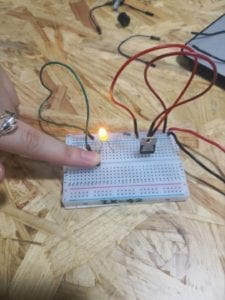
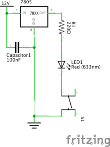
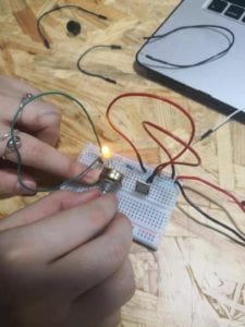
 Making the second circuit is much smoother than the first one. However, when I pressed the button, the lamp did not light. We could not find the reason why. After checking the circuit again and again, we believed that we perfectly connected each component. Then, another instructor pointed out our problem, why donā€™t you guys check the LED again? And we just realized we connected the LED is an opposite direction. The longer leg should be connected to the resister, and the shorter leg should be connected to the switch. 

Circuit 3

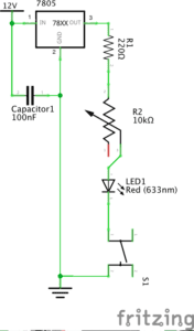
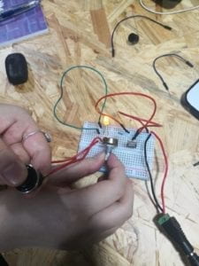
Based on the previous lessons we had, the third circuit is finished one time. We used the variable resistor to adjust the brightness of the light. 

Then my partner and I went to soldering stations to learn how to solder. We need to connect two wires with the switch together. Tan the tip, then melt and put solder into the joint, the solar having a lower melting point than the adjoining metal. We waited for it to cool down, so the wires and switch could tightly connect. Overall, it is an easy task. However, it could be tricky at first to put the melting solar to the right position precisely at the joint.

On the left of this picture, it is the new switch we made by soldering the wires

Answers to Questions

Question 1:
After reading The Art of Interactive Design, the circuits we built all include interactivity. In my opinion, there are two actors in the interaction. The circuits are built to illustrate the interactivity between what we built and us. It acts like communication that we have. As I press the button or turn the variable resistor, the lamp and bell respond to me. The ringing of the bell and the lighting of the lamp both show the interactivity.

Question 2:
From Zack Liebermanā€™s video, I think that adding physical computing technologies to art can actually make drawing more interesting and interactive. Lieberman presents three examples in the video and shows us how interactive art is created by computing and design. I am particularly interested in the third example. He used the simple eye-tracking system and allowed disabled artists to draw graffiti using their eyes. And it all relied on the technology(physical computing), which makes it all happen.