Dreamie Beanie – Lana Henrich, Week 4

Interactive Group Project; Week 4

Research

Interaction is when different things communicate with each other in order to achieve a goal. With reference to technology, interaction between humans and technological devices is the two working together, usually with the person triggering a certain response from the computer, in order to evoke a specific, predisposed outcome.

Project 1

Anti-Drawing Machine – Whimsical and imperfectly characteristic collaborator

I like this project because it exemplifies a direct interaction between a person and technology; someone drawing directly triggers the paper to move based on their hand motions, and the user is able to see and enjoy a finished project (their drawing) at the end, which was created as a collaboration between the person drawing and the machine.

Project 2

Open Highway – Surfacing the hidden layers of the city

I don’t like this project because the actual user who gets to see and experience the installation isn’t the person triggering the light response. I think of interaction as a user being able to cause an action and then be able to see or in some way sense the triggered response. In this project, the people driving the cars which trigger the lights don’t get to actually see the lights (since they are in the car on the highway).

Our Project- Dreamie Beanie

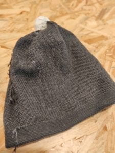
The idea we came up with for our project is a ‘beanie’ hat which can be worn during sleep and then record, animate, and analyze someone’s dreams. The hat itself is infused with sensors which pick up and record the neurological signals that shoot through the cortex of the brain during dreaming. The ‘pom pom’ at the top of the beanie is the storage device for these signals, and codes   the information into a language which can be connected to a computer or screen, that then processes the code and creates an animated ‘movie’ of the dream. After watching the video representation of their dream, one could send a sheet of the key parts to a professional oneirologist (psychologist specialized in the meaning behind dreams) to receive an analysis of what the dream subconsciously reflects about the person’s state of mind and thoughts.

Our projects responds to my earlier critique of Project 2 because there is direct interaction between the user (person dreaming) and the machine (the beanie). The dreams of the person wearing the beanie interact with the technology installed in our project, and there is an end product (the animated video and analysis) which the user can enjoy, and which was created by an interaction between the person and technology.
Joystick – LED Interaction Circuit: Week 3, Lana Henrich

Week 3 Recitation

Circuit Building Process

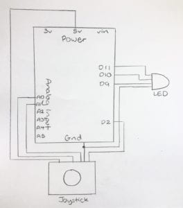
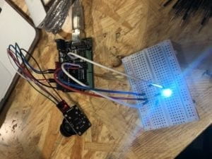
For this week’s recitation, my partner Kyle and I chose to work with the joystick module. Our original idea was to create a circuit with which we could use the joystick to control the color of an LED. When we saw how the data on the serial monitor changed depending on which direction the joystick was moved in, we hoped to build a circuit connection in which each direction the joystick was moved in would make the LED turn a different color.  We used the flash cards that were in our kits as the basic foundation of our circuit. We tried out a number of different preset codes that were available on Arduino, including Fade and Blink. Professor Rudi helped us find a code online which we could build off of to create the code for our circuit. Because we wanted to make the LED change color according to the data inputted by the joystick movement, we had to map the analog input and create and “if” “then” code which would connect the joystick input to the LED output. Completing the circuit and finishing this code was the most complicated thing we had done in this class thus far, and we utilized the entirety of class time to complete it. After a series of trial and errors, we were able to successfully finish the circuit.


Question 1

We intended to assemble a circuit in which the movement of a  joystick controlled the color of an LED. With respect to pragmatic purposes, our circuit could be used in an interactive art exhibit, in which viewers can change the color of the LED’s used to assemble it. Otherwise, our circuit could also be used in a home or work setting, where the color of lights/lamps can be adjusted according to the event, situation, or outdoor lighting (like from cool to warm lighting).

Question 2

A circuit I use in my daily life is turning the lights in my dorm room on/off. My circuit could be integrated into this interaction so that I could change the lighting in my room from cool to warm/vice-versa, perhaps making the light cooler when the warm light of the sun is shining through the window, and warmer when there is no external light source.

Question 3

Code is similar to following a recipe/tutorial because, when writing a code, you have to take very specific steps in a very specific order in order to successfully complete it. There are certain terms which are used in code which have to be integrated into the coding process, just like how a tutorial outlines certain terms and steps which need to be taken.

Question 4

Computers make humans less independent by giving them an easy option for solving mathematical problems and answering questions, which would otherwise need to be figured out by one’s own mind or through extensive physical research. Given this, however, computers also expedite human behaviors by making them more efficient; whenever there is something someone doesn’t know, they don’t have to go through a time-consuming trial and error process, but can instead just look it up on the internet.

Recitation 2: Building Circuits by Lana Henrich

Recitation Week 2: Building Circuits

Circuit 1 – Fade

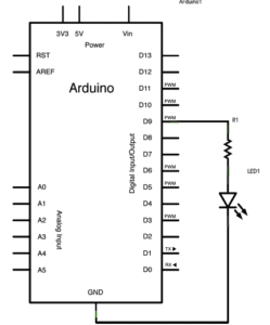
Building this first circuit went very smoothly for us, as we built similar circuits in the first week’s Recitation. Looking at the diagram, we connected the necessary cables to the breadboard and the LED, and were able to quickly finish building the circuit. Following this, we loaded the code onto the Arduino program, and the circuit worked properly. Compared to last week’s circuits, building this one was a lot easier for us, as we were very comfortable with the materials and knew right away what we had to do to get started.

Circuit 2 – toneMelody

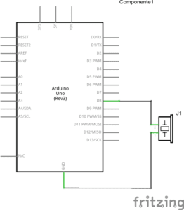
Building this circuit was also relatively easy for us, as we had worked with a buzzer before in the previous recitation, and the code was already written out for us on Arduino. This circuit required only 2 jumper cables, and so we were able to finish building quickly and upload the code.

Circuit 3 – Speed Game

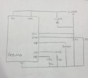
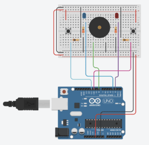
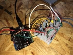
Building this last circuit took us a lot longer than building the other two, as this circuit required many different jumper cables, and multiple resistors, buttons, and LEDs. It was a bit hard for us to read the diagram, as the labels of the ports were written very small and a lot of cables required connection from different points around and to the breadboard and Arduino board. Although it took us a while to correctly place all the cables and keep tracking of everything we already put into the circuit, we were nevertheless able to get the circuit working on the first try. It was actually very fun to play the game which we uploaded onto the Arduino, as all parts worked smoothly every time we played. Drawing the diagram after building a circuit was also a bit of a challenge, as there are so many connecting parts and points vital to the circuit. This was the most challenging circuit we had gotten so far, and though it looked intimidating at first, it proved to be easier than expected, though it was a bit time-consuming.

Question 1

Interaction is the communication between humans and technology, wherein people trigger certain responses from technological devices through specific actions. For example, when someone uses a smart phone, they can touch (interact with) with the screen in order to cause a certain response, such as the opening of an application.

Question 2

The inputs I recognized were the buttons, the arcade buttons, and resistors. The outputs I recognized were the speaker and LED lights.

Question 3

If I had 100,000 LED’s, I would create a wall display on which the LED’s can light up at different times and in different colors in order to create moving images and patterns (such as a wave crashing down or a silhouette of a person walking). This display could go in an art museum, and have a tablet set up where people can select the images they want to be created by the lights.

Question 4

By image I.1 in the Physical Computing reading, I can understand that interaction with technology is limited to what part of the computer we can physically interact with. A computer can only “see” the parts of us we use to interact with it, such as our fingers (to type). Even technological devices like muscle sensors are limited to only what parts of ourselves we connect to the device. Further advanced technologies, such as eye trackers, also have specific algorithms and codes that they follow which allow them to work; meaning our interactions with them are limited to what the devices have been pre-programmed to do. While humans have the ability to form and perform infinite thoughts and actions, technology can only do what it is taught, and cannot think for itself.

Recitation Week 1 | Lana Henrich

Recitation Week 1

Materials

Breadboard:a layout of conduc

tive terminals that provides a consistent cable design for t

he construction of circuits

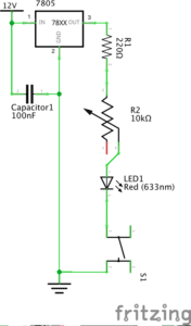
LM7805 Voltage Regulator:maintains a constant voltage level so the buzzer and LED can operate efficiently

Buzzer:an electrical device that makes a buzzing noise

Push-Button Switch:gives the interactor the power to choose when to let the current flow

Arcade Button:allows one to control whether or not electricity passes through the circuit by pressing the button

220 ohm Resistor:adds resistance to the circuit in order to decrease the voltage and keep the LED stable

LED:a semiconductor diode which glows when a voltage is applied

100 nF (0.1uF) Capacitor:stores energy in the form of an electrostatic field between its plates

10K ohm Variable Resistor (Potentiometer):a resistor with an adjustable voltage divider

12 Volt Power Supply:used to reduce the mains electricity at 240 volts AC down to 12 volts do make it more useable

Barrel Jack:a power connector used for connecting low-voltage devices to external electricity

Multimeter:measures electric current, voltage, and usually resistance

Jumper Cables (Hook-up Wires):a single insulated conductor used for low-voltage applications

Circuit 1:

Building Process

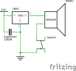
Building the first circuit was somewhat difficult, as we had to learn how to work with the layout of the breadboard and all our materials. We encountered the problem that we couldn’t identify which piece was which but were able to refer to the recitation notes to see a picture and function of each piece. Once we identified all the pieces and placed them in the correct circuit, we tried hitting the button, but failed to make the buzzer buzz. After receiving help from one of the teaching fellows, we realized one of our pieces was faulty, and replaced it with a new one. Upon this adjustment, the buzzer worked, and we were able to take apart the circuit and start the next one.

Circuit 2:

Building Process

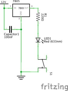
The process of building the second circuit went a lot smoother than the first, as we were more familiar with the materials and working with the breadboard. The only difference between circuit 1 and 2 is that we replaced with an LED light and added a resistor to tone down the voltage of the bulb. Because of this, we were able to reuse a lot of the previous circuit and did not run into issues while completing it.

Circuit 3:

Building Process

Building the last circuit went faster than building the other 2, although we did run into issues along the way. We did not understand the circuit diagram at first and were unable to place the pieces correctly into the circuit. Though circuit 3 was harder for us to complete than circuit 2, it was easier than circuit 1. All we had to do to complete this circuit was add the 10K ohm Variable Resistor to circuit 2 to be able to adjust the brightness of the bulb. At first, the LED would not turn on, so we once again asked a teaching fellow to assist with our issue. He then checked all parts of our circuit and it seemed to be correct, so we deduced that the problem lied in the reliability of the materials we used.

Question 1:

The circuits we built include interactivity because all parts of the circuit have to work together in order for it to perform the desired result. For example, in the third circuit, the resistor works with the capacitator and current flowing through the breadbox to make the LED work and stay stable. While the resistor dissipates energy, the capacitator stores it, which allows the circuit to function as desired and turn on either the buzzer or the LED when the button is pressed. By using wires and other materials that facilitate or alter the flow of energy, electrically charged particles can be passed on from unit to the next, thus having the components of a circuit working together towards a common purpose.

Question 2:                                                                                                                      

Physical computing can be used to “bring art to life”, as in the project shown by Zack Lieberman. It can be used to trick the eye into making otherwise lifeless or still images move and respond to cues triggered by the art’s audience, like in exhibitions in art museums that allow visitors to interact with and create their own art. Digitalizing art allows for a wide range of interactive possibilities, as coding allows for limitless possibilities for the creation of such artworks. Computing can allow artists to create things that would otherwise be physically impossible, such as drawing and projecting graffiti live onto a road using eye-tracking technology (shown in Liebermann’s video).