Serial Communication – Lana Henrich

Recitation Week 8: Serial Communication

Documentation

This recitation was a bit more chaotic than the past few. After plugging the Arduino into my laptop and tried connecting it to my port, I realized that I kept getting error messages on my Arduino program. This was similar to an issue I was having with my Arduino in class, but I thought I had fixed the issue by just continually taking out and re-plugging in my Arduino. After receiving help from multiple people during recitation in an attempt to solve the issue, it took about 40 minutes for us to figure out what was wrong, which was that my adapter is malfunctioning and only occasionally works with my Arduino and laptop (I have since ordered a new adapter, though it sadly has not arrived yet). While I was trying to figure out the issue with my Arduino, I was obviously unable to connect my Arduino to Processing, and thus started my code for the Etch-a-Sketch by coding an Etch-a-Sketch that did not require an Arduino, meaning a line would be drawn (made of ellipses) following the movement of the mouse. A video of this code in action is below:

Though I was able to figure out the issue with my Arduino connection, I sadly could not solve this, as my adapter was not working and I didn’t have one to use to complete the exercises. I did, however, finish wiring the Arduino and have pictures of my connections below:

Schematic

The interactions involved in the Etch-a-Sketch are composed of data being sent to each potentiometer and that then being sent to processing to draw lines. One potentiometer controls the x-value of the line being drawn, while the other controls the y-value.

My code for the Arduino + Processing Etch-a-Sketch is below:

import processing.serial.*;
import cc.arduino.*;

int varX;
int varY;
int xPin= 0;
int yPin= 1;

void setup() {

//println(h);
arduino = new Arduino(this, Arduino.list()[3], 57600);
colorMode(HSB);

size(1280,720);

varX= arduino.analogRead(xPin);
varY= arduino.analogRead(yPin);

}

void draw(){varX= arduino.analogRead(xPin);
varY= arduino.analogRead(yPin);

drawLine();

}

Preparatory Research and Analysis – Lana Henrich

Final Project: Preparatory Research and Analysis

My definition of interaction

While I was working on my Group Project, my definition of interaction was enclosed by my, then preconceived, notions and limited knowledge of interactive projects. Based mainly off of the first few readings we had and projects I looked at, I defined interaction as “when different things communicate with each other in order to achieve a goal. Interaction between humans and technological devices is the two working together, with the person triggering a certain response from the computer, in order to evoke a specific, predisposed outcome.” This definition was very specific to IMA-related subjects and does not fully encompass the entire scope of what ‘interaction’ can mean. My Group Project, the ‘Dreamie Beanie’, fell into this definition, as it very clearly followed an interaction within which a person would cause a computer’s response (which, in this project’s case, was someone’s dreams causing the beanie to record and animate their thoughts). Since having created my Midterm Project, the ‘Quiet Box’, however, I have learned that interaction is not defined only by intentional communication wherein a person purposely triggers a computer to respond. Now, I believe interaction also includes when someone (or, even something) triggers a response without meaning to do so, as with the ‘Quiet Box’, where people should not realize they are interacting with our project until they have already surpassed the trigger-threshold (and receive the LED and audio response from the box). As my skills at coding and creating have evolved in Interaction Lab, I have realized that interaction is not limited to the intentional and mutual communication between a person and a computer but can encompass a variety of intentions and communicators.

Below is an image I found on airfoilgroup.com, which I think nicely illustrates the global interaction between people and technology specifically:

Project Research

An inspirational project

https://create.arduino.cc/projecthub/sclandinin/interactive-mario-mushroom-block-2235dd?ref=tag&ref_id=interactive&offset=1

While looking through projects on the Arduino website, this one immediately caught my eye. After reading through the production process, I am very inspired by the creativity and work that went into this project. This project aligns with my current, more inclusive definition of interaction because it creates not just a triggered response, but an experience with the user. As with the ‘Quiet Box’, wherein the box served a specific purpose, this project involves a memorableinteraction (whether positive or negative) with the user and pushes the boundaries of technology by making something digital real. Though human interaction with this project is purposeful, it is in some way rewarding (through gaining entertainment), just as the Quiet Box is rewarding to people in the vicinity of it by helping keep noise levels down, and just as I think interactive projects should be.

A less inspiring project

https://www.interaction-design.org/literature/article/bad-design-vs-good-design-5-examples-we-can-learn-frombad-design-vs-good-design-5-examples-we-can-learn-from-130706

I did not like the PayPal receipt’s interactive-animation very much, as I thought it lacked a clear user-focused design and functionality. Instead of user action causing a rewarding response, it creates an interaction which is more of a hassle for the user, and which most people would rather want to avoid. While not every interaction needs to be purposeful or “wanted” necessarily, interactions should not be, interactions for interactions sake. They should always serve some sort of purpose, for either the user, or something or someone somewhere else. While animations can be entertaining, this specific one, as effectively stated by the author of this article, “shows a misguided appreciation that designers have towards animation” (Teo Siang, Interactive Design Foundation), as it focuses less on the user’s experience with the interaction and more on the animation itself. In my opinion, the user and their experience with an interaction should be at the forefront of any project design, and this project, as aforementioned, does not effectively do this.

Interaction from a different perspective

Interaction is like the process of crossing an ocean; it can be long, like by swimming, it can be enjoyable, like in a helicopter, in can be unexpected, like on a dolphin, and it can sometimes by challenging, like with sea storms. If done effectively, however, interaction is an experience which makes the journey from point A to point B more memorable than the destination itself, and allows a person to be part of and appreciate the value of the process of an action, rather than just the achievement itself.

My above definition of interaction was inspired by this poster I found online, which maps out an analogy of interaction very creatively:

Interactive Animations – Recitation Week 7, Lana Henrich

Interactive Animations on Processing

During this recitation, I got a lot better at working with Processing and combining drawing through code with user interaction. I wanted to create Spongebob’s eyes within which the pupils follow the movement of the mouse. It was harder than I expected, and I ended up running out of time to add details (like eyelashes) around the eyes. The biggest challenge was creating parameters for the movement of the ‘pupils’, so that they only moved around inside of the eyes, and not outside of them. I used a reference available on the Processing website to learn how to set the integers and void_update in order for my animation to run like how I wanted it to, and I looked at a sample code to learn how to format my own. It was also difficult to center the blue and black circles within the white ones, but I learned that I can use “size/#” to make the smaller circles perfectly centered within the larger ones. Furthermore, centering the eyes in the middle of the screen took some trial and error, though I figured out that the easiest way to do so is just to subtract and add the same number to the horizontal axis point of each respective shape, so that they are both the same distance away from the sides of the screen. The most interesting functions I used were pushMatrix, popMatrix, and translate.

Here is the interaction I coded:

Here is my code:

Eye e1, e2;

void setup() {
size(640, 360);
noStroke();
e1 = new Eye( 180, 150, 180);
e2 = new Eye( 440, 150, 180);

}

void draw() {
background(255, 204, 0);

e1.update(mouseX, mouseY);
e2.update(mouseX, mouseY);

e1.display();
e2.display();
}

class Eye {
int x, y;
int size;
float angle = 0.0;

Eye(int tx, int ty, int ts) {
x = tx;
y = ty;
size = ts;
}

void update(int mx, int my) {
angle = atan2(my-y, mx-x);
}

void display() {
pushMatrix();
translate(x, y);
fill(255);
ellipse(0, 0, 250, 250);
fill(80, 180, 255);
ellipse(0,0, size, size);
rotate(angle);
fill(0);
ellipse(size/4, 0, size/2, size/2);
popMatrix();
}
}

Quiet Box – Lana Henrich – Eric Parren

Quiet Box – Midterm Project

Context & Significance

When I researched interaction for our previous Group Project, I saw a lot of projects that didn’t allow for direct interaction between users and technology, wherein people triggering the response of the project couldn’t actually see what it did. For example, in the light installation that was powered by driving cars, the people driving were on the highway when the lights their cars triggered turned on, and so could not actually see what they had caused to occur, and could not directly “interact with” the project. Due to this, I knew I wanted to create a project wherein the user of my project saw a direct response to their actions, and could physically see the machine doing something, which is how I personally define interaction.

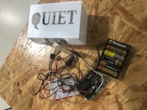
With my partner, I created a “Quiet Box” meant for a library, dormitory common room/kitchen, or any shared space where people are expected to not make too much noise. Our project is unique in two ways: firstly, because it measures sound over time, so if people speak or loud noises or made for a certain period of time, it alerts people to keep it down, and secondly, because it reacts to users in two ways (a beeping noise and a red light; meaning people who can’t see it will be able to heart it, and vice versa). The Quiet Box could be used by schools, shared living spaces, public libraries, or even in someone’s home to keep guests/kids quiet past a certain hour. This project could help keep shared spaces accommodating and peaceful for everyone there, and assure people stay respectful at public/private spaces.

Conception and Design

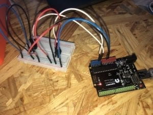
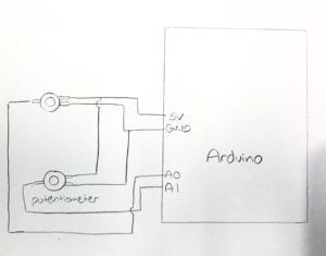
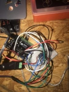
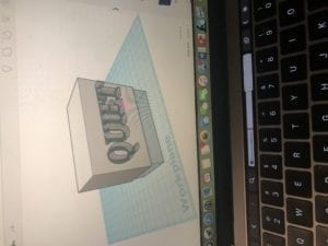
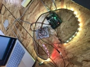
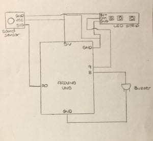
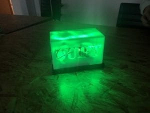
We knew our project was intended for quiet spaces, so we didn’t want to make the sound sensor trigger any reaction that was too disruptive, as the whole point of the Quiet Box is too keep people quiet and calm, and doing so would defeat the purpose of our project. We tested out different sound levels and LED brightnesses until we found ones we thought were just loud enough and just bright enough to grab people’s attention, but not so disruptive that they disturb other people within the space. We considered making the LED blink red, but realized this might be too disruptive in a quiet space, and decided on a constant, glowing red. To create our project, we used: RGB LED strips instead of lights, as we knew these would be able to change color and get bright enough to glow through our box a sound sensor, an on/off switch, and an external power source. Furthermore, we 3D printed a box, with thin, white walls so that it could appear to “glow” when the LEDs are on. We had considered using the laser cutter to create either a wood or clear plastic box, but wanted a semi-transparent look for the box that we knew the 3D printer would work best for.  I


Fabrication and Production

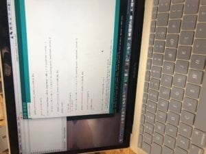
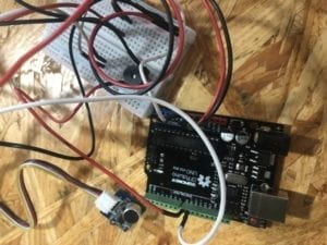
Our production process was lengthy, mainly because it took a lot of trial-and-error to perfect the code. We ran

into issues with the LED’s constantly blinking, even when little noise was being made, and so we had to build in a threshold within which the light only blinks if sound is over a certain level for a certain period of time. This way, one noise won’t trigger the light and sound reaction, but the build-up of sound will. We underestimated how see-through the walls of the 3D-printed box would be, and ended up making them so thin that you can just faintly see outlines of wires/LEDs through the box. Along with making the walls of the box a bit thicker, we should have added a piece of paper or see-through piece of plastic behind the ‘QUIET’ letters, so that you wouldn’t be able to see the wires so well from up close.

During user testing, we had 5 people suggest we find a way to hide the external-power battery pack (to make the project one single piece and look neater) and add an on/off switch on the outside (so that the box can be turned on or off without having to unplug the power source). We took this advice by putting the battery pack inside the box, and adding a toggle switch that can turn the device on and off.  \    

Conclusion

The goal of my project was to create a small, portable, sleek device which can be placed in any shared space (such as a public library or dorm) to keep noise levels of people down by notifying them when they are being two loud through a visual and audio cue. My project aligns with my definition of interact, because a trigger (talking too loud) on behalf of the user causes a response in the device (a red light and beep) which the user is able to directly see (and hear). My audience interacted with my project by making loud noises in order to trigger a light and sound response. If I had had more time, I would have reprinted the main box which all the wiring is in with slightly thicker walls. From the coding issues I ran into with this project, I learned that properly executing an idea is often much more complicated than expected, and that coding issues may just have to be solved with trial-and-error. Given that it was my first time 3D printing, I’m proud that I was able to design and print the box (even if it wasn’t perfect). I knew I wanted to make a project that I could execute neatly and play around with in terms of code and design, but have a clear idea of functionality with. Though wiring and coding the project proved to be more of a challenge than expected, I utilized the critical thinking and problem solving skills learned in class to ask for help, research online, and map out key aspects of my project. My project shows that even someone with limited knowledge of circuits, coding, and digital fabrication can create a device with function and purpose.

Drawing Machine – Lana Henrich, Week 4

Recitation Week 4

Circuit Building Process

Building this circuit was a bit of a challenge, as there were a lot more wires involved than in any of the previous ones I’ve built. I finished my first trial of building the circuit quite quickly, though the motor did not spin when I uploaded the code. I took apart the circuit and reconnected everything a second time, this time by using the negative and positive columns on the side of the breadboard (when before I had connected everything that needed power or ground straight to the Arduino). This made it easier to keep track of all my wires, as the cables weren’t all crossed over each other. When I then tried to plug in my circuit and upload the code, it worked perfectly. 

Building the Drawing Machine

I partnered up with Kyle to build the drawing machine out of our two motors. This part was relatively simple as connecting all the pieces was pretty straightforward. We ran into a bit of trouble with mapping the code, as we weren’t sure of where in the code to put our ‘map’ values. However, we looked up details about the map feature on the Arduino reference website and figured out where to put it. There was an issue with uploading my code onto my Arduino and the motor after we assembled the machine, but after just unplugging and re-plugging the power source we got it to work. The motors were a bit shaky, and therefore the lines the machine drew with the marker weren’t super smooth, but we were still able to create an ‘abstract’ artwork.


Question 1

I would be interested in building a machine that is able to track and record the movement of a pen/paintbrush, and can then recreate that art piece. The machine could be connected to a pen, which someone then uses like a drawing utensil.

I’ve enjoyed incorporating actuators into the circuits we build, because they allow for an extra level of interaction between the circuit and the user. In the circuit we built today, it allowed us to control the drawing machine by physically moving parts connected to the circuit, whereas in past circuits we used only the code to manipulate the circuit. With the idea I expressed earlier, the digital manipulation of art would be utilized because technology would be able to ‘recreate’ an artwork drawn by someone, with a code created that could alter parts of the drawing (e.g. stretching or compressing certain lines and changing drawing mediums). An actuator could be used to allow the machine movement while the artist is drawing their piece, and to allow for further manipulation of a copy of the art piece which the machine can create.

Question 2

I was very intrigued by Daniel Palacios Jimenez’s Waves art installation. I thought it was cool how the motion create by the ropes created an illusion of solid waves within the installation. Similarly, I liked how the motion sensors he selected allowed for interaction between viewers and the art piece. This is similar to the work I did during the recitation because, in accordance to the machine I built, viewers can also interact with it by turning the knob corresponding to the actuator. I think the selection of the actuator for Jimenez’s project was simple, because he wanted one that spun in order for the ropes to turn and create the visual illusion.