Smash That Like Button – Kevin Nader – Marcela Godoy

Context and Significance:

Smash That Like Button was a project, created by Alex Cleveland and me, intended to bring high striker (a classic staple of the carnival industry) into the modern era. The inspiration to build Smash That Like Button stemmed from (1) our shared love of carnivals, as well as (2) our research conducted during the group projects. The group projects pushed us to theorize what technology could look like one-hundred years from today; we took that prompt and, in a sense, “reverse engineered” it.  Instead of looking into the future, my partner and I decided to reach into the past; we aimed to take something timeless and pull it into the present day. It was from these reasons that the idea for Smash That Like Button was born. For those unaware, high striker is a carnival game in which the player is provided a large hammer intended for striking a target situated at the base of a large tower. The tower is outfitted with a small metal apparatus that shoots up when the target is struck. If the target is struck hard enough and the metal apparatus  reaches its highest intended point on the tower, it will ring a bell indicating that the player has won the game. 

In order to bring high striker into the modern era, we decided to implement a whole sleuth new electronic components aimed at enhancing the overall experience. Before I explain what these components consisted of, one must understand some key aspects of our project; (1) Our project took inputs from a pressure sensor located under a 3D printed model of a like button (hence the name Smash That Like Button), furthermore there are three thresholds the user may fall within depending on how much pressure they apply on the pressure sensor: low, medium, and high. Should the user’s input fall within the “low” threshold, they will be met with a red light accompanied by The Imperial March from Star Wars, moreover they will be given a thumbs-down.  Should the user’s input fall within the “medium” threshold, they will be met with a yellow light accompanied as well by The Imperial March from Star Wars, moreover they will be given a “meh” thumbs-up. Should the user’s input fall within the “high” threshold, they will be rewarded with a green light accompanied by the upbeat Cantina Theme from Star Wars, moreover they will be given a thumbs up. 

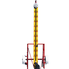
This is a photograph of a high striker

Conception and Design:

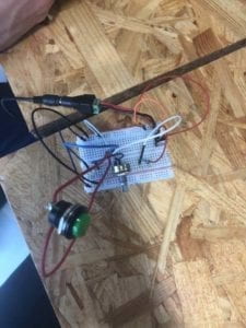
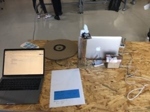
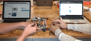
Here is a picture of Smash That Like Button during its user testing

Smash That Like Button is a reference to a popular trend on YouTube in which content creators request that their viewers like their video. YouTubers will typically say something along the lines of “don’t forget to hit that like button”, however the more zealous YouTubers will typically scream “REMEMBER TO SMASH THAT LIKE BUTTON”. This is important to note because, throughout our user testing, we originally had a bullseye as opposed to a like button, which generated confusion among the users as to what they were supposed to hit (some users understandably thought the “like button” intended to provide visual feedback had to be hit in some way). This issue was remedied by replacing the bullseye with a like button intended for smashing.

Another notable complaint we got during user testing was with regards to the pain experienced from smashing the thin and abused cardboard target, moreover users felt that the pressure sensor was not accurately reading there hits as sometimes a noticeably lighter hit would receive a higher rating . We 3D printed a new like button intended for smashing  with hopes that the plastic material would make it durable, moreover we added layers of styrofoam to the underside of the like button in order to serve as additional cushioning for we noticed that not only did it alleviate much of the pain that stemmed from smashing that like button, but it helped to give more consistent readings.

Finally we were told that our machine could look “cleaner”. We decided to enhance the overall appearance by laser-cutting a wooden casing that would serve to make Smash That Like Button both more presentable and portable.

All of the electronics required to make Smash That Like Button a reality would eventually be fit in this clean and compact casing.

Fabrication and Production:

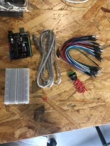
In this section, I will display the step by step process that lead to the creation of Smash That Like Button. Please bare in mind that the captions correspond to the photos above them.

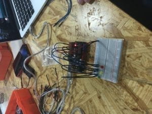
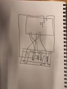
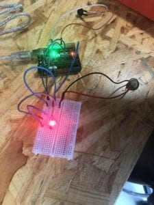
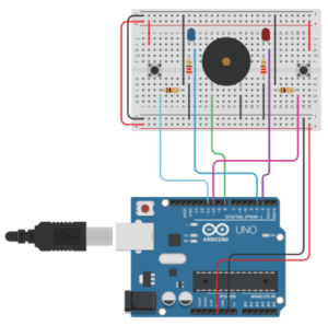
These are the 3 LEDs. Red corresponds to low, yellow corresponds to medium, and green corresponds to high. The lights were tested using blink.

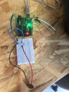
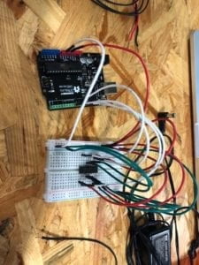
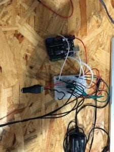
Here is when we attached the speaker. The installation process was simple for this component. We decided to use two breadboards for the sake of organization. The speaker was tested using tone melody.

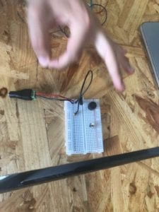
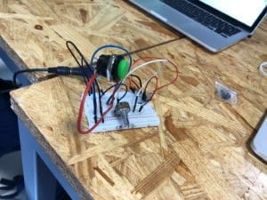
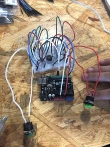
Here is a photo of our prototype. As you can see, we have added both a servo motor (for the thumbs up) and a pressure sensor (for taking inputs). You can also see our first attempt at casing the arduino and speaker. We utilized cardboard for the prototype casing.

Though not programmed yet, we attached the servo motor with our 3D printed thumb model to a stand. At the time of user testing, the servo motor was not programed; it was simply for show. 

138

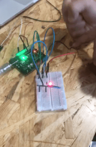
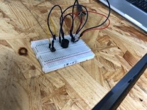
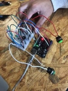
Here you can see a bit of our user testing in action. Though the user obtained the highest ranking, it is clear that the prior hit was equally as strong yet yielded a different response. Moreover, the prototype itself looks sloppy. 

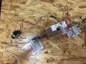
Here is the casing used to hold both the breadboards, the LEDs, the servo motor, and the speaker. We decided to put the speaker outside of the casing in order to amplify the sound. A large complaint during user testing was that the music was difficult to hear.

140

Here is a video of our casing with everything installed aside from the servo motor. As you can see there is a pillar for the servo to stand on that makes it more visible to the user. 

118

Here was our final test ensuring that the machine worked. As you may notice, the servo motor is different compared to recent photos. This is because we had to change the servo motor because the previous one was broken. This was very annoying to deal with because this issue took us a very long time to resolve. We kept doubting our code when in reality it was the hardware that was lacking. Opening the casing to reinstall the new motor also proved to be a challenge since there is not much space inside to work with. 

145

Here is a video of our final product in action! 

These are the notes for the songs that play depending on what threshold his obtained.

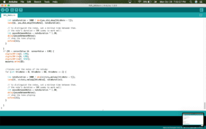
This is the code with which we defined the notes. In this regard, define means to specify the melody as well as duration of each note.

This was the coding that activated one of the 3 LEDs. It is here that you can clearly see our threshold concept. 

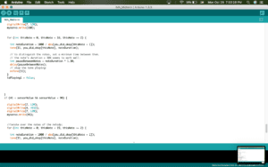
Tied into the coding for the LED’s is also the coding for the speaker. This code tells the speaker to play the appropriate song depending on the threshold obtained. 

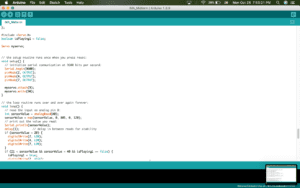
This last bit of code displays the servo motor coding. Thumbs up was defined as a turn to 180 degrees and thumbs down was defined as a turn to 0 degrees.

Conclusions:

In my opinion, the project achieved its goal. We aimed to pull high striker into the modern era through the implementation of additional outputs as well as a pop culture reference. The compact and portable size is a nice plus too. With regards to interaction, we wanted our project to be something that you could come back to and have a different experience every time. We felt a way to measure strength compounded with colorful outputs was an optimal way to achieve such a goal. During user testing, it was very fun to see people compare themselves to one-another in the spirit of friendly competition. The energy that would radiate from getting the green light was fun to both experience and spectate. If I could make the project more interactive, I would find a way to add in additional methods of inputting data. The concept Marcela brought up about a multiple person game was a very strong suggestion, but ultimately could not be implemented due to time constraints. We felt that if such a feature were to be implemented, it should be thought out thoroughly. We felt like our audience enjoyed the project. When a user got a red light, they were instantly determined to do better. Even if the user got the green light on the first try, their human nature urged them to see if they could do it again. I think, though very simple, our project did a good job at bringing out both the curiosity and determination we have within us. Something I learned from this project was to trust myself just a little bit more. My partner and I spent over two hours trying to fix the code of a servo motor that was entirely correct. It turns out that it was the motor itself that was broken. We ended up wasting so much times because we had too much confidence in the hardware, and not enough confidence in our own abilities. I think this project was a good reminder to believe in myself more. Though this was a relatively simple test of strength that lit up and played cool sounds, I think it was the little fire that in sparked in people that makes it worthy of discussion. Giving people a challenge to progress through, no matter the size, can help lead to personal growth. So, next time you watch a YouTube video, remember to smash that like button, 

Recitation 4: Drawing Machine

Introduction:

The overall goal of recitation 4 was to construct a drawing machine. The purpose of this recitation was to learn about both the h-bridge and the stepper motor; both of which are very useful components. Learning to implement these two components into future builds is on my mind thanks to this recitation.  Overall, I hope to be well versed with these two items because if they can be used to make something as complex and interesting as the drawing machine, then they can really help take our projects to the next level.

Construction:

This image here is the first stage of building. This build has a very complicated schematic, that compounded with the fact that I am very prone to making careless error inspired me to use what I’ve learned in previous recitations, and color coordinate my wiring.  The color coordination goes as follows: Power=Red, Ground=White, and PIN=Green. Thankfully, I would end up wiring this drawing machine without error. It did add an extra layer of comfort knowing that if I did make an error, it would be easy to spot the it. The parts present here are the h-bridge as well as a ton of wires.

This next stage is a rather quick one. All I did was attach the power adaptor to the breadboard. I included this as an entire step because I was worried that I would end up being one of the unfortunate souls who fried their arduino. I was very cautious to not let the 5 volts and 12 volts cross paths. 

This is a video of me finally attaching the stepper motor to the complete build. I uploaded the provided code, and what do you know? The stepper motor starting whizzing away. All that was left was to find someone else who finished and combine our motors together to make a drawing machine!

Here is the code for that simple motion of the stepper motor:

With a little bit of alterations to the code (as seen bellow) and some laser cut pieces, we successfully constructed the drawing machine. In my opinion, the most difficult part of this recitation was adding the potentiometer in the build. After doing so, the result was entertaining to say the least.

Question 1:

What kind of machines would you be interested in building?Add a reflection about the use of actuators, the digital manipulation of art, and the creative process to your blog post.

My favorite kinds of machines are the ones that test skill. I like the idea of improving skills, so machines similar to the speed game are very appealing to me. Moreover, this belief translated into my midterm project because that itself is also another kind of game. Instead of testing speed, mine tests strength.

For this class, I’d assume actuators refer to actual physical movers. I like actuators a lot because I feel that they add a much needed depth to both art and interactive machinery. While people expect art to stay stationary, I find that perhaps actuators can help breath new life into a tradition as old as time.

Digital manipulation of art is something that has peaked my interest due to an exhibit I saw last year. The exhibit featured paintings of regular images, however there was an external laser component that projected moving images over the paintings. These images proceeded to dance and move around the paintings as if they were in the world of the projected beings. I think such manipulation of art makes it far more entertaining to look at. 

When it comes to the creative process, I do not like describing it as a process. I think it is fair to assume that when we do something others may view as “creative” we do not always get to that result in the same method every time. I find the creative process to be more of an independent journey depending on the situation at hand. It is one that requires patience and the ability to leave no avenue unchecked. If done correctly, it can yield world changing results. 

Question 2:

Choose an art installation mentioned in the reading ART + Science NOW, Stephen Wilson (Kinetics chapter). Post your thoughts about it and make a comparison with the work you did during this recitation. How do you think that the artist selected those specific actuators for his project?

The London Fieldworks project was one that particularly peaked my interest. While the other projects give the viewer something interesting to watch, this project goes a different route (and I think the creators knew exactly what they were doing). The main actuators in this instance are both sound and vibrations. The main focus of this exhibit is to make the viewer look at what appears to be traditional art while being subject to experiences one typically does not see when looking at art, i.e shaking and surreal sounds. Such stimulation can drastically change the way someone views traditional art and I for one think that is an extremely interesting shift of the paradigm. While most artists try to change the art itself, the creativity displayed in the London Fieldworks gets you to look at the same art in a drastically different way. 

Recitation 2: Arduino Basics

Introduction:

For recitation 2, we were assigned to construct three circuits: a light that fades, a speaker that plays a nice little melody, and lastly a speed game. The purpose of this assignment was to enforce the basics of Arduino we learned in class that week. I hoped to be able to understand the basics of coding the arduino, for I feel like those skills are to be essential in the later projects of the class.

Building:

Circuit 1:

Circuit 1 was relatively simple to construct as shown in the schematic above. My lab partner and I had an easy time both coding and constructing this circuit.

Though simple, it was good preparation for what we would end up building later in the recitation

Circuit 2:

Circuit 2 was especially interesting to me because this was our introduction to sound, a key part of interactivity in my opinion. Once again, this was a relatively simple circuit to construct. 

Unfortunately, there was a small mishap, and a photo of this circuit was not taken. Instead enjoy this picture of my cat…

His name is Oreo and he really likes bread.

Circuit 3:

Unlike circuit 2, circuit 3 was documented in great detail (there is even a video). Up to this point, circuit three is the most complicated circuit we have built. I was very scared of wiring the entire thing and having it fail. Looking at a breadboard and trying to determine what is going wrong is extremely hard to me. This schematic is displaying a speed game. It is designed to register the amount of clicks imputed on both sides of the breadboard for ten seconds. It then takes that information and illuminates the light on the side that clicked a greater number of times in that ten seconds. Furthermore, it plays some pretty cool victory music. We tried to reprogram the music the be the game of thrones theme because why not? We utterly failed in this endeavor.

Here are some of the parts that would end up going into this circuit. Keep in mind, not everything is displayed in the image, but, as you can see, there are a lot of wires here.


Here is the first time we completed the building the circuit. Unfortunately we really messed up somewhere along this process which caused the circuit to not function. It ended up being a small issue with what a TA called “bridging the canyon”. Finding this issue was particularly annoying due to all the long wires protruding from the breadboard. 

This here is our completely finished circuit, and believe it or not, it is actually functioning!

I was particularly bad at this game…

Reflection: In the end I was very glad that we got that beast of a circuit up and running. I would have changed up the way I made that circuit if I had the chance. I believe color coordinating the wires as opposed to using whatever color I pulled out of the bad would have helped me greatly in completing this project. I now know how to organize my self for future recitations thanks to this. 

Question 1:

Reflect how you use technology in your daily life and on the circuits you just built. Use the text Physical Computing and your own observations to define interaction.

Technology dictates almost every single part of our lives. In reality, what is not considered technology? In my mind, anything that is not natural is technology. I even consider something as primitive as the wheel to be considered technology. From when you wake up in the morning to when you go to sleep, you are using technology. Everything from payments, all the way to the devices that heat our shower water runs on technology that most of us could not live without. In my opinion, some technology has more use than others. For example, the speed game we made has objectively less value compared to that of a x-ray machine. 

What is the definition of interaction? I see interaction as well as technology in a similar light. Similar to how technology’s usefulness falls on a spectrum, so does interaction. We interact quite a lot. With the objects surrounding us, other people, and yes… even technology. Interaction with even the most basic of things have infinite possibilities. Take a brick for example; you can do many different things. You could use it to build a house, you could use it as a hammer, a self defense tool, slap the word “supreme” on it and sell it for $40, etc.. Now look at technology. As mentioned in the reading, computers interact with a limited set of the human. Our eyes, fingers, and ears. This is a relatively small amount of interactivity compared to what had potential to be built. So based on both the reading as well as my opinions, interaction is simply a series of of inputs and outputs. Some things have more inputs/outputs than others, however everything in our life shares an interaction with us. 

Question 2:

Why did we use the 10K resistor with the push button?

The reasoning behind using a 10k resistor on a push button is to avoid a “floating pin” or in other words send ungrounded voltage to the arduino pins. 

Question 3:

If you have 100,000 LEDs of any brightness and color at your disposal, what would you make and where would you put it?

If I had 100,000 LED’s at my disposal I turn them into a costume. If I could have a light up outfit with 100,000 seperate lights, that would look absolutely insane. I could also have the lights light up in different ways to mix things up. I could probably become a DJ or something with an outfit like that. 

Schematic of Circuit 3:

Recitation 3: Sensors and our Terrible Security System

Introduction:

For recitation three, we were told to incorporate sensors into our projects. What were our projects? For the first time, we were allowed to build whatever we possibly could. For my project I wanted to make something with some sort of practical value, so my partner and I chose the vibration sensor. We wanted the vibration sensor to trigger a red light in addition to a speaker. In a sense it was a small security system. I really just hoped to learn how to apply my knowledge into a practical device and was really excited to try and do so. 

Security System:

When building the circuit, the hardest thing was decided what we actually wanted to build. Once deciding on a security system, we went ahead and got the necessary parts. By the grace of God, we actually managed to build this on our first try with no error. 

Here, you can see that we hooked up our sensor. We tested it with Analog Serial Read to make sure everything was in order.

After doing so, we added the LED to the security system. At first we wanted to stop here, but we knew we could do more.

Here you can see that we added a speaker. Furthermore, you can see my fist hitting the table and triggering the light. Though not possible to see through a picture, the speaker is functioning too.

This is the code for our security system: 

Reflection: Overall, it was a really fun process making this device. It was cool to see our knowledge manifest into an actual practical device. Being able to do such a thing only after three weeks gives me hope for what the future has in store. 

Question 1:

What did you intend to assemble in the recitation exercise? If your sensor/actuator combination were to be used for pragmatic purposes, who would use it, why would they use it, and how could it be used?

We intended to construct a security system through the use of a vibration sensor, an LED, and a speaker. We intended the vibration sensor to be under the floor and when someone were to step over it, it would notify someone through the flashing of a red light as well as an ugly sound. I think such a device has practical use. It is nowhere near as effective as an actual camera but it is a start. Anyone trying to defend themselves would surely appreciate it.

Question 2:

Code is often compared to following a recipe or tutorial.  Why do you think that is?

Let me preface this answer by saying I am an abysmal cook, so recipes are not my forte. I understand how coding can be related to one though. Similar to coding, recipes must be followed in the order they are presented to you. When coding, every line of code must be in the appropriate order or whatever you want to occur simply will not. No one puts their incomplete cake mix in the oven and cracks raw eggs onto whatever comes out. 

Question 3:

In Language of New Media, Manovich describes the influence of computers on new media. In what ways do you believe the computer influences our human behaviors?

Week One Recitation Documentation

Introduction

During week one recitation, we were introduced to circuits and the components that go into making them. We were provided schematics for three machines: a doorbell, a lamp, and a dimmable lamp.  Prior to this recitation, the only previous experience I had with circuitry was from my high school physics class. Though I had a very basic understanding on how to complete a circuit, this was the first time I would actually construct one. If I am being completely honest, I was a little overwhelmed by the sheer amount of components that lay before me. Furthermore, the schematics we were provided looked more like alien drawings than anything. The only thing I really wished to learn was how to read all of the jargon and what all the components I was attaching to a breadboard actually did. Learning how to solder was also pretty fun. There really was no inspiration for this project since it was simply assigned to us, however it did show me concepts with which I could apply to future projects.

Circuit 1

Here we have circuit 1, the doorbell. This was a relatively simple schematic to follow, however my lab partner and I both managed to screw this up many times. We would frequently connect wires to the wrong components. After help from a learning assistant, we were finally able to create our doorbell!

CIt was at this moment where we gave up reading the schematic and asked the learning assistant for help. After some much needed review on how to work a breadboard, we ended up with this…

Circuit 2

Circuit two was where things got really interesting. Midway through construction, we were called over to learn how to solder. We ended up using the arcade button pictured below as the switch for this circuit.

Before stating this circuit, my lab partner and I made the mistake of taking apart our entire circuit one, when in reality we could have utilized some of the existing wiring for circuit two. We were very angry after such a realization. There was one silver lining to this who situation. Upon asking a professor for help reconstructing our wiring, we learned that the capacitor can easily be implemented into the circuit by placing it right in front of the power supply as seen in the top left corner of the photograph. We ended up messing up once again and our circuit looked something like this… 

You may notice that the circuit at first glance looks normal, and you would be correct. Turns out we did build the circuit properly, we just had a dead bulb. This showed us that even though I am new to this electrical wiring, I should have some confidence in myself.

Circuit 3

Starting circuit three was much better than circuit two since we didn’t lead off with ripping out all of the existing infrastructure. This one was not that hard to build since it was simply a matter of adding a dimming feature to the LED lamp that was possible through inserting a variable resistor into the circuit. Despite the simple task at hand, you guessed it, we messed up.

This issue here was a miswiring between the LED and the other resistor. We had the wires flipped around. Upon fixing the wires, we created this bad boy, and let me tell you, having built all this for the first time felt so good! 

Reflection

Overall, the experience was a challenging yet rewarding one. Learning how to solder was great and it is a skill that I expect to frequently utilize throughout this semester. When it came to building the circuitry, it felt amazing to do this for the first time. Seeing those wires on the breadboard and being able to make sense of it all was a great feeling I’ll remember for a while. I look forward to expanding upon my skills and building bigger and better things.

Question 1

The circuits built in this recitation do display a level of interactivity. All circuits in this essay revolve around both input and output. Circuit one and circuit two utilize a simple switch for their input and use sound or light respectively as their output. Circuit three takes this one step further with the introduction of the variable resistor which takes the digital information of “on and off” and turns it into analog information by giving variation in the level of light emitting from the LED.

Question 2

Interaction design and Physical computing can be used to create interactive art in a plethora of ways. The main reason that comes to mind is the inclusion that interaction design brings to art. In my opinion, the quality of art is reflected in the impression it leaves on the beholder. If art contains a level of interaction with which the viewer is able to curate a unique experience, I feel like this makes the experience more memorable and thus validates the art as beautiful. Being able to have different expressions about what an art piece means because different people literally had different interactions with facilitates discussion and inspires others to push the bounds of how people can interact with what we originally thought to be stagnant.