Facebook Car Chase- Kathy Song- Rudi

CONCEPTION AND DESIGN:

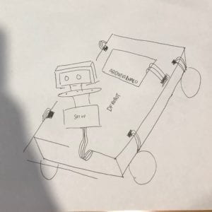
In our original idea, we planned to build a car that was going to run around the room and the user needed to chase it in order for them to break the habit of staying on social media. We understood that the car may encounter some obstacles along its path, so we included an ultrasonic sensor. This way, the car would turn every time it it bumped into a chair or table. The car itself was too wide for the sensor to detect obstacles in its blind spots. To accommodate for this, we built a stand on top of the servo motor so it would be able to better detect the obstacles. Since we have changed the goal of the project to pull the laptop away from the user, the we attached wheels to the bottom of the laptop to prevent any damages. We understand that in the real world, this would not be practical for daily use, however it is incorporated it as a part of our overall statement that people should use social media less.

Our materials included: D Robot kit, Arduino Romeo, Wires, Ultrasonic sensor, Servo motors, 3D printed stand. We used the DFRobot kit because it was more efficient than building a car from 3d printing amongst other materials. We used the Arduino Romeo because it had more ports so there was less of a need for a breadboard. The Ultrasonic sensor was used to detect objects , the Servo motor was used to rotate the sensor around to detect objects in its blind spots. We 3D printed a stand for the Ultrasonic sensor to attach it to the servo motor. It allowed the sensor to stay upright and be more stable. Lastly, we laser cut some wood to make the robot look more like a car (covering the wires). These materials were the best suited for our projects purpose because they were practical to use and would exist in a real life setting. Another option would be 3D printing the car and attaching bottle caps to the sides as wheels. The car could have had a cleaner look, however it would be inefficient and very time consuming.

FABRICATION AND PRODUCTION:

In terms of success, we successfully build a robot that had all its components working and running. The P5 code required a lot of work however it worked fine. The real challenge was implementing bluetooth into both the robot and P5. We could not find detailed instruction on how to make it work, and even though we found some documentation, we were unable to incorporate it after hours of coding it. During user testing session, the robot stopped working and we were unable to get valuable feedback because the users were not able to truly experience our project. However, we did incorporate wheels to the bottom of the laptop to make the pull easier. This was an effective suggestion but not practical. We did not have to make too many decisions regarding its design. We followed the very basic design that came with the robot kit. The only modifications we made were to incorporate other important machine parts like the servo and sensor.

CONCLUSIONS:

The original goal of our project was to get users to get off of facebook and run around the room to chase the car. It would give them some exercise and remind them to get off of social media. However, the new goal of the project was to make a statement to the user, that there would be a physical pulling of your computer if they spent too much time on facebook. This project aligns with our definition of interaction because we believe that interaction is the series of movements by at least two actors, both responding to one another. Although the user is interacting with facebook, it is not a good type of interaction. However, the robots response to this “bad” form of interaction reminds the user to interact with the world around them. If we had more time, my partner and I would definitely incorporate the bluetooth function to make the original project work. From the setbacks we faced, my partner and I learned how to better improvise for our project to see what was the best fit for our situation. There was no way we would have made the robot work with the bluetooth function with the amount of time and resources that we had. This project really tested our patience but at the same time, we both learned so much about out ability to time manage and use new functions within our project.

In terms of the purpose of the project, it mattered a lot to the both of us because we wanted to be creative while making a statement. People should care about this project because it serves a message to the current generation and generations to come. I challenged myself because I was able to code everything from the beginning to end, and did not model it after code online.

Recitation 10: Media Controller

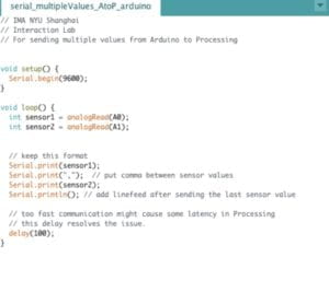
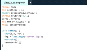
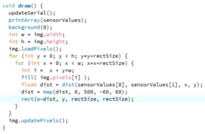
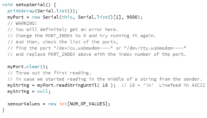
In today’s recitation, I used two potentiometers to create a controller to change the way my image moved. Depending on the value of my potentiometers, the image would swirl around in all different directions. This part was significant to my project because I used “The Scream” by Edvard Munch. Since the original painting had a lot of texture in regards to swirls, I wanted to enhance its shape and direction. In the beginning, I was not sure how I was going to make this happen. While it was doable, it was hard to manipulate the code so that the end result would shift. I uploaded my code from Arduino to processing. Changing the code in Arduino was easy, however, the code in Processing was a lot more intricate. The code for the recitation project worked by breaking the image into pixels and then shifting the pixels from left to right, from up to down.

After reading Computer Vision for Artists and Designers, I feel that my understanding of movement in technology has been enhanced. I was enlightened by how certain angles could change the entire narrative of the pictures, and create different mirages. Ever since learning about computer science and taking Interaction Lab, I have realized the importance of the calculation, timing, angles, and the very logistical side of coding. In today’s recitation project, breaking the image into pixels and then shifting the pixels at a certain time created an illusion that the photo was moving. Likewise, in our final project, the timing of the processing code would trigger a response in the Arduino which also provides a very logistical point of view.

Video

Arduino Code

Processing Code

Documentation 9: Final Project Process

Jonathan’s project was called Labyrinth. The project was based on a mythological story in which two users would be running around a maze. The first player would be trying to run through the maze while the second player would be chasing the first player. This would all be animated on Processing while the controls would be on Arduino. My feedback for this project was that the concept sounded similar to Pac-man and it would be easier for him to create this project based off of similar code. Others were worried that the game would not provide enough backstory. I thought that this idea was interesting because he is taking something from folk stories and his imagination, and turning it into an artistic game using processing and Arduino. I found this to be super creative and different from the other ideas that are meant to bring some sort of efficiency into our lives. This project is creating a more meaningful experience because modern society is moving at a rapid pace with technological development, there is not much to ground the people nowadays. This project is a hybrid of technology and storytelling, which can give the user a meaningful experience interacting with this kind of technology.

Bing’s project was an Interactive Heart Rate Monitor. Her plan was to build a monitor that would measure a person’s heart rate when they were exposed to certain stimuli. They would use an infrared sensor that would be doing the reading. This information would be sent from Arduino into Processing. Our group members thought that this idea was unique because they have been exposed to the stimuli, the webcam would take a photo of them during their most fearful moment. It seems like it would be a fun way to interact with technology because the user has no control over the situation. The response to the technology is completely based on the body’s reaction. Our feedback was that the design should force the user to only look at the screen (block out all external stimuli) so there might be a more reactive response. This project would create a meaningful experience with the user because they would be baited with a scary video and their experience would be recorded. It was a sequence of movements that would demonstrate a different type of interaction compared to Jonathan’s project.

Julie’s project was about making a tapping game similar to Guitar Hero. There would be a song playing in the background and the user had to push the buttons that sounded similar to the tones in the music. This project was interesting because it sounded like a fun concept, and less complicated than guitar hero. As a group, we were worried about how practical this game would be because she plans on only using three buttons in total for the tones. Even in the simplest songs, three buttons would not be enough. We also suggested her to make this game so that it would be multiplayer instead of one person playing. I thought this project was interesting because the interaction was not with a screen but with buttons, which provides this sense of old-time nostalgia that we lack from our constant interaction with screens.

I did not discover a new Definition of interaction, but discussing with my group members allowed me to filter out certain ideas for future projects. It also opens my mind up because their definition of interaction includes ideas that solely have to do with entertainment. I always put the pressure on myself to create something useful and entertaining, but now I am enlightened by games that incorporate different aspects of technology.

The feedback that I received was to talk to Nick because he also created a car, his insight would be helpful because I can model my car after something similar, with the same purpose of running around the table. According to my group members, the most successful part of my proposal was the idea behind it, they liked the idea that this piece of technology would keep the person active and allow them to move around while decreasing screen time usage. The least successful part of my proposal was that they thought that it was impossible to send the information from processing to the car while it is moving around the table. I disagree with this feedback and I do not believe that it will impact my project. Throughout my research, I have gathered that I can use the Bluetooth HC-06 module to send the information from processing to my car. Other feedback tackled the issue of the design and code which I did not find too helpful.

Final Project Essay

Vroom! Too- Much- Screen- Time!  

Project Statement of Purpose

The modern world is becoming more and more addicted to social media. In 2018 alone, American adults spend up to 11 hours per day “interacting” with media. Our project aims to find an entertaining way to reduce people’s screen time on their computers with an interactive toy car. When the user hits a certain screen time, their computer screen will begin flashing with a timed Gif of 2 minutes. The car will sense this and run around the table. The user’s job is to stop using their computer and chase the dog around the table until the Gif is finished running. My inspiration came from the Clocky the alarm clock that runs away for you to wake up. Since the alarm clock forces the user to physically interact with the alarm clock, I wanted to create a car that would roll around the table for the user to chase while waiting for the Gif to finish running. Clocky the Alarm clock has a sturdy center with wheels on the side. I plan on designing something similar but would look more like a car. The goal of this project is for the user to take breaks during their screen time and receive light exercise from chasing the car around.

Project Plan

Our project aims to reduce the user’s screen time. Every hour, an interactive Gif would pop up for a few minutes. It is impossible to close this gif from the computer screen. At the same time, a small car would start rolling around the table, the goal of the user would be to chase the car around to make sure it does not fall off the table. By the end of the set time, the Gif would expire and the car would stop running. This way the user would be able to return to their work after a small break. I plan on 3D printing the car and attaching the Arduino within the car, this way, it is invisible to the eye. There would be servos attached to the car to make the wheels start turning. I plan on adding flashing LED lights to the front of the car, where the headlights belong and a speaker that would project constant noise while it is running. We plan on animating Gifs through processing, but I am unsure of the exact details of how to incorporate a timed Gif function. We will design the car so that it would look like a decorative desk toy. The animated Gif should be funny and entertaining. I understand that the user may be frustrated if we interrupted them in the middle of something important, so I will try to make it as funny as possible. My partner and I plan on reaching a milestone every week. She will be focusing on the code for processing and the animation of the Gif, and I will be focusing on the toy car’s design and code. By next week, I would like to have most if not all of the code for the Arduino complete. The week after that I would like to have the car equipped with all its functions and be able to move. After this is complete, we would like to be able to link the two together and complete this project a few days before its deadline to make any more modifications to the final design.

Context and Significance

I was inspired by Clocky the alarm clock because I thought the idea was such a good example of an interaction between a machine and a person. I wanted to incorporate this into other aspects in a person’s daily life other than helping them wake up. More importantly, I wanted to tackle a problem that has been plaguing our society for years to come. The project will help raise awareness of the severity of screen usage and hopefully can promote users to take this issue more seriously. To prepare for this project,  I have researched several car projects on the Arduino website to find a suitable design. I have found several designs that I will manipulate to create one that is suitable for this project. The most realistic design is the Obstacle Avoiding Car. This would be useful since the car would be running around the desk, it should be careful enough not to destroy any valuables. This project aligns with my definition of interaction because I believe that interaction is the series of movements by at least two actors, both responding to one another. This machine will force the user to interact with it for a greater purpose. This project is unique, however, it originates from Clocky the alarm clock. The problem that Clocky aimed to resolve is human laziness and inability to wake up. Though it is a serious issue, Clock is entertaining and empathizes with the user. Our car aims to contribute to human dependence on technology and incorporates a fun way for them to spend time away from their screens. Our product is intended for students and office workers who have an open space to work with. It is of special value to the targeted audience because their working environment is stressful and it is easy to spend hours on end attached to the computer screen. If successful, I doubt that this project will become something that people will buy, but it could be given as a free gift to people who attend hackathon events or important gatherings. Subsequent projects may include other interactive projects that tackle other issues in society today with an entertaining value.

Documentation 8: Serial Communication

Both exercises required the cooperation between the Arduino and Processing. When we first started the collaboration exercises between processing and Arduino, I could not understand how the two worked together. After going through the code I started to better understand how it worked. Once the sample code is changed and uploaded to the Arduino, you would then run the code from processing with the information from the same ports.

Exercise 1:

Materials: Two Potentiometers, Breadboard, Arduino, Wires

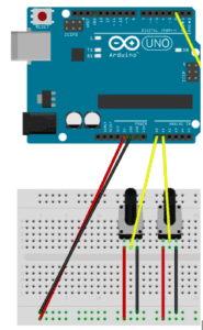
I attached the two potentiometers to the breadboard and Arduino. After running the code, I was able to check the two potentiometers by reading the serial monitor. Since I was only using two sensors, I got rid of the third one. I wanted to delete the line() but I realized that doing that would cause other problems because the code must read everything above the line function in order for the code to run. The upload was successful and I was able to create an ellipse that changed in height and width. I then used that to my advantage and created a small ellipse that I used as my draw tool for my etch machine. Attached below is the code and the video.
Arduino Code

//Arduino Code for Etch Machine

void setup()

{

 Serial.begin(9600);

}

void loop ()

{

 int sensor1 = analogRead(A0);

 int sensor2= analogRead(A1);

 Serial.print(sensor1);

 Serial.print(“,”);

 Serial.pring(sensor2);

 Serial.println();

 delay(100);


}

Processing Code

// IMA NYU Shanghai

// Interaction Lab

// For receiving multiple values from Arduino to Processing

/*

* Based on the readStringUntil() example by Tom Igoe

* https://processing.org/reference/libraries/serial/Serial_readStringUntil_.html

*/

import processing.serial.*;

String myString = null;

Serial myPort;

int NUM_OF_VALUES = 2;   /** YOU MUST CHANGE THIS ACCORDING TO YOUR PROJECT **/

int[] sensorValues;      /** this array stores values from Arduino **/

void setup() {

 size(500, 500);

 background(0);

 setupSerial();

}

void draw() {

 updateSerial();

 printArray(sensorValues);

 // use the values like this!

 // sensorValues[0]

 float xVal= map(sensorValues[0], 0, 1023, 0, width);

 float yVal= map (sensorValues[1], 0, 1023,0, height);

 ellipse (xVal,sensorValues[1], 10,10);


 //

}

void setupSerial() {

 printArray(Serial.list());

 myPort = new Serial(this, Serial.list()[ 2 ], 9600);

 // WARNING!

 // You will definitely get an error here.

 // Change the PORT_INDEX to 0 and try running it again.

 // And then, check the list of the ports,

 // find the port “/dev/cu.usbmodem—-” or “/dev/tty.usbmodem—-”

 // and replace PORT_INDEX above with the index number of the port.

 myPort.clear();

 // Throw out the first reading,

 // in case we started reading in the middle of a string from the sender.

 myString = myPort.readStringUntil( 10 );  // 10 = ‘\n’ Linefeed in ASCII

 myString = null;

 sensorValues = new int[NUM_OF_VALUES];

}

void updateSerial() {

 while (myPort.available() > 0) {

   myString = myPort.readStringUntil( 10 ); // 10 = ‘\n’  Linefeed in ASCII

   if (myString != null) {

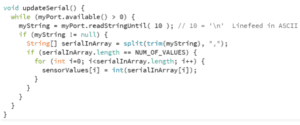
     String[] serialInArray = split(trim(myString), “,”);

     if (serialInArray.length == NUM_OF_VALUES) {

       for (int i=0; i<serialInArray.length; i++) {

         sensorValues[i] = int(serialInArray[i]);

       }

     }

   }

 }

}


Exercise 2:

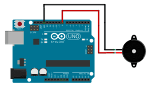
In the second exercise, I had attached the speaker to the breadboard and Arduino through a wire. The code was a bit more confusing for me to understand so I went online to see if I could find a file of code that might work better. Ultimately I stuck with the sample code. For this exercise, I changed the port on the processing to [1] to match with the Arduino. I was also able to play around with the tones and pitch of the sound that was emitted from the speakers. I found this one particularly exciting because i was able to move my finger across the keypad to create sounds, a different example of interaction.
Arduino Code:

#define NUM_OF_VALUES 1    /** YOU MUST CHANGE THIS ACCORDING TO YOUR PROJECT **/

/** DO NOT REMOVE THESE **/

int tempValue = 0;

int valueIndex = 0;

/* This is the array of values storing the data from Processing. */

int values[NUM_OF_VALUES];

void setup() {

 Serial.begin(9600);

 pinMode(7, OUTPUT);

}

void loop() {

 getSerialData();

 // add your code here

 // use elements in the values array

 // values[0]

 // values[1]

 //  if (values[0] == ‘H’) {

 //    digitalWrite(13, HIGH);

 //  } else {

 //    digitalWrite(13, LOW);

 //  }

 tone(7, values[0]);

}

//recieve serial data from Processing

void getSerialData() {

 if (Serial.available()) {

   char c = Serial.read();

   //switch – case checks the value of the variable in the switch function

   //in this case, the char c, then runs one of the cases that fit the value of the variable

   //for more information, visit the reference page: https://www.arduino.cc/en/Reference/SwitchCase

   switch (c) {

     //if the char c from Processing is a number between 0 and 9

     case ‘0’…’9′:

       //save the value of char c to tempValue

       //but simultaneously rearrange the existing values saved in tempValue

       //for the digits received through char c to remain coherent

       //if this does not make sense and would like to know more, send an email to me!

       tempValue = tempValue * 10 + c – ‘0’;

       break;

     //if the char c from Processing is a comma

     //indicating that the following values of char c is for the next element in the values array

     case ‘, ’:

       values[valueIndex] = tempValue;

       //reset tempValue value

       tempValue = 0;

       //increment valuesIndex by 1

       valueIndex++;

       break;

     //if the char c from Processing is character ‘n’

     //which signals that it is the end of data

     case ‘n’:

       //save the tempValue

       //this will b the last element in the values array

       values[valueIndex] = tempValue;

       //reset tempValue and valueIndex values

       //to clear out the values array for the next round of readings from Processing

       tempValue = 0;

       valueIndex = 0;

       break;

     //if the char c from Processing is character ‘e’

     //it is signalling for the Arduino to send Processing the elements saved in the values array

     //this case is triggered and processed by the echoSerialData function in the Processing sketch

     case ‘e’: // to echo

       for (int i = 0; i < NUM_OF_VALUES; i++) {

         Serial.print(values[i]);

         if (i < NUM_OF_VALUES – 1) {

           Serial.print(‘, ’);

         }

         else {

           Serial.println();

         }

       }

       break;

   }

 }

Processing Code:

 import processing.serial.*;

 int NUM_OF_VALUES = 1;  /** YOU MUST CHANGE THIS ACCORDING TO YOUR PROJECT **/

 Serial myPort;

 String myString;

 int PORT_INDEX = 1;

 // This is the array of values you might want to send to Arduino.

 int values[] = new int[NUM_OF_VALUES];

 void setup() {

   size(500, 500);

   background(0);

   printArray(Serial.list());

   myPort = new Serial(this, Serial.list()[ PORT_INDEX ], 9600);

   // check the list of the ports,

   // find the port “/dev/cu.usbmodem—-” or “/dev/tty.usbmodem—-”

   // and replace PORT_INDEX above with the index of the port

   myPort.clear();

   // Throw out the first reading,

   // in case we started reading in the middle of a string from the sender.

   myString = myPort.readStringUntil( 10 );  // 10 = ‘\n’ Linefeed in ASCII

   myString = null;

 }

 void draw() {

   background(0);

   // changes the values

   // for (int i=0; i<values.length; i++) {

   // values[i] = i;  /** Feel free to change this!! **/

   // }

   values[0] = mouseX;

   map(values[0], 220, 2000, 0, 100);

   // if (mousePressed) {

   // values[0] = ‘H’;

   // } else {

   // values[0] = ‘L’;

   // }

   // sends the values to Arduino.

   sendSerialData();

   // This causess the communication to become slow and unstable.

   // You might want to comment this out when everything is ready.

   // The parameter 200 is the frequency of echoing.

   // The higher this number, the slower the program will be

   // but the higher this number, the more stable it will be.

   echoSerialData(200);

 }

 void sendSerialData() {

   String data = “”;

   for (int i = 0; i < values.length; i++) {

     data += values[i];

     //if i is less than the index number of the last element in the values array

     if (i < values.length – 1) {

       data += “, ”; // add splitter character “,” between each values element

     }

     //if it is the last element in the values array

     else {

       data += “n”; // add the end of data character “n”

     }

   }

   //write to Arduino

   myPort.write(data);

 }

 void echoSerialData(int frequency) {

   //write character ‘e’ at the given frequency

   //to request Arduino to send back the values array

   if (frameCount % frequency == 0) myPort.write(‘e’);

   String incomingBytes = “”;

   while (myPort.available() > 0) {

     //add on all the characters received from the Arduino to the incomingBytes string

     incomingBytes += char(myPort.read());

   }

   //print what Arduino sent back to Processing

   print( incomingBytes );

 }
Processing Code

// IMA NYU Shanghai

// Interaction Lab

/**

* This example is to send multiple values from Processing to Arduino.

* You can find the arduino example file in the same folder which works with this Processing file.

* Please note that the echoSerialData function asks Arduino to send the data saved in the values array

* to check if it is receiving the correct bytes.

**/

import processing.serial.*;

int NUM_OF_VALUES = 10;  /** YOU MUST CHANGE THIS ACCORDING TO YOUR PROJECT **/

Serial myPort;

String myString;

// This is the array of values you might want to send to Arduino.

int values[] = new int[NUM_OF_VALUES];

void setup() {

 size(500, 500);

 background(0);

 printArray(Serial.list());

 myPort = new Serial(this, Serial.list()[ 1 ], 9600);

 // check the list of the ports,

 // find the port “/dev/cu.usbmodem—-” or “/dev/tty.usbmodem—-”

 // and replace PORT_INDEX above with the index of the port

 myPort.clear();

 // Throw out the first reading,

 // in case we started reading in the middle of a string from the sender.

 myString = myPort.readStringUntil( 10 );  // 10 = ‘\n’ Linefeed in ASCII

 myString = null;

}

void draw() {

 background(0);

 // changes the values

 values[0] = mouseX;

 values[1] = mouseY;

 // sends the values to Arduino.

 sendSerialData();

 // This causess the communication to become slow and unstable.

 // You might want to comment this out when everything is ready.

 // The parameter 200 is the frequency of echoing.

 // The higher this number, the slower the program will be

 // but the higher this number, the more stable it will be.

 echoSerialData(200);

}

void sendSerialData() {

 String data = “”;

 for (int i=0; i<values.length; i++) {

   data += values[i];

   //if i is less than the index number of the last element in the values array

   if (i < values.length-1) {

     data += “,”; // add splitter character “,” between each values element

   }

   //if it is the last element in the values array

   else {

     data += “n”; // add the end of data character “n”

   }

 }

 //write to Arduino

 myPort.write(data);

}

void echoSerialData(int frequency) {

 //write character ‘e’ at the given frequency

 //to request Arduino to send back the values array

 if (frameCount % frequency == 0) myPort.write(‘e’);

 String incomingBytes = “”;

 while (myPort.available() > 0) {

   //add on all the characters received from the Arduino to the incomingBytes string

   incomingBytes += char(myPort.read());

 }

 //print what Arduino sent back to Processing

 print( incomingBytes );

}