Recitation 006: Blog post of the group project for Interaction lab by Kenan(Arthur)

     In my perspective, “interaction” is defined as a complicated and creative procedure of “input-process-output” between two actors. Within this definition, there are two components that should be emphasized. The first is that this “input-process-output” procedure is conducted by two actors. As mentioned in the essay “The Art of Interactive Design”, interaction is “a cyclic process in which two actors alternately listen, think, and speak” (Crawford 5). “Listen” here stands for input, “Think” represents process and “Speak” is regarded as output. Besides this procedure within single entity, the term “two actors” is also essential since interaction requires two actors to communicate with each other, serving as the other’s source of input and receiver of output. The second component is “complicated and creative”. The process of interaction is supposed to contain some sort of complexity and creativity. According to the essay, the observation like “People jump out as they hear the sound of branches crashing to earth” should not be considered as interaction but merely reaction (Crawford 5). In this scenarios, although the “input-process-output” procedure technically exists , it can not be seen as interaction since the “reaction” is too natural without complexity and creativity.

    After I generated my initial definition of “interaction” from the assigned readings, I went on looking up for some projects that can help me better understand my own definition. The most interesting one I found on the “Creative Applications Network” website is a project called “Weather Thingy”. Basically it is a “sounds controller that uses real time climate-related events to control and modify the settings of musical instruments”. More specifically, it can automatically make changes to the music pieces that you are playing regarding the current climate it recognizes. If it’s windy, then your music will be played in a loop between left and right channels in either your speakers or headphones. If it’s rainy, your music will sound like you’re under the water. I think this project well aligned to my definition of interaction. There is “input-process-output” procedure between players and this project. For the project, it receives information of the climate and the music pieces, then it identifies what kind of climate it is and how it should integrates the climate information and music pieces together with creativity and intelligence, lastly it outputs the final work. For the player, he/she listens to the pieces produced by the project and thinks about if the pieces match with his/her expectations, then he/she can choose to change certain parameters to make the pieces sound better. As we can see, the interaction happens here contains some sort of complexity and is overall unexpected. The project uses its own logic and intellectuality to produce pieces with special characteristics.

    The second project I examined that are less aligned to my definition is the one called “Scribb”, which is a “Pen-Paper-Mouse interface”. In this project, the mouse functions as a scanner that can transform the drawings in the paper into the equivalent digital visual information that can be presented on the screens. Here the interaction process is overall complete and explicit. For the mouse, it scans the drawings, creates a equivalent digital 2D model as processing and presents the drawing on the screens as output. For the drawer, he/she sees the drawing on the screen, then decides if the drawing satisfies his/her goals and then makes responding changes. However, the problem laid underneath is that this kind of interaction is too primary and natural without enough creativity and complexity. When we think of scanning, we naturally expect the mouse to scan the drawing we created and present it on the screen. During this process, the mouse doesn’t contribute to the improvement of the drawing with its own intelligence and autonomy, instead it just functions as a coping machine.

    The product our group created is an intellectual glove that can translate sign languages into voices for people with speaking difficulties. The glove tracks the movement of the users’ hands with a huge amount of sensors. Then it relates the movements with specific sign languages in its storage and translates those sign languages into standard writing paragraphs in a reorganized order with its own intelligence and capability for machine learning. Lastly, it outputs in a smooth voice to help the users better communicate with other people. The users can hear the outputting voice and change its tunes ot word choice preferences based on its personal demand. We think the interaction of our products is really complete, creative and complicated since it overcome the “language barriers” for the minority group in the society and can only be achieved with a lot of sensors and high techniques like machine learning.

Poster:

Work Cited

Crawford, Chris. “What Exactly is Interactivity.” The Art of Interactive Design, pp. 1-6.
Recitation 006: Documentation 3 for Interaction lab by Kenan(Arthur) Gu

 Circuit:

1. components:  1) a Breadboard: a basic stage for building the circuit 

                                  2) a LED: if the circuit works, it can light

                                  3) a 220 ohm Resistor: control the voltage so that the voltage for the LED will not be too much in order to protect it.

                                  4) a Moisture Sensor: to identify and examine the humidity of the current environment and make it quantitate and visible on digital devices like Laptop.

                                  5) an Arduino: a computer that can send and receive information to achieve the goal of interactive command.

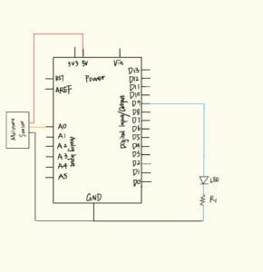
2. Diagram:

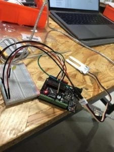
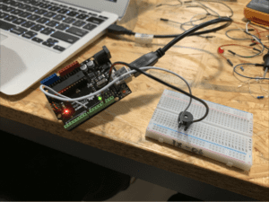
3. The picture and video of the completed circuit:

4. The description of this circuit: 

  We built this circuit to test the humidity of items or the environment. We connect the moisture sensor to the analog in A0 and connect the resistor and LED to the Pin 9. With the code we made, when the humidity the sensor identified exceed 100, the LED will be lighten to show that it is too humid. 

Question:

  1. I intended to assemble an LED with a Moisture Sensor in the recitation session. I think the potential pragmatic use of my combination is to monitor the humidity for plants. Once the humidity is too high or too low that are unsuitable for plants, the LED will light to remind the users of emergency. This design will help users better take care of their plants.
  2. I hold neutral position over the claim that “Code is often compared to following a recipe or tutorial.” This reveals that code is consists of various logically fluent steps and we need to strictly follow the instructions for building one code just like recipe or tutorial. However, code is not just about following the steps, it requires much more creativity than recipe or tutorial.
  3. First of all, since we human rely on computer too much today to help us to complete a lot of tasks, we will be deeply influenced by its language–digital coding, our way of thinking will contain more logic and clear but we may lose the capability to feel the world in an emotional way. Also computer makes us see a broader world than we have actually experienced in person, thus we may act and think more comprehensive than before.


Recitation 006: Documentation 2 for Interaction lab by Kenan(Arthur) Gu

Circuit 1: Fade

  1. Components:  1) an Arduino Uno : a physical computer to drive and make command to the whole circuit

                              2) a Breadboard: a basic stage for building the circuit

                              3) a 220 ohm resistors: to limit the volt distributed on the LED to ensure it will not broke

                              5) a LED : can be lighten and make the command of the Arduino Uno observable

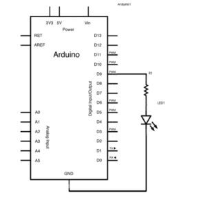
2. Diagram: 

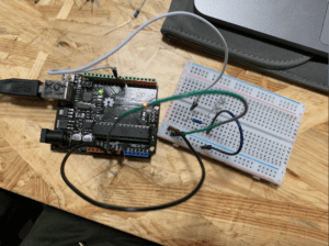
3. Pictures and video of the completed circuit:

4. The process of building the circuit: We first connect the 5V and ground on the Arduino to the breadboard, then we connect the resistor and the LED to the pin 9. The circuit worked good with the drive of the coding, as you can see that the LED was blinking in the video before.

Circuit 2: toneMelody               

  1. Components:  1) an Arduino Uno : a physical computer to drive and make command to the whole circuit

                              2) a Breadboard: a basic stage for building the circuit

                              3) a buzzer: make sound to testify the circuit and make the code observable

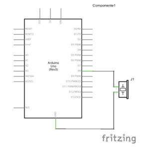
2. Diagram:

3.  Pictures and video of the completed circuit:

4. The process of building the circuit: The connection for this circuit is quite simple, we just connected the positive of the buzzer to the pin 8 ,and its negative to the ground. The circuit worked well as you can see in the video.

Circuit 3: Speed Game

  1. Components:  1) an Arduino Uno : a physical computer to drive and make command to the whole circuit

                              2) a Breadboard: a basic stage for building the circuit

                              3) two LEDs: to make the result of the match observable

                              4) a speaker: make signal sound as time ends

                              5) two pushbuttons: a major input in this circuit for the two participants in this game. The game is tested by weighing which participant click the button faster.

                              6) two 220ohm resistors: limit the volt on the LED for protection

                              7) two 10ohm resistors: limit the volt on the pushbuttons

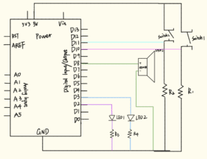
2. Diagram:

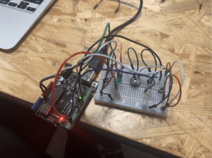
3. Pictures and video of the completed circuit:

4. The process of building the circuit: This is quite complicated circuit. We built it with the help of the online resources. While strictly follow the guidance, the circuit still couldn’t work. We checked the circuit once again and found out that a wire between the LED 1 and the R3 was broken. So we changed this wire to another and the circuit worked well as you can see in the video. What a tensive game! 

Answer to the Questions:

  1. In my daily life I enjoy the convenience of the technology. I interact with the devices which contain a lot of technology mostly by using them, inputing what I want (tap, swipe. etc) and receiving information from them. I rely on the coding written by those engineers. When I was building the circuit, however, I change my perspective as a consumer of the technology to an experiencer and creator of technology.  For me, interaction means the mutual communication between two entities.
  2. I’ll make a device that the LED inside can light in different way adapting to the music. I am gonna put it in somewhere of the campus so that we can have a place for partying !!(Just kidding, I’m not a fan of parties lol)

Interaction Lab: Exercise 1 Documentation — Kenan Gu

Circuit 1: Door Bell

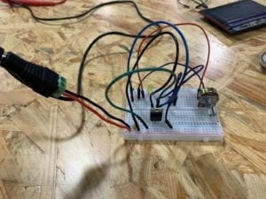
  1. Components:  1) a 12 volt power supply: provide power for the whole circuit

                              2) a LM7805 Voltage Regulator: a transformer that expands the number of             components a single power can connect

                              3) a 100 nF Capacitor: to stabilize and smooth the flow of electricity in this circuit

                              4) a Speaker: make noise to see if the circuit is connected correctly

                              5) a Push-Button Switch: determine the connecting status of this circuit, creating interactivity

                              6) a Breadboard: a basic stage for building the circuit

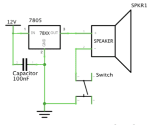
2. Diagram:

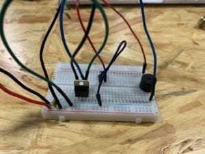
3. Pictures and video of the completed circuit:

4. The process of building: We insert the Voltage Regulator first between the positive and negative of the Breadboard. Then we put the Push-Button Switch into this breadboard with its different wires in two different rows. Then we connect the Speaker with one side to the switch and other side to the negative. The circuit worked perfectly as you can see in the video.

Circuit 2: Lamp

  1. Components: 1) a 12 volt power supply: provide power for the whole circuit

                            2) a LM7805 Voltage Regulator: a transformer that expands the number of             components a single power can connect

                            3) a 100 nF Capacitor: to stabilize and smooth the flow of electricity in this circuit

                            4) a LED: if connects with power, it can light

                            5) a 220 ohm Resistor: control the voltage so that the voltage for the LED will not be too much 

                            6) a Push-Button Switch: determine the connecting status of this circuit, creating interactivity

                            7) a Breadboard: a basic stage for building the circuit

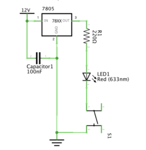
2. Diagram:

3. Picture and video of the completed circuit

IMG_2249

4. The process of building: Based on the foundation of the previous circuit of the speaker, it become slightly easier for us to build this circuit. We just change the speaker to the LED and insert a 220 ohm Resistor between the Voltage Regulator and the LED. We didn’t encounter any issues along the way, which is quite fortunate.

Circuit 3: Dimmable Lamp

  1. Components: 1) a 12 volt power supply: provide power for the whole circuit

                            2) a LM7805 Voltage Regulator: a transformer that expands the number of             components a single power can connect

                            3) a 100 nF Capacitor: to stabilize and smooth the flow of electricity in this circuit

                            4) a LED: if connects with power, it can light

                            5) a 220 ohm Resistor: control the voltage so that the voltage for the LED will not be too much 

                            6) a Push-Button Switch: determine the connecting status of this circuit, creating interactivity

                            7) a Breadboard: a basic stage for building the circuit

                            8) a 10K ohm Variable Resistor: to make the lamp dimmable

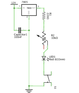
2. Diagram

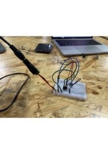
3. Picture and video of the completed circuit:

4. The process of building: Built on the foundation of the previous circuit 2, we just insert the variable resistor between the 220 ohm resistor and the LED. However, the circuit didn’t work first time we tried and the LED can’t be lighted. We then figured out the connection of the circuit was wrong since we connected the positive of the LED to the negative of the 220 ohm Resistor, and the variable resistor’s positive and negative were connected, making the circuit an open circuit. Then we corrected it and the circuit worked good as shown in the video.

Circuit 4: Switch the switches

1. Components: 1) a 12 volt power supply: provide power for the whole circuit

                            2) a LM7805 Voltage Regulator: a transformer that expands the number of             components a single power can connect

                            3) a 100 nF Capacitor: to stabilize and smooth the flow of electricity in this circuit

                            4) a LED: if connects with power, it can light

                            5) a 220 ohm Resistor: control the voltage so that the voltage for the LED will not be too much 

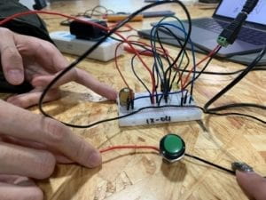
                            6) a soldered arcade button: determine the connecting status of this circuit, creating interactivity

                            7) a Breadboard: a basic stage for building the circuit

                            8) a 10K ohm Variable Resistor: to make the lamp dimmable

2. Diagram

3. Picture and video of the completed circuit:

4. The process of building: Based on the foundation of the third circuit, we just switched the push-button switch to the soldered arcade switch. Circuits worked great as shown in the video.

Questions:

1. From my perspective, the switch in the circuit is the core part of interactivity. Interactivity is defined as “a cyclic process in which two actors alternately listen, think and speak”. The definition shows that interactivity emphasizing on conversations between two entities. In the circuit that we build, the two entities should be people and the reacting item (either the speaker or the lamp). Human like us give out commend by clicking the switch, and the switch turns the open circuit to a closed circuit. Then the speaker start sounding and the lamp start lighting, delivering information we can perceive. Thus, the two entities have conversations and the key part of this conversation to exist is the switch.

2. Just as Zack Lieberman shown in the video. The interaction design and physical computing can      be used in many ways. The interactive painting Lieberman designed that allowed people to play with the whatever drawn in the screen suggests that interaction design can be used to stimulate inspiration in the artistic field. I also see the potential from this case that we can create lots of innovative and funny computer games for enriching our options for entertainment. The second case Lieberman showed in the video is the “Eye Tracker” to help those disabled artists to paint with their eyes. This innovation is really inspiring and significant since it brings up the idea of social responsibility. Trough interaction design and physical computing, we can make complex operations accessible to the disabled, leading to a brighter future for them.