Recitation 8: Serial Communication by Kyle Brueggemann

Overview

For this recitation, I worked on combining the functions of Arduino and Processing to create two different projects. First, an etch-a-sketch that draws a line based on the outputs of two potentiometers. Also, a buzzer whose sound turns on with the press of the keyboard as well as changing pitch and duration based on the x and y coordinates of the mouse’s position.

Exercise 1: Etch A Sketch
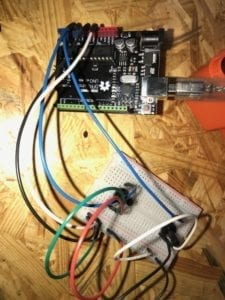
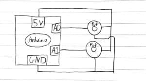
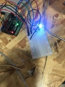
For the etch-a-sketch, I worked on successfully transmitting the values from two potentiometers from the Arduino to Processing and then using those values to draw a line based on the position of variables x & y. Once having easily connected the two potentiometers, the next step is to go to the Arduino code to correctly read the values coming from the potentiometers, and serial print them in a format that Processing can interpret. Then, I had to map the sensor values into a number ratio that applies to the size of my Processing sketch. Then I created a line whose first two points are a variable equal to the two sensor’s previous values, and whose second two points are equal to the two sensor’s current values. This allows a smooth, and consistent line to be controlled by the potentiometers. I ran into a few problems as I did not correctly insert the commas between the different array values in Arduino, which led to them not being sent correctly to Processing. I also first tried to draw my line with repeating ellipses, however, in order to make a smooth etch-a-sketch, I learned to use the line function and use the previous values and current values in conjunction. This etch-a-sketch involves a lot of interactivity because it allows the user to communicate with two sensors and create a visual work of art to their desire. This is interaction because it involves the user first inputting values through the potentiometers, and then the laptop to output a series of lines in accordance with those values. Then, having visualized what’s on the screen, the user can then continue to draw their desired artwork. This is a cyclical process of communication and understanding.

Code

Arduino

void setup() {
Serial.begin(9600);
}

void loop() {
int sensor1 = analogRead(A0);
int sensor2 = analogRead(A1);

Serial.print(sensor1);
Serial.print(“,”); // put comma between sensor values
Serial.print(sensor2);
Serial.println();

delay(100);
}

Processing

import processing.serial.*;

String myString = null;
Serial myPort;

int NUM_OF_VALUES = 2;
int[] sensorValues;
int v;
int b;

void setup() {
size(600, 600);
background(0);
setupSerial();

}

void draw() {
updateSerial();
printArray(sensorValues);

stroke(255);
line(sensorValues[0],sensorValues[1],v,b);
println(sensorValues[0]);
println(sensorValues[1]);
v = sensorValues[0];
b = sensorValues[1];

}

void setupSerial() {
printArray(Serial.list());
myPort = new Serial(this, Serial.list()[ 3 ], 9600);

myPort.clear();
myString = myPort.readStringUntil( 10 );
myString = null;

sensorValues = new int[NUM_OF_VALUES];
}

void updateSerial() {
while (myPort.available() > 0) {
myString = myPort.readStringUntil( 10 ); // 10 = ‘\n’ Linefeed in ASCII
if (myString != null) {
String[] serialInArray = split(trim(myString), “,”);
if (serialInArray.length == NUM_OF_VALUES) {
for (int i=0; i<serialInArray.length; i++) {
sensorValues[i] = int(serialInArray[i]);
}

sensorValues[0] = int(map(sensorValues[0], 0, 1023, 600, 0));
sensorValues[1] = int(map(sensorValues[1], 0, 1023, 0, 600));

}
}
}
}

Exercise 2: Musical Instrument
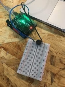
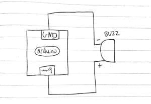
At first, I was entirely confused by this exercise as I had no direction with my coding. Just a lot of already-written lines of code but nowhere to dive in. However, thanks to the fabulous fellow Jingyi, a once arbitrary chunk of code somehow now made sense, and I was able to incorporate the lines I needed in order to make the buzzer function. While there were similarities in the coding process in relation to the etch-a-sketch, there were also entirely new elements due to this exercise being from Processing to Arduino. The first step is to establish that the array transmitted to Arduino is made of 3 separate values. One value for the mouse’s x-coordinate, one for the mouse’s y-coordinate, and one for the key pressed function. Once establishing values from these functions into the array, I was able to move onto coding the Arduino. On the Arduino, I created an if, else statement. If the corresponding value of the keyboard being pressed is sent, then the buzzer will have a tone, and if the keyboard isn’t pressed, then it will have no tone. Then inside of the if statement for the buzzer having a tone, I set the frequency and duration of the tone in relation to the values I set for the x and y coordinates of the mouse. One important thing for this code is I had to use the map function in order to create a variable for the frequency that had an applicable range of values. This exercise is definitely interactive as it encourages the user to use the mouse and keyboard to get different tones from the buzzer, and then having heard the tones, they will be inspired to play with the inputs even more to create a melody.

Code

Processing

import processing.serial.*;

int NUM_OF_VALUES = 3;

Serial myPort;
String myString;

int values[] = new int[NUM_OF_VALUES];

void setup() {
size(500, 500);
background(0);

printArray(Serial.list());
myPort = new Serial(this, Serial.list()[ 1 ], 9600);

myPort.clear();
myString = myPort.readStringUntil( 10 );
myString = null;
}

void draw() {
values[0] =mouseX;
values[1] =mouseY;

if (mousePressed) {
stroke(random(255), random(255), random(255));
//strokeWeight(10);
line(pmouseX, pmouseY, mouseX, mouseY);
}

if (keyPressed) {
values[2] = 1;
} else {
values[2] = 0;
}

printArray(values);

sendSerialData();

echoSerialData(200);
}

void sendSerialData() {
String data = “”;
for (int i=0; i<values.length; i++) {
data += values[i];

if (i < values.length-1) {
data += “,”;
}

else {
data += “n”;
}
}
myPort.write(data);
}

void echoSerialData(int frequency) {
if (frameCount % frequency == 0) myPort.write(‘e’);

String incomingBytes = “”;
while (myPort.available() > 0) {
incomingBytes += char(myPort.read());
}
print( incomingBytes );
}

Arduino

#define NUM_OF_VALUES 3

int tempValue = 0;
int valueIndex = 0;
int freq;

int values[NUM_OF_VALUES];

void setup() {
Serial.begin(9600);
pinMode(9, OUTPUT);
}

void loop() {
getSerialData();

req = map(values[0], 0, 500, 31, 4978);

if (values[2] == 1) {

tone(9, freq, values[1]);

} else {
noTone(9);

}

}

void getSerialData() {
if (Serial.available()) {
char c = Serial.read();

switch (c) {

case ‘0’…’9′:
tempValue = tempValue * 10 + c – ‘0’;
break;

case ‘,’:
values[valueIndex] = tempValue;
tempValue = 0;
valueIndex++;
break;

case ‘n’:

values[valueIndex] = tempValue;
tempValue = 0;
valueIndex = 0;
break;

case ‘e’:
for (int i = 0; i < NUM_OF_VALUES; i++) {
Serial.print(values[i]);
if (i < NUM_OF_VALUES – 1) {
Serial.print(‘,’);
}
else {
Serial.println();
}
}
break;
}
}
}
Preparatory Research and Analysis by Kyle Brueggemann

A

Initial definition: Interaction is defined as a cyclical process where one actor performs one task, and another reacts, which then in response the original actor responds again.

Definition post-midterm project: Throughout the previous developments in this class, I have learned that interaction is the process of communication and response between two participants, that continuously goes back and forth.

Evolution: My definition of interaction has not changed significantly, but I believe there is an importance that every interaction is composed of at least two characters. And in order for the interaction to be present, there must be a cyclical process of communication and response. However, at the beginning I was not sure how intuitive this process needed to be, however, now I am more confident that this is rather a cycle and not simply a process of deliverance and feedback. One player gives an input, which is feedback, and then this cycle should be able to be repeated over and over. Something that simply reacts to a singular stimulus is not total interaction.

B

In line with my definition:

On Space Time Foam, Tomas Saraceno

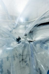
A project that I found that resonates with my idea of interaction is On Space Time Foam by Tomas Saraceno. This interactive art installation invites visitors to walk on top of a transparent membrane and float in the air. This installation is entirely interactive because it entices the visitors to literally become apart of the installation and have fun with it. They will not only interact with the membrane by crawling over it and altering its shape, but they will also interact with others also climbing across the installation, as their weight will fluctuate the position of the membrane, then causing the position of others on the installation to change. This will then influence individuals to interact with each other by moving across a shared medium. Not only is there communication through the movement of the individual and the installation, but there is also the response of the movement of the membrane and the individual. This is supposed to represent the interconnectedness of the rhythm of time and space. Not only can one interact with the installation directly, but those who wish to not take the daring task of climbing on top of the clear cloud can view the installation from below, giving an entirely unique perspective. This follows my definition of interaction because it allows multiple beings and mediums to send information through their movement, in which others can then be triggered by, and respond to with their own movements. This mimics the rhythm of being and communicating with the physical.

Obliteration Room, Yayoi Kusama

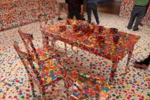
Another art installation that I believe follows my definition of interaction is Yayoi Kusama’s Obliteration Room. This installation is an all-white furnished room in which each visitor is given a colored sticker to place somewhere. They are then given the freedom to place the colored sticker anywhere in the room. Over time, the once all-white room will turn into an architectural rainbow. Following my definition, this is entirely interactive as each visitor is inclined to permanently change the appearance of the exhibition. Then as more and more people add color to the room, new visitors will be influenced to place their colored stickers over less colorful parts of the room. As the room’s appearance is always changing as long as new guests enter the exhibit, it will give off an entirely new reality in which the guests that come thereafter will be influenced by the past, but will also design a new physical future.

Not in line with my definition:

Passage, Doh Ho Suh

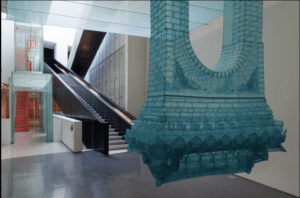
An example of a project that does not utilize interaction is Passage by Do Ho Suh. This work is a series of sculptures made of translucent fabric that formulate a message on the impermanence of historical meaning. While this art installation is extremely meaningful, it does not evoke any sort of interaction following my definition. There is the process of appreciation and awe that comes from a visitor who is able to empathize with this piece, however, there is nothing the user can do that causes the installation to react in return. This is a one-way street of communication, not a two-way street. In fact, any kind of physical interaction with the installation is extremely discouraged as it is made from a delicate fabric.

C

Interaction is a two-way street of communication and response between at least two beings/objects that stimulates new perceptions and realities.

Recitation 7: Processing Animation by Kyle Brueggemann

Recitation Exercise:

For the initial exercise, I wanted to take an entirely new design in order to create an animation that displays rotating flowers. For the first step, I created the design of the flower. The flower design included the coding for the center of the circle as well as the coding for the petals, which coded a singular flower and copied it 5 times, around the designated radial rotation. I then took this flower and copied it across the entire page by establishing it under myFunction. By allowing this, I took the x and y coordinates of the flower and used a for() function in order to duplicate the flower across the entire background. Then, once having an entire page filled with flowers, I used a rotation function in order to rotate the radians of the flower in relation to the position of the mouse as well as the passing of the frames, in order to incorporate a degree of interactivity. The final result is a screen full of flowers that rotate by themselves, and can either speed up or slow down rotation with the user’s interaction. For the future, I would like to create randomly generated flowers that change color and speed and float down from the top of the screen that can be controlled by the user’s mouse. This would bring in a new level of complexity but it is something I would genuinely like to tackle next. For now, this exercise has taught me how to use myFunction to duplicate the same shape multiple times and apply the same animation to all of them simultaneously. I also learned the importance of the push + pop matrix when dealing with void draw functions.

Code:

void setup() {
size(600, 600);
background(255);
smooth();
noStroke();

}
void draw() {
background(255);
for(int i = 0; i<width+100; i=i+120){
for(int j = 0; j<height+100; j=j+120){
fill(0);
//ellipse(i, j, 50,50);
myFunction(i, j);
}
}
}

void myFunction(float x, float y) {
pushMatrix();
translate(x, y);
rotate(radians(frameCount + mouseX));
//petals
fill(190, 120, 150);
for (int i = 0; i < 5; i++) {
ellipse(0, -40, 50, 50);
rotate(radians(72));
}
//circle
fill(230, 180, 150);
ellipse(0, 0, 50, 50);
popMatrix();
}

Recitation Homework:

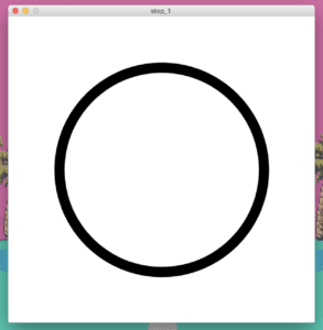
step 1: this first step proved to be very simple. just to draw a circle and place it in the center of the canvas

step 2: for this next step, I created an integer for the diameter of the circle. and then under the draw function, I established a formula that allows the integer to increase and then decrease in order to expand and contract the circle

step 3: in order to make the circle change color continuously, I added the HSB color mode function, I then created a variable for the stroke called c, which allows the color to change to whatever that variable is. Then I took the variable c and created a formula under the draw function which allows it to increase and decrease to change to all colors of the rainbow

step 4: this was the most difficult step. I replaced my fixed x and y values for the position of the circle and replacd them with the integers x and y. I also added integers called xmove and ymove, Then I created a keypressed function in which for each arrow key, it would apply a value to the xmove and ymove integer. Then in the main code, I added two formulas which add the xmove and ymove values to the original x and y values. This is so every time the keys are pressed, these values of xmove and ymove, indicated by the arrow keys would add to the x and y values of the circle and create a new position.

Code:

void setup(){
size(600, 600);
strokeWeight(20);
}

int z;
int steps = 3;

int c;
int step = 3/2;

int x = 300;
int y = 300;
int xmove;
int ymove;

void draw(){
x=x+xmove;
y=y+ymove;

pushMatrix();
background(100);
circle(x,y,z);
colorMode(HSB, 100);
stroke (c, 100, 100);

c = c+step;
if (c>100 || c<0) {
step = -step;

}

z = z+steps;
if (z>400 || z<-400){
steps = -steps;

}

popMatrix();

}

void keyPressed() {

if (key == CODED) {
if (keyCode == RIGHT) {
xmove = 2;
} else if (keyCode == LEFT) {
xmove = -2;
} else if (keyCode == UP) {
ymove = -2;
} else if (keyCode == DOWN) {
ymove = 2;

}}}

Reflection:

During this function I learned a lot about the interaction between setup, draw, and myFunction. The most interesting code I learned was the keypressed, which allowed the pressing of the keyboard to initiate the input of a value to a certain variable. Although I am still slightly confused by the colorMode variable, as it allows me to change the values that line up with the color spectrum, and I know how to code it, however I’m still unsure about how its placement within setup and draw affects its functioning. Overall, I’m glad I was able to do this exercise because it genuinely helped me further my understanding of Processing.

Recitation 6: Processing Basics by Kyle Brueggemann

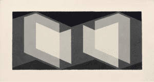
Josef Albers – Biconjugate

I chose this artwork to create my motif from because it uses a lot of geometric proportions and layering. I enjoyed the overall aesthetic and thought it would be a good challenge to develop my processing skills, but also not something entirely unreachable. This image stood out to me because the monotone color scheme and different layers gave it a clean, yet interesting overall appearance. 

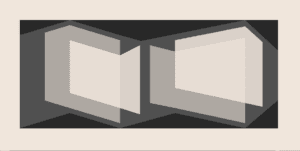
In my coding in processing, I wanted to make close to an exact replica of this image as Possible. While it didn’t turn out absolutely perfect, I believe my final product turned out pretty good. In order to achieve this motif, I started with the back layer of color, and slowly added more and more layers on top of each other. This facilitated the process for this design, especially because the geometric angles are typically parallel with the previous layers’ angles. The process involved a lot of math as well as a lot of experimentation with values to determine how to keep the proportions exact between all the elements.

The final product is very similar to the original inspiration. There are a few angles that don’t lineup exactly, but every single element still retains its role in the development of the overall aesthetic. I do believe that Processing was a good means for realizing this design as it provided a very suitable workspace for creating such a geometric design. Using coding to draw allowed me to calculate the precision needed for such designs that involve precise proportions.

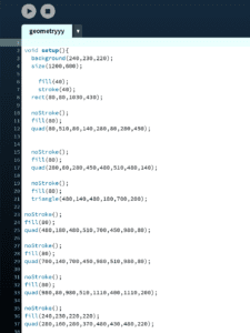
Code:

void setup(){
background(240,230,220);
size(1200,600);

fill(40);
stroke(40);
rect(80,80,1030,430);

noStroke();
fill(80);
quad(80,510,80,140,280,80,280,450);

noStroke();
fill(80);
quad(280,80,280,450,480,510,480,140);

noStroke();
fill(80);
triangle(480,140,480,180,700,200);

noStroke();
fill(80);
quad(480,180,480,510,700,450,980,80);

noStroke();
fill(80);
quad(700,140,700,450,980,510,980,80);

noStroke();
fill(80);
quad(980,80,980,510,1110,400,1110,200);

noStroke();
fill(240,230,220,220);
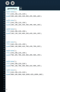
quad(280,160,280,370,480,430,480,220);

noStroke();
fill(240,230,220,220);
quad(480,220,480,430,560,455,560,180);

noStroke();
fill(240,230,220,150);
quad(280,100,280,430,480,490,480,160);

noStroke();
fill(240,230,220,150);
quad(180,130,180,400,280,430,280,100);

noStroke();
fill(240,230,220,150);
quad(600,180,600,410,700,430,700,205);

noStroke();
fill(240,230,220,150);
quad(700,205,700,430,980,490,980,150);

noStroke();
fill(240,230,220,220);
quad(700,160,700,350,980,410,980,105);

noStroke();
fill(240,230,220,220);
quad(980,105,980,410,1050,425,1050,168);

}

Mood Mind Match – Kyle Brueggemann – Marcela Godoy

CONTEXT AND SIGNIFICANCE

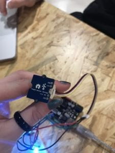
My first experience working with groups in this class was with the skit presentation where we had the idea of a beanie that could record dreams. I was slightly inspired by this idea with the development of a device that could somehow record our emotions and reveal something about our internal world through technological outputs. Throughout the previous developments in this class, I have learned that interaction is the process of communication and response between two participants, that continuously goes back and forth. My partner, Eva, and I wanted to use this definition of interaction along with the idea of expressing emotions to develop a project inspired by the premise of mood rings. We wanted to use the idea that the temperature of your skin is linked to your current mood and by using the Arduino to measure that temperature, and to then output it as a comprehensive value, we could allow a level of interactivity that promoted the interactor to interact with the Arduino and then gain a deeper level of comprehension from the Arduino’s direct output. We further developed upon the mood ring idea by creating a relationship compatibility tester, in which two different people allow their temperature to be read, and these values are then inputted into RGB LEDs, and then from the color of the LEDs, they can determine their compatibility based on how similar the colors are. We decided that by including two users in the interactivity process, there is the encouragement of interactivity not only between human and machine but also human and human. This project is intended for anyone who is interested in the psychology behind body temperature as well as anyone who seeks the entertainment factor of finding their possible compatibility with another person.

CONCEPTION AND DESIGN


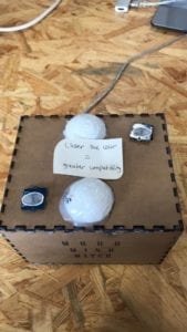
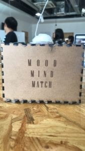
Our project was a laser cut box containing all of the electrical components. There is one hole in the side of the box that allows for the USB cord to go to the laptop. There is also a laser etched title on the front of the box with our project name, “Mood Mind Match”. On the top cover of the box, we included two holes on opposite sides for the temperature sensors. On top of each sensor is a picture of a fingerprint. We also included three holes in the center: two for each LED, and one for our 3d printed heart reset button. On top of each LED, and covered in hot glue in order to give a unique appearance, are two ping pong balls cut in half. In the designing of all of these elements, we wanted to place the temperature sensors on opposite ends of the box in order to encourage the participants to face each other during the process of finding out their compatibility. This not only facilitates communication during the very exciting process of finding out compatibility, but it also assists in the placement of our LEDs We decided to place the LEDs parallel to each temperature sensor in order that each person could determine which LED lined up with each sensor. Most of our design elements were placed not only to make the use of this project as easy to understand as possible but also to follow a simple, clean, aesthetic that attracts people to our project. The placement of the half ping pong ball on top of each LED is the most apparent example of this strive towards a clean aesthetic. We could have chosen to leave the LEDs out in the open, but the design choice of covering them up conceals more of the mechanical components and allows for a more cohesive appearance of our project. We had a couple of original ideas in the design of our box that included slightly different placements of the temperature sensors and LEDs, but we decided the best placement was having the sensors face each other, with the LEDs parallel and in the middle of the box.

FABRICATION AND PRODUCTION


It was directly after the User Testing Session that we decided to start with the 3d fabrication process. We had already designed our laser cut box, but it was a team decision to leave the actual fabrication process until after user testing so we don’t waste any materials remaking our project in case we had run into any major problems during the testing session. One change after user testing is we decided to include instructional text on our box that alerts the user that the closer the color of the LEDs, the greater the compatibility. It was during the testing session that we realized there was no direct information about the meaning of the color of the LEDs unless told to the users, however we wanted our project to be able to function without explanation so this text gave the users the information they needed in order to understand the context of the LED’s output. After testing, another alteration that we wanted to add to the design was the addition of a picture of a fingerprint on top of each sensor. We also added this for a similar reason of having more obvious directions for how to interact with the project. With these pictures placed on top of the sensor, there is no question as to what the participants should do. I believe both of these adaptations were highly effective because they facilitated the audience’s comprehension of the project’s meaning as well as the functionality of its interactive components.

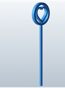
In order to incorporate the fabrication processes in our project, we decided to laser cut a box in order to contain all of the electrical components. We ran into an issue here, however. We decided to wait until the day before the project was due to laser cut this box and right before we attempted to cut it, the machine stopped working. Although the laser cutter soon was functioning again, this entire experience made both my partner and I extremely nervous and definitely taught us a lesson about procrastination. Especially working with technology, which has the ability to break down, or be finicky, it is always helpful to be ahead of schedule in order to avoid situations such as this. We had another issue in the fabrication process in our project. We had wanted to 3d print a heart on a stick. The heart would sit atop the box while the stick would go through a hole and connect to a reset button for our circuit. However, even after scheduling a 3d printing appointment, the heart just would not print correctly. Still not sure about why this didn’t work as it was tried multiple times, but from my own perspective, I have definitely learned, when working with fabrication processes, to do them all very early on as these machines are not as reliable than I had thought. The fact that the heart would not print meant that we could no longer use the reset button and we had to manually reset the project every time a user wanted to interact with it, which was not ideal, but we had to make do with the resources we had.

CONCLUSIONS

To recap, the goal of this project was to create an electrical circuit with the Arduino that encourages interaction following my own personal interpretation of what interaction truly is. Another goal of the project was to use some form of digital modeling in order to design the circuit. I believe that our project really aligned with a lot of aspects of my personal definition of interaction. It involves multiple lines of communication and the transferring of information between both of the compatibility test participants. It also involves the transfer of information through the temperature sensor, and then the transfer of values from the temperature sensor to the LEDs. The color of the LEDs then encourages a reaction to the participants as well as between the participants based on their level of compatibility. This entire process encourages the audience to feel inclined to put their fingers on the temperature sensor, and then react excitedly when they receive the news of their compatibility. In reality, all of the audience figured out how to interact with the project, however, the reactions varied intensely. Some were extremely excited with the project, and some didn’t react very much when the LEDs turned on. I’m not sure if this is just their personality, or if there are ways to invite more interactivity. However, even though I believe there is a healthy level of interactivity, I believe that we could have incorporated a few more components, given fewer time constraints, such as a buzzer that would beep if the temperature values were close enough. This would allow a fine line to be drawn on what level of compatibility is present between the testers in order to release any confusion about the meanings of the LEDs’ color. I was also thinking we could use the same buzzer, and have it play a certain tune based on the degree of compatibility. Such as three beeps for lovers, two beeps for friends, and one beep for strangers. I believe the incorporation of both a visual and audio output would invite even more of an emotional response from our audience so if revisited in the future, I would love to incorporate such. Going back to the setbacks involved in the laser cutting and 3d printing process. I am a bit disappointed we couldn’t 3d print the heart reset button, however, I’m also glad that my partner and I were able to experience the challenge of technical difficulties in order to encourage us to approach such technologically heavy processes with greater leniency. From our various issues with technology, I definitely feel more prepared for dealing with these machines in the future. From our accomplishments, I definitely have greater confidence in my ability to code and work through different programs. I also feel much more comfortable in a group project setting, as my partner and I worked together very well. In all, I’m glad that our project turned out the way it is. We were able to take a simple idea and execute it neatly in order to construct an effortless symbol of interaction. There are always improvements that could be made with more time, but for all of our effort in coding, modeling, and circuit building, I am content with the result.