Boxes know the answer-Jiahui Zhang(Nina)-Marcela

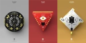
What should people do when they face an unclear future with hesitation? This was the initial inspiration when I heard the group project’s topic. After reading external reading materials and articles, also going through those creative websites, I formed my definition of interaction, which is a procedure of two or more objects affecting each other in various ways in a short period of time. If we split that procedure into closer details in a simple way, it is like what Igoe and O’Sullivan define in Introduction to Physical Computing—interaction is “listening, thinking, and speaking” in human terms from Chris Crawford’s perspective and “input, processing, and output” in computer terms (XX). However, an interactive device must be able to change its output as long as the audience changes its alterable input, while the algorithm is fixed. This definition is enhanced by our group project of the 2119 interactive device and the two projects—Blackberry Winter and BIY™—I found on the Creative Application. When I researched on the interactive devices, I found BIY™(Believe it Yourself), created by Shanghai-based design studio Automato.farm, which are three different kinds of real-fictional belief-based computing kits. The kits will respond to the user based on traditional Chinese Geomancy and Fengshui, which is based on rules of positions of mountains and rivers nearby and tell the fortune. Will we be more confident if we know some hints of the future? Will we be more willing to deal with obstacles if we have some advice? The book of answers is a book to give suggestions to hesitating questions. By placing your hand on the top of the book, ask the question in your heart, and open the book, you can find some instructions from the book. However, the users actually know that the book is based on nothing. This then becomes less interactive and convincing. So we decided to make a device, using sound sensors to analyze the audio and open a box with an answer on it, which seems more convincing and scientific. By this method, the user may have some new inspiration and unexpected reflection on their questions.

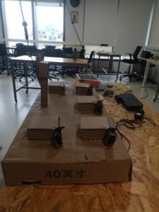
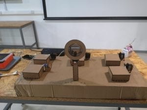
To make this idea become reality, we first draw the drafts of the device. We want to let the audience ask the question aloud, as well as the answer can automatically show up in front of them. So we designed a microphone-look sound sensor to get the audio data with a button that controls the start and the end of receiving the audio information. Meanwhile, the sensor is connected to a few boxes, which can be opened by servo from inside, with the answer on the inner side of the cover. However, Leon wants to use the meme from the Sponge Bob. Thus we changed the shape of the microphone into a conch shell, which refers to the repeated question in the Sponge Bob: “why not ask the magic conch?” The conch shell is 3D printed in a pure white color, and we use the wood board to laser cut those boxes. However, we found it was hard to open the box from inside by servo. And it also fails by using the stepper to rotate a rope, which linking to the box cover to open the box. We then change to use LED light to suggest which box the user should open after asking the question.
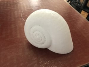
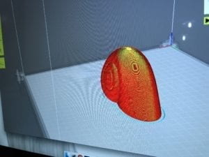
But during the user testing session, we found that most people would treat the conch as a speaker instead of a microphone. Meanwhile, we needed to open the box for them since many of the users didn’t know how to treat those boxes even if the light was on. The instruction given by the LED was not clear enough to let the audience understand what to do, as well as the shape of the conch was kind of misleading. So we finally changed the conch back into the shape of an old microphone and put servos on the side of the boxes to open the covers.
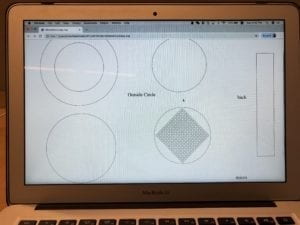
Elements and materials we eventually use:
(1) Breadboard *1
(2) Arduino UNO *1
(3) Servo 180 *5
(4) M/F, F/F wires *n
(5) Laser-cut boxes *5
(6) Laser-cut Microphone *1
(7) Huge base cardboard *1
(8) Infrared-ray Distant Sensor *1
(9) Sound Sensor *1
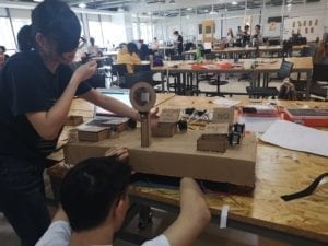
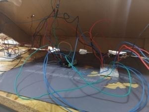
During the user testing session, lots of people did not know how to use it at first, only when we gave the instruction would they feel interesting. However, it was clear that the implication of using methods is not obvious enough for users to interact with it. We implement the advice to replace the button with a distance sensor, change the look of the microphone, and also let the boxes open by itself. These suggestions are all given by the users during the user testing session, which makes a great improvement to let the user better interact with our device. First, we used to let the button become a controller of the whole circuit, which means the user needs to keep holding the button while they are asking the question. As we replace the button with an infrared ray sensor, it will automatically start and stop while it detects the distance is close enough (inside of a range). Second, the shape of the conch is somehow misleading. The user may won’t connect it with the Magic Conch in the Sponge Bob, or even didn’t see the Sponge Bob before. But the look of the old microphone itself has a strong implication for the user that here is the place to talk and ask the question. The infrared ray sensor is stuck on the microphone to detect the distance and also look better. Third, we add the servo on the side of the box to let the cover open automatically instead of letting the user open it. We also add one more box into the device, which contains a few chocolates in the “enjoy it” box. The aim of us is to let the user has some reflections after receiving this answer. It may be unexpected and reveal a new way for them to deal with the trouble, or it may be what they thought before, and confirm their confidence.
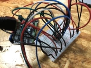
We had lots of troubles when we were working on this project besides the unclear implication of the look of the device. Since we had five boxes, we need surplus power to run those servos. However, we burnt one because we didn’t know the servo was driven by 5V power. Later, we found that the Arduino board is not powerful enough to drive one servo and two sensors. This problem was not identified during the presentation session so that we could only act by ourselves. Meanwhile, the connection between the cover, the box, and the servo is not delicate and strong enough.

Linking back to my own definition of interaction: a procedure of two or more objects affecting each other in various ways in a short period of time. I let the box with certain answer open after I asked the question, as well as the answer is given by the box makes me reflect on my decision and my question itself. In the user testing session, the user also asked some questions they really care about and was surprised by the answer given. The device itself is not only cool but also reflective. However, because of our failure in circuits, the experience of the user is not as perfect as I expected before. This also teaches me a lesson that I should test the circuit much earlier than the deadline so that we can find out whether there are any potential problems. Because in our expectation we didn’t suppose the Arduino kit cannot drive a servo and both sensors, we built up outside fabrication part and then the circuit, which was really late, just before the presentation session. If we do have more time, we will improve it by adding more answers (boxes), let the connection between the box and the cover more stable, and also let more people try the device and provide feedback.
However, the device was finally working on Friday, after fix and repair. I was astonished by the answer “enjoy it” when I asked my question “what is my launch today?” I suddenly remembered our initial motivation for making this device: to inspirit the user to find a way of solving their problems. So I went downstairs to grab a grilled cheese, one of my favorite food, as my launch that day.

It gave me inspiration and some suggestions for my future decision. Though whether to follow its suggestion or not is my own decision, we can not deny the huge possibilities of people being inspired by the device. The reflection of our answers, decisions, and also questions may also influence our behavior. However, I also hope that people can be joyful when they receive the unexpected answer, eat that chocolate, and live their lives happily without hesitating for their decisions.

References:

Crawford, Chris. “Art of Interactive Design.” Art of Interactive Design | No Starch Press, nostarch.com/interactive.htm.

https://www.creativeapplications.net/scripts/biy-believe-it-yourself-real-fictional-belief-based-computing-kits-by-automato/

https://books.google.com.hk/books/about/The_Book_of_Answers.html?id=xHlN3wrJfEsC&source=kp_book_description&redir_esc=y

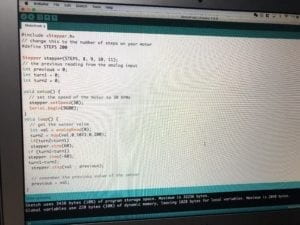
The code is attached as following:

#include <Servo.h>

Servo myservo;

int VIPin = A0;
int DIPin = A1;
int DisThreshold = 80;
int V_upper_bound = 127;
int PinOut[] = {3,5,6,9,10};

void setup() {
Serial.begin(9600);
}

void loop() {
//Generate a box number according to the audio received.
int DisInput = analogRead(DIPin);
int BoxNumber = 0;
int Tri = 0;

if (DisInput >= DisThreshold) {
Tri = 1;
}else{
Tri = 0;
}
while (DisInput >= DisThreshold) {
int VoiceInput = analogRead(VIPin) % 5;
BoxNumber += VoiceInput;
DisInput = analogRead(DIPin);
delay(10);
}

if (Tri > 0) {
BoxNumber = BoxNumber % 5;
myservo.attach(PinOut[BoxNumber]);
Serial.println(PinOut[BoxNumber]);
delay(3000);
myservo.write(120);
delay(7000);
myservo.write(0);
}else{
myservo.attach(3);
myservo.write(0);
myservo.attach(5);
myservo.write(0);
myservo.attach(6);
myservo.write(0);
myservo.attach(9);
myservo.write(0);
myservo.attach(10);
myservo.write(0);
}

delay(1000);
}

Recitation 4: Drawing Machine by Jiahui Zhang

Introduction:

I was supposed to create a drawing machine with my partner Hanqi Deng by using an H-bridge to control stepper motors attached to mechanical arms. Unfortunately, because of the wrong connection in Deng’s Arduino, her circuit burns. So I use my circuit and Clover Li’s circuit building a drawing machine at the end.

Materials:

For Steps 1 and 2

1 * 42STH33-0404AC stepper motor
1 * L293D ic chip
1 * power jack
1 * 12 VDC power supply
1 * Arduino kit and its contents

For Step 3

2 * Laser-cut short arms
2 * Laser-cut long arms
1* Laser-cut motor holder
2 * 3D printed motor coupling
5 * Paper Fasteners
1 * Pen that fits the laser-cut mechanisms
Paper

Step 1: Build the Circuit

H-bridge circuit diagram

The diagram for the circuit is here. It is a little complex at the first glance, but it will be much easier to figure out what is going on if using different colors for specific functions. 42STH33-0404AC stepper motor has 4 wires to connect and also both 5V and 12V will be connected to the circuit. So we need to be really careful about that. The advises given by LA are to separate the 5V part from the 12 V part on the breadboard so that even if you connect it wrong, it won’t burn, and also pay attention to the place of semicircle on the H-bridge. Because of that danger (for Arduino), I double checked the circuit before I plug in. However, my partner Deng unfortunately built a wrong circuit and plug into the USB port without double check. She burnt her Arduino so that I could only finish the rest by myself and borrow another circuit from other group to build the drawing machine.

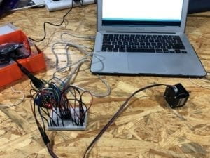
This is the circuit with complex wires.
Step 2: Control rotation with a potentiometer

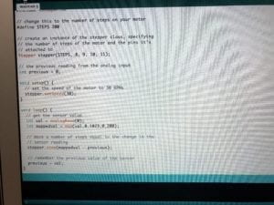
After adding a potentiometer to the circuit to read analog input, I use map to connect the potentiometer with the motor to control the motor. Then, I upload the MotorKnob (Arduino>File>Examples>Stepper>MotorKnob) example,modifying the number of steps within the code to 200, because the 42STH33-0404AC Stepper Motor is a 200 step motor. 

I change the code a little bit to better fulfil the requirement of step 3, which is building the drawing machine.

Step 3: Build the drawing machine

After the step 1&2, it’s much easier since I only need to borrow a circuit (since my partner’s one is burnt) and connect the Laser-cut arms and pen holders with paper fasteners. 

Here is my final work and the drawing!

Question 1:

What kind of machines would you be interested in building?Add a reflection about the use of actuators, the digital manipulation of art, and the creative process to your blog post.

I would like to build a device that can bring audience some inspirations that they never think about before or some ideas that answer to their problems. After the building several circuits and learn about some other interactive art pieces, I feel like what is different in interactive devices from the normal machine is the inner ideas brought up by the interactive devices when they respond to your actions. The actuators are just a tool for your final project. Without any meaning, it’s just a component of a circuit. However, the ideas brought up may be an inspiration, an answer, or even a question, or something you never expected. So I’m really interested in building a machine that can answer your question in an unexpected way. It may bring you a new way. 

Question 2:

Choose an art installation mentioned in the reading ART + Science NOW, Stephen Wilson (Kinetics chapter). Post your thoughts about it and make a comparison with the work you did during this recitation. How do you think that the artist selected those specific actuators for his project?

Waves built by Daniel Palacios in 2006 is one I feel interesting. It is a device that using motors to rotate an elastic rope to create complex sound and visual wave oscillations based on the audience’s motions. Regular sine waves is the respond to simple motions, and complex motions will create a more chaotic patterns for motor rotations. It is a device that has monitor to detect audience respond, which is more automatically interactive in comparison with the drawing machine we built, which also use motors but is controlled by potentiometer in a less automatic way. 

I think the artist first has the initial motivation before his start. In this case, it’s the linkage between our motions with the visible sound, which we never thought before. After find out this motivation, the artist choose the motor and elastic ropes to visualize the wave of sounds. 

Group Research Project: Individual Reflection by Jiahui Zhang

Reflection:

Interaction is a procedure of two or more objects effecting each other in various ways in a short period of time. If we split that procedure into closer details in a simple way, it is like what Igoe and O’Sullivan define in Introduction to Physical Computing—interaction is “listening, thinking, and speaking” in human terms from Chris Crawford’s perspective and “input, processing, and output” in computer terms (XX). However, an interactive device must be able to change its output as long as the audience changes its alterable input, while the algorithm is fixed. This definition is enhanced by our group project of the 2119 interactive device and the two projects—Blackberry Winter and BIY™—I found on the Creative Application.

BIY™(Believe it Yourself), created by Shanghai-based design studio Automato.farm, are three different kinds of real-fictional belief-based computing kits. Basically, the kits are using traditional Chinese Geomancy and Fengshui, which is based on rules of positions of mountains and rivers nearby, to tell the fortune. There are three kits that are BIY.SEE, BIY.MOVE and BIY.HEAR. By using the camera in BIY.SEE, users are able to see luck based on their conditions. Meanwhile, BIY.HEAR enables you to learn your destiny by microphone interpretation, and BIY.MOVE is a compass to post out your harmony and balance. Since the personal information and the location is alterable, the output will change while the user changes. The kits Believe it Yourself can be considered as an interactive device that involves “input, processing, and output”. 

Believe it Yourself.

On the other hand, Blackberry Winter is an artificial human motion in asymmetry. It is “an investigation into the possibilities of identifying motion as a continuous walk in a latent space of situations”. Using a machine learning solution to combine spatial information into a technical network weaving various and huge amount of motions by human bodies, the team created a visualized model to develop artificial human motions. From my perspective, Blackberry Winter is hard to be defined as interactive. Firstly, when the algorithm is fixed, the output won’t change while the input is altered. This means that it is like a fixed video showing in front of the audience, instead of a device that you can play with. Secondly, comparing the differences between Blackberry Winter and the Believe it Yourself, we can see that it is important for an interactive device to be useful—in other words, let the changes in input and output being useful. If we categorize Blackberry Winter as a kind of art, it is not reflective as most of the moves are unable for the human to perform.

 Blackberry Winter.

After understanding the idea of interaction, we started our group project “Disaster Jacket”, a life preserver in 2119, when natural disasters, like a typhoon, air pollution, earthquake, and other extreme weather, become more likely to happen. We set the scenes and performed the reaction of people with and without the Disaster Jacket to illustrate the function of the life preserver. It has multiple sensors detecting the environment (temperature, moisture, height, position, etc.) around you so that when natural disasters come, it can immediately produce the output. By dropping down the anchor, it can protect you in the typhoon. When you are drowning, the jacket will inflate and activate a light to alert rescue workers to your location. The jacket is defined interactive because it fulfills the criteria of following the procedure of “input, processing, and output”. Meanwhile, it is able to change its output when the environmental inputs change, while the algorithm is fixed. Related to the two projects I researched, the life preserver is useful and meaningful in the age of 2119. The device is focusing on human and user situations, avoiding people to get injured or even die in future natural disasters. This might be a real product in the near future as we already see interactive helmets protecting cyclers’ head when he falls off the bike.

  Our Group Project

References:

Crawford, Chris. “Art of Interactive Design.” Art of Interactive Design | No Starch Press, nostarch.com/interactive.htm.

https://www.creativeapplications.net/openframeworks/blackberry-winter/

https://www.creativeapplications.net/scripts/biy-believe-it-yourself-real-fictional-belief-based-computing-kits-by-automato/

Recitation 3: Sensors by Jiahui Zhang

Introduction:

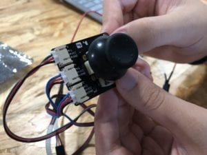
In this recitation, we still worked in pairs and built the circuit. I built the circuit connecting with the Joystick Module with my partner You Xu. The analog Joysticks provide two analog input: x and y, and one digital input: z. The most common use of joysticks we see is on the PlayStation as a controller for direction. It provides the most direct feedback as you move the joystick with your thumb.

Building the circuit:

We first decide to try to connect the analog Joystick like the instruction given by Brainy Bits (Here is the link: https://www.brainy-bits.com/arduino-joystick-tutorial/)

One problem I met during the coding was the Serial. begin used in the example was Serial.begin(115200);, but we need to use Serial.begin(9600);. My partner pointed that out and we fixed the problem.

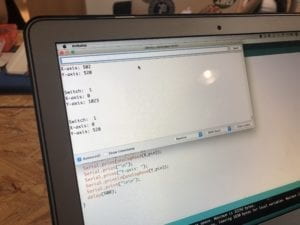
We ran the code and tested it that it actually worked. As we switch the stick and change its direction, the analog reading input number of x and y changes. And when we put the button, the input z, which is defined as “switch” will turn to 0 from 1.

We then decided to connect a LED and a buzzer to the circuit as outputs. 

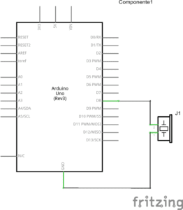
The LED is controlled by the z (switch). Meanwhile, the buzzer is controlled by the input x. As long as we move the joystick to the left side, the buzzer will ring the melody (because the input x will be greater than 1000). 

How the LED and the buzzer work.

We referred to the example “toneMelody” from Arduino Example library and also the lecture we learned before about how to turn the light on in certain conditions (the if sentence).

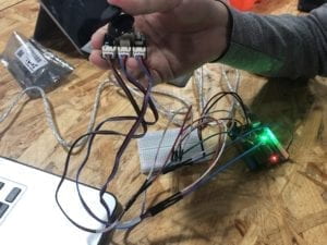
Since the Joystick has three input, we decided to add one more component for the output controlled by y. We connect the motor to the circuit and change the code to let the angle of the motor moving correlated to the input y. (Here we referred to the professor’s note of lecture 6).

How the motor works.

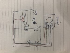
And this is the diagram of our final circuit.

Following is our code.

#include “pitches.h”
#include <Servo.h>
Servo servo;
const int SW_pin = 2; // digital pin connected to switch output
const int X_pin = 0; // analog pin connected to X output
const int Y_pin = 1; // analog pin connected to Y output
int melody[] = {
NOTE_C4, NOTE_G3, NOTE_G3, NOTE_A3, NOTE_G3, 0, NOTE_B3, NOTE_C4
};

// note durations: 4 = quarter note, 8 = eighth note, etc.:
int noteDurations[] = {
4, 8, 8, 4, 4, 4, 4, 4
};

void setup() {
pinMode(SW_pin, INPUT);
pinMode(3,OUTPUT);
digitalWrite(SW_pin, HIGH);
Serial.begin(9600);
servo.attach(9);
}

void loop() {
int yeah = digitalRead(SW_pin);
int no = analogRead(X_pin);
int okay = analogRead(Y_pin);
Serial.print(“Switch: “);
Serial.print(digitalRead(SW_pin));
Serial.print(“\n”);
Serial.print(“X-axis: “);
Serial.print(analogRead(X_pin));
Serial.print(“\n”);
Serial.print(“Y-axis: “);
Serial.println(analogRead(Y_pin));
Serial.print(“\n\n”);
if(yeah == 0){
digitalWrite(3,HIGH);
}else{
digitalWrite(3,LOW);
}
delay(50);
if(no > 1000){
for (int thisNote = 0; thisNote < 8; thisNote++) {

int noteDuration = 1000 / noteDurations[thisNote];
tone(8, melody[thisNote], noteDuration);

int pauseBetweenNotes = noteDuration * 1.30;
delay(pauseBetweenNotes);
// stop the tone playing:
noTone(8);}
}else{
noTone(8);
}
int mappedokay = map(okay,0,1023,0,180);
servo.write(mappedokay);
delay(50);
}

Question 1:

We intended to create a device that involved multiple outputs in different forms (like sounds, lights, and motions). If our sensor/actuator combination will  be used for pragmatic purposes, people with disabilities in hospital may use it, since they can light up the light by simply pressing a button, and with that same stick, they may control the wheel (or curtain) by the motor. Meanwhile, they can all the nurses in emergency as the set has a buzzer.

Question 2:

I think code is different from the recipe. If you don’t follow the recipe completely, the output (the dishes you make) may still be delicious. But if you write the wrong codes, the output will not even emerge. Meanwhile, it is more likely to an illustration for the machine, since code can be understood as a language both computer and human can understand.

Question 3:

The influence of new media brings a huge impact, or we can say improvement in automatic field, which influcences human social activities, learning, and all perspectives of life in a broader concept. We can see nowadays that the change brought by computer has already been significant in the SNS. Instagram, Twitter, Facebook, and all the interactive, online social way changes our way to make friends and keep contacts with our friends.

Recitation 2: Arduino Basis by Jiahui Zhang

Overview:

In this recitation, we build four circuits (three required & one optional) in pairs. I worked with Jackson. The first two was quite easy, and it got harder when it came to the third one as the wires needed increasing, but we still dealt with them.

Materials:

From Arduino Kit:

1 * Arduino Uno
1 * USB A to B cable
1 * breadboard
1 * buzzer
2 * LEDs
2 * 220 ohm resistors
2 * 10K ohm resistors
2 * pushbuttons
A handful of jumper cables

From cart:

2 * arcade buttons
1 * Multimeter (optional)

Circuits 1: Fade

The first one was quite easy as we had already done it in class before, just connecting the wires with the digital output on the Arduino board, the 220 ohm resistor, the LED, and the ground.

This was the circuit we made.

When we ran the Code: Arduino>File>Examples>03.Analog>Fading,the light started to fade.

Circuit 2: ToneMelody

This one was also easy to build. The melody was really funny so I changed the code to loop part so that we could record it more easily.

2
toneMelody

This is the one with the original code. This is the one with the repeated melody.

Code: Arduino>File>Examples>02.Digital>toneMelody

Circuit 3: Speed Game

This one is harder because the connection of the circuit is much more complex than the other two. Also, at the first time, we could not recognize the 10K resistor because the diagram seemed to be different from the diagram on the package. We asked the LAs, and they told us that we could see the detailed information and illustrations on the tinkercad if we registered and logged in. 

This is the diagram on the Tinkercad.

We forgot to draw our own schematic at first.

But we still made it work.

This is the process of our work.

The monitor showing it working.

IMG_The first try.

But we got a problem in the first run. We built the LED in the opposite way so that when the player one wins the game, the light won’t be on. We found the problem and fix it.

IMG_The second try.

It was quite fun, and the code was provided by the Tinkercad so we did not need to worry about coding.

Circuit 4: Optional four-player Speed Game

We changed the code a little bit. It was not hard as the basics were provided. We only needed to add the definitions and running codes for the player 3 & player 4.

These were the codes. These were the circuits we made.

It was a little bit complex as there were too many wires involved.

Question 1:

I have the same understanding as to the text Physical Computing, the interaction is something about “listening, thinking, and acting” for human, and “input, processing, and output” for machines.

Question 2:

The push button does not have resistance or only have little resistance. If we don’t want the circuit burn, we should add the resistor.

Question 3:

If we made those 100,000 LEDs together, and made it as a board, connecting with sensors, CPU, and other components, we can make a computer. I would like to use that to build a mirror, which can reflect the change of lights and shadows when the interactor moves. So it could be an interactive settings, as we have the suitable codes and circuits for it.