Individual Reflection (Midterm) – Jackson McQueeney (October 22, 2019)

Midterm Project: Pianote – Jackson McQueeney – Marcela Godoy

CONTEXT AND SIGNIFICANCE

My definition of interactivity has evolved over the course of this class, but it essentially refers to communication between two or more actors, including machines and humans, in the form of inputs and outputs. During the first group project, my group’s idea focused almost entirely on the interactive aspect of design, without considering if the design was even useful. However, for the midterm project, my partner and I designed a product that is both interactive and useful. Our project, called the “Pianote” was a piano that could teach the user how to play piano, based on the ability of the user to accurately respond to the notes that the program prompted. While its free-play mode was basically just a keyboard, the interactive aspect is present in the learning mode, offering a new degree of interactivity to a traditional keyboard. This project was aimed at those who want to learn how to play music.

CONCEPTION AND DESIGN

As I said before, the Pianote (as a prototype) is a seven-note keyboard with two modes. One of these modes, free-play mode, allows the user to play anything they want to play. The other mode, learning mode, teaches the user to play “Twinkle, Twinkle”. The Arduino was hidden inside of a laser-cut box, and the a breadboard was mounted to the top of the box. The following image is of this box’s SVG file:

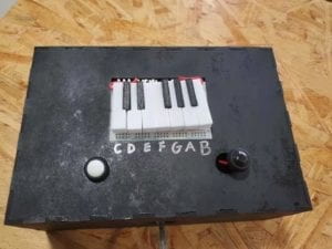
A series of flat wires connected the buttons on the breadboard to the Arduino. A set of 3D-printed piano keys were secured to the tops of the buttons, so the keys functioned more or less as regular piano keys. In terms of hardware design, the project was rather straightforward. However, the software facilitated its interactivity. One button corresponded to free-play mode, while the other corresponded to learning mode, and the user could freely switch between modes. In learning mode, the user, when prompted, would tap a key. If done correctly, they would learn how to play “Twinkle, Twinkle” on a keyboard. However, if the user incorrectly played a key, the software would correct them. 
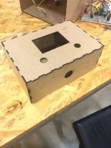
This is the laser-cut apparatus, made following suggestions from the user test, before the application of paint and insertion of the Arduino. The following image is the finished product:
FABRICATION AND PRODUCTION

The project was not entirely ready for the user test, as there were still problems with the code. However, we did receive useful feedback, including suggestions on how the software could hypothetically operate. Conceptually, the software aspect was simple to explain to users even though it did not yet work properly. When the user selected learning mode, the serial monitor would continuously loop the first prompt from that mode.

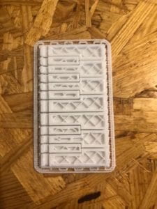
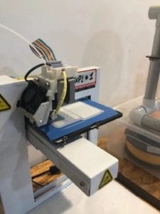
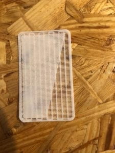
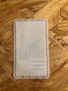
Most user critiques and suggestions regarded the hardware. In the original prototype, the laser-cut box had not been made yet, and we substituted it with a cardboard box. During the user tests, users found this to be rather unsightly and structurally unsound, so the laser-cut box was a definite improvement. Also, the original design indicated which key corresponded with each note on the serial monitor. For example, it would refer to the “C” key as the “key on the far left”. Users found this cumbersome, so we instead labelled the keys on the physical device. Additionally, in retrospect, one improvement that could have been made to the project would be the fabrication of custom buttons, that would more accurately function as piano keys. The fabrication of keys using the 3D printer presented some challenges. As the keys were printed, the corners of the mat would lift off of the print surface, and this happened after we replaced the tape as well. We asked the lab manager for assistance, so he switched the print material. However, the same problem arose. The first three of the following images is a different attempt with the same 3D printer. The last image is of the mat lifting off of the print surface:
CONCLUSIONS

This project sought to teach musical beginners how to play piano in an interactive way. In the regard that interaction is the communication of two or more actors through the medium of inputs and outputs, I believe that our project is interactive. While not necessarily misaligned with my definition of interaction, I believe that some aspects of the project would be better suited as hardware rather than software. Specifically, I think initial basic instructions would be better as a part of the physical device. Users (at least after the user test) generally interacted with our project as intended. They would read the prompt for their desired user mode, and then would generally not have any issues following the prompt on the serial monitor. However, one improvement  I would be interested in pursuing would be implementing the use of LEDs to indicate which keys should be pressed. Rather than reading instructions from the serial monitor, the user could react to an activated LED in real time.
Recitation 4: Drawing Machines (October 8, 2019) by Jackson McQueeney

Overview

For this recitation, I first built a circuit to run a stepper motor using an H-bridge. Then, I made the motor controllable with a potentiometer. Finally, my partner, who built his own stepper motor circuit, and I combined our circuits to make a drawing machine. 

Materials

For Steps 1 and 2

1 * 42STH33-0404AC stepper motor
1 * L293D ic chip
1 * power jack
1 * 12 VDC power supply
1 * Arduino kit and its contents

For Step 3

2 * Laser-cut short arms
2 * Laser-cut long arms
1* Laser-cut motor holder
2 * 3D printed motor coupling
5 * Paper Fasteners
1 * Pen that fits the laser-cut mechanisms
Paper

Step 1

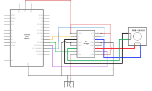
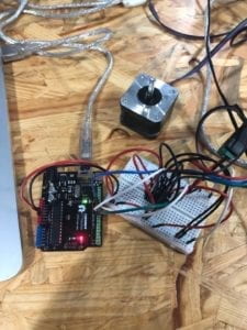
For this step, I had to make a stepper motor oscillate using an H-bridge. Even though the H-bridge required many connections, the circuit diagram was relatively straightforward and I was able to make most of the connections without issue. However, I did need to ask for help with the VCC2 connection. After that, I ran the code and the motor functioned as intended. 

Step 2

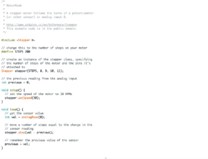
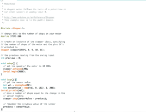
At this point, I had to add a potentiometer to the circuit so I could control the movement of the stepper motor. Adding the potentiometer to the circuit was not difficult, but writing the code to make it control the motor was (I noticed my partner having the same issue on his code. We asked for help from a learning assistant, who laughed at us, and then a professor pointed out that we had to map the value of the analog input to the stepper motor’s movement. After we fixed this, we were able to move on to step 3.

Step 3

Now, my partner and I were able to work together to make the drawing machine. We put the motors in a laser-cut template, and attached the 3D-printed arms. We each independently controlled our own potentiometers to  draw on the paper. The motors and drawing apparatus worked well enough, but sometimes the pen fell out of the arms.

Question 1

What kind of machines would you be interested in building? Add a reflection about the use of actuators, the digital manipulation of art, and the creative process to your blog post.

If I had the technical skill, I would be interested in building a humanoid robot. I think the versions of this machine that I have seen possess an interesting combination of motorized mechanical movements, similar to the drawing arms (though on a larger scale), and programmed stimuli and responses. This combination could be used for many different applications, including digital art, since the robot could be programmed to respond to inputs by painting, singing, talking, or any other output.

Question 2

Choose an art installation mentioned in the reading ART + Science NOW, Stephen Wilson (Kinetics chapter). Post your thoughts about it and make a comparison with the work you did during this recitation. How do you think that the artist selected those specific actuators for his project?

I think Douglas Irving Repetto’s Giant Painting Machine/San Mateo was very similar to our drawing machine project, in terms of both projects consisting of a motor moving some drawing device across a blank canvas. However, they are different in that Repetto’s project relied on randomly generated, erratic changes in the code’s variables to change speed and direction, whereas our drawing machine was directly controlled by two users. I think Repetto chose his actuators based on what would cause the most erratic movement, since he was attempting to physically generate completely random lines of paint. 

Individual Reflection (Group Project) – Jackson McQueeney (September 27)

Throughout my time in this class, and in light of our readings and this group project, my definition of interactivity is the communication between two actors that can receive inputs and produce outputs, so that each can respond to and influence the other. In “The Art of Interactive Design”, Crawford defines interaction “in terms of a conversation: a cyclic process in which two actors alternately listen, think, and speak (1)”. These actors, in my opinion, can include any combination and any number of people and computers. 

I think this project aligns well with my definition of interactivity. Besides the programmers who created the drones to collect data, the project also employed the use of cyclists to collect data on air quality. Whereas other methods of data collection regarding air quality focus on horizontal distribution of atmospheric pollution, this project employs the use of drones to account for the vertical dimension. The main actors are the sensors that gauge air quality, the programmers, and the cyclists, and the drones. The sensors on the drones respond to the instructions of the programmer, and then they relay the data that they collect to the programmer. Likewise, the cyclists act as a sort of organic drone, transporting the sensors around the city in order to collect more data.

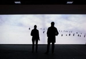
This project, contrarily, does not align very well with my definition because it seems to be an art installation that happens to the user. That is to say, the actions of the user do not affect their experience. To clarify, there are interactive aspects of this project, but the communication takes place between two human actors that do not physically see each other. Rather, the actions of one human actor will influence the output of the computer for the next human actor. In short, two human actors interact through the medium of the computer. To think of this project another way, Crawford posits that interactivity can and should be measured on a spectrum (6). Whether this project is interactive should not be a question of ‘yes’ or ‘no’, but rather a question of high interactivity, moderate interactivity, low interactivity, and everything in between. In my opinion, using Crawford’s approach, this particular project has low interactivity.

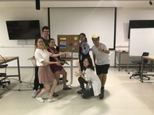
For the project, my group wanted to develop an idea that might be relevant one hundred years in the future. We eventually decided on one idea, a watch that would utilize sensors to collect data on the user’s heart rate and body temperature to determine the user’s mood. The watch would then communicate this determination to a computer, which would compile the user’s mood throughout the day and compose a painting using colors assigned to given moods. Additionally, the watch would record the distance and speed of the user while walking to determine the size of the brushstrokes in said painting. The actors in this interaction are the user, the watch, and the computer. The user “communicates” (through their actions rather than their words) with the watch, which then transmits these inputs to a computer that produces an output for the enjoyment of the user. In this regard, I believe our project had a moderate to high degree of interactivity. 

Works Cited

Crawford, “What Exactly is Interactivity,” The Art of Interactive Design,  pp. 1-5.

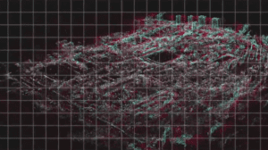
https://www.vice.com/en_us/article/593xxa/drones-augmented-reality-cities-map-air-pollution

‘Ghost’ installation traps visitors in an interactive snow storm

Recitation 3: Sensors (September 21, 2019) by Jackson McQueeney

Overview

For this recitation, my partner and I chose from a variety of sensors to create our own circuit. We also chose our own outputs. We decided to use a vibration sensor, which would trigger an LED to light up and a buzzer to sound once activated. 

Materials

1 Speaker
1 LED
1 Vibration Sensor
2 1 MΩ Resistors
1 10K Resistor

Circuit: Vibration Sensor


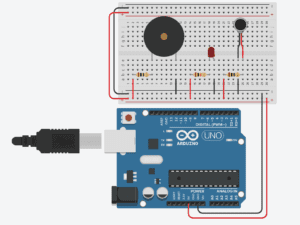
(This schematic of our circuit uses a vibration motor to represent a vibration sensor because Tinkercad does not have a vibration sensor)

Our circuit consisted of a speaker, an LED, a vibration sensor, 2 1 MΩ resistors, and a 10k resistor. The LED and vibration sensor functioned as intended after we put the circuit together, but the speaker did not function when triggered. After getting help from a professor, we found that this was a problem with the code. We had not properly coded the tones that the speaker was supposed to play, so the speaker just played a static sound instead. After this issue was resolved, the circuit worked and detected vibrations would trigger the LED to light up and the speaker to sound.

Question 1

Our assembly was not intended for a real-world application, since it was built simply to make lights and sounds when vibrations were detected.

Question 2

I think code is compared to recipes and tutorials because the computer uses code as a guide to function. Everything that a computer does is based on some instruction given directly by a code. 

Question 3

I think that computers in the modern world serve to enhance our daily lives in different ways. I consider them to be supplements to our daily lives, and because of this, they have a huge influence on what we do. Especially in the context of social media, which I think fosters more interpersonal connections than have ever been possible at any other point in our history.

Recitation 2: Arduino Basics (September 11, 2019) by Jackson McQueeney

Overview

During this recitation, my partner and I built three different circuits, this time with our own Arduino kits. The first circuit was called “Fade”, and consisted of an LED which was programmed to fade between high and low brightness at a regular interval. The second circuit was called “toneMelody”, which included a speaker that played a sound that my partner and I told it to play. The third circuit was called “Speed Game”, which was a two-player game in which players attempted to press the button the most times in a certain time interval. The first two circuits were fairly straightforward, but we needed help writing the code for the second circuit. The third circuit was both difficult to construct and difficult to program, but with assistance we were able to complete it.

Materials:

1 * Arduino Uno
1 * USB A to B cable
1 * breadboard
1 * buzzer
2 * LEDs
2 * 220 ohm resistors
2 * 10K ohm resistors
2 * pushbuttons
A handful of jumper cables
2 * arcade buttons

Circuit #1: Fade

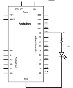
This circuit consisted of the Arduino, a breadboard, a 220 Ω resistor, an LED, and wires. We first connected the LED and the resistor in the breadboard, then we connected the resistor to power from digital pin 9, then lastly we connected the LED to ground. This circuit worked without issue.

Circuit #2: toneMelody

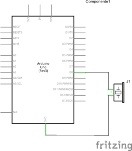
This circuit was similar to the first one, but there was no resistor. We connected the speaker to digital pin 8 and ground, and the circuit functioned properly.

Circuit #3: Speed Game

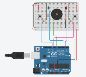
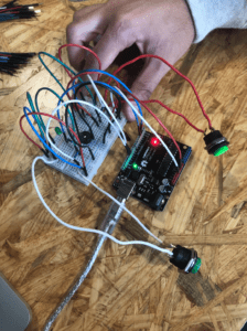
This circuit was difficult to build compared to the other two, as it consisted of many more parts. This circuit contained two arcade buttons, a speaker, two LEDs, two 220 Ω resistors, and two 10K resistors. After we finished building it, my partner and I uploaded the code and tested the circuit, which worked. 

Question 1:

Based on my experiences in this class, including recitations and the readings, I would define interaction as a process of inputs and outputs exchanged between two actors. In this case, actors include humans and machines. Specifically, an interactive design is one in which the output of a machine is influenced directly by the input of a human actor, and a machine’s collection of input data is influenced by the labor output of a human. These actions are reciprocal, and each depends on the other for a design to function.

Question 2: 

The 10K resistor controls the the current in the circuit. Since five volts are flowing through the circuit, and that voltage would overload the button, the resistor protects that component of the circuit.

Question 3:

If I had 100,000 LEDs, I would donate them to the IMA lab so that future students have the resources to learn how to build circuits.