Final Project: Final Blog Post (December 18, 2019) – Jackson McQueeney

Vocal Art – Jackson McQueeney – Marcela Godoy

CONCEPTION AND DESIGN:

After discussing our six ideas, my partner and I decided that “Vocal Art” would not only be the most realistic project to execute, but it would also best fit our definitions of interaction. The conception of this project was simple, especially in the way we foresaw users interacting with it. Since the main component of this project was a microphone, we decided that the physical aspect of the project should be an intuitively-designed microphone.

Additionally, we decided to add three potentiometers—each controlling one RGB color value—to add another layer of interactivity. Since the overarching project idea was rather simple, it had a rather simple design. We housed the microphone and potentiometers in a laser-cut wooden box, with basic instructions and its function etched into the box. We tried to connect my partner’s computer to a large TV screen in order to display the output to a large audience, but due to technical difficulties, we were not able to achieve this. At one point, we affixed a cardboard cone to the microphone in an attempt to better receive sound input, but the cone covered the instructions, so we ultimately removed it. One suggestion made after we finished and presented the project was to put colored caps on the potentiometers, each corresponding to the red, green, and blue values that they controlled, but since this suggestion was made after our final presentation, we could not implement it.
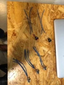

Potentiometers and buttons soldered for the circuit
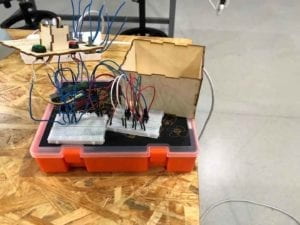

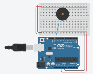
Complete circuit before being housed
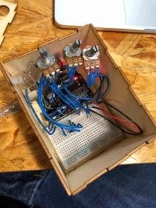

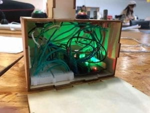
Two angles of the Arduino circuit housed in the box

Top of the wooden housing (Showing instructions, buttons, and potentiometers)

Video of the Processing code running after multiple microphone inputs

FABRICATION AND PRODUCTION:

After our initial conception and design phase, we built our project. The most significant steps of the process were constructing the Arduino circuit, writing the code for Arduino and Processing, and using digital fabrication to make components of our project. In the latter step, I believe the project could have been improved by elevating the microphone by fabricating a more appropriate housing and by including colored caps on the potentiometers.

Although I could not be present for the user testing session, my partner relayed to me some of the feedback that the project received. Two major aspects of the project were developed following this feedback, specifically placement of the output circles on the Processing screen and the use of potentiometers to control RGB values. From the feedback, we decided to make the placement of the circles random, and we incorporated potentiometers to control their RGB values. I believe that these changes were effective, since they added more dimensions of interactivity to the project, while keeping the overall concept simple and concise. 

CONCLUSIONS:

The broad goal of this project was to facilitate interaction between multiple users and the project. Specifically, the goal was to translate the users’ voices into a visual output that preserved outputs from previous uses after each subsequent use. Through this course and an ever-evolving definition of interaction, I currently define interaction as: “the communication between two or more organic or machine actors, facilitated by an interchange of inputs and outputs between actors”.

I believe that our project aligns with this definition in that it required the inputs of many human actors to achieve its full goal/effect in the form of its output in Processing. This translation from input to output was facilitated by the sound sensor in Arduino. This project does not align with my definition in that the inputs and outputs were not necessarily interchangeable, but I think that is a problem with my definition rather than a problem of the interactivity of the project. Based on this definitions and my expectation of the audience’s response, I believe that my audience interacted with the project in that they provided an input in the form of their voice, and the project generated an output based on the variable volume of each individual user, and I think that this form of interaction was exactly what my partner and I expected.

Based on audience feedback after our final presentation, I believe a few ergonomic/intuitive improvements could be made to the physical design of the project, had we more time. These include using a more sensitive microphone to pick up more nuanced volume differences between each user, elevating the box so that users do not have to bend over to speak into the microphone, using a different LED so that the color of the LED more accurately represented the color of the generated circles, and using colored caps for the potentiometers so that users could more easily determine their function.

One idea that I thought would be interesting (though difficult) to attempt would be to implement some sort of method to determine the user’s mood, and base the output on that rather than volume. Though this might be too advanced for our current ability, I think that our project could be improved by changing outputs based on pitch as well as volume, since pitch is easier to determine than mood.  With the completion of this project and course, I feel more confident in my coding abilities and my circuit-building abilities using Arduino. I think the most consequential outcome of this project was its simplicity. Many other projects, both during midterms and finals, had some big overarching moral message or attempted to solve some major global issue, ultimately losing some aspect of its interactivity. However, I believe our project was successful because it focused on the interactivity aspect.
Recitation 9: Media Controller (November 19, 2019) by Jackson McQueeney

Processing Code:

import processing.serial.*;

Serial myPort;
int valueFromArduino;
import processing.video.*; 
Capture cam;

void setup() {
  size(640, 480); 
  cam = new Capture(this, 640, 480);
  cam.start(); 

  printArray(Serial.list());

  myPort = new Serial(this, Serial.list()[2], 9600);
}


void draw() {
  // to read the value from the Arduino

  while ( myPort.available() > 0) {
    valueFromArduino = myPort.read();
  }
  if (cam.available()) {
    cam.read();
  }
  
  image(cam, 0, 0);
  
  if (valueFromArduino > 200) {
    filter(INVERT);
    println(valueFromArduino);
  }
}

Arduino Code (Input)

const int ledPin = 3;     
const int sensorPin = A0; 

int value; 

void setup(){

  pinMode(ledPin, OUTPUT);  
  Serial.begin(9600);      
  
}

void loop(){

  value = analogRead(sensorPin);                 
  value = map(value, 0, 1023, 0, 255);
  Serial.println(value);      
  analogWrite(ledPin,255-value);          
  delay(100);                          
}

Arduino Code (Communication)

void setup() {
  Serial.begin(9600);
}


void loop() {
  int sensorValue = analogRead(A0) / 4;
  Serial.write(sensorValue);

  
  delay(10);
}

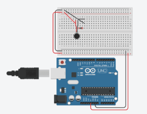
Arduino Circuit:

Result:

Upon activating the force sensor, the colors of the video input invert. 

In Computer Vision for Artists and Designers, the author discusses the application of technology in various fields not traditionally related to technology. Softwares like Processing allow a new focus on the potential visual applications of technology, specifically in the field of visual arts. My code used the computer camera in order to collect visual input, and used Processing’s language to invert the colors from this input. This inversion was activated by a force sensor that the user interacts with. 

Final Project: Essay (November 26, 2019) – Jackson McQueeney

Vocal Art (With Kevin Nader)

This project will make artistic interpretations of the user(s)’ voices, and it will base the color’s saturation on the volumes of the voices. The project will ideally translate the vocal input (from a microphone) into colors and shapes (again, based on volume). After one user uses the project, the interpretation of their voice would remain drawn on screen, and will be added to by the next user. 

This project aims to interpret the voices of its users, and compound these interpretations between each user. The first user would start with a blank canvas, while each subsequent use would build on top of that. The Arduino code will process input data and send it to processing, which will generate the output. This project does not require that much physical fabrication, the only physical component being the microphone Arduino circuit. Once this part of the project is complete, my partner and I will write the Arduino and processing codes. Given the simplicity of the physical aspect of the project, this could allow my partner and me to design an aesthetically-pleasing physical apparatus to house the circuit. 

Over the course of the semester, we have had to define and redefine “interaction” numerous times. I originally defined it as “the communication between two actors” for the group project, then changing it to “the communication between two or more actors through mutually influential inputs and outputs” for the midterm project. As of now, my definition is “the communication between two or more organic or machine actors, facilitated by an interchange of inputs and outputs between actors”. Interactivity relies on the mutual exchange of inputs and outputs between human and non-human actors. These updates to my definition were influenced by Crawford’s “The Art of Interactive Design”, in which he defines interaction “in terms of a conversation: a cyclic process in which two actors alternately listen, think, and speak (1)”.

Vocal Art aligns with my updated definition of interaction because it consists of a machine actor and potentially several human actors that consistently communicate and build upon previous outputs. My partner may have different ideas about this project’s significance, but I see it as a collaborative art piece that complicates itself and constantly changes based on its perception of its audience. I don’t think there is a specific intended audience, simply anyone who wishes to add their voice to the collective canvas.

Recitation 8: Serial Communication (November 12, 2019) by Jackson McQueeney

Part 1: Etch-A-Sketch

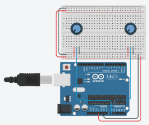
Arduino Schematic:

Arduino Code:

void setup() {
  Serial.begin(9600);
}

void loop() {
  int sensorValue1 = analogRead(A0);
  int sensorValue2 = analogRead(A1);
  int mappedvalue1 = map(sensorValue1, 0, 1023, 0, 500);
  int mappedvalue2 = map(sensorValue2, 0, 1023, 0, 500);
  Serial.print(mappedvalue1);
  Serial.print(",");
  Serial.print(mappedvalue2);
  Serial.println();
  delay(1);        
}

Processing Code:

import processing.serial.*;
String myString = null;
Serial myPort;
int x2;
int y2;
int NUM_OF_VALUES = 2;   
int[] sensorValues;      

void setup() {
  size(500, 500);
  background(0);
  setupSerial();
}

void draw() {
  updateSerial();
  printArray(sensorValues);
  stroke(255);
  line(x2, y2, sensorValues[0], sensorValues[1]);
  x2 = sensorValues[0];
  y2 = sensorValues[1];
}

void setupSerial() {
  printArray(Serial.list());
  myPort = new Serial(this, Serial.list()[5], 9600);
  myPort.clear();
  myString = myPort.readStringUntil( 10 ); 
  myString = null;
  sensorValues = new int[NUM_OF_VALUES];
}

void updateSerial() {
  while (myPort.available() > 0) {
    myString = myPort.readStringUntil( 10 ); // 10 = '\n'  Linefeed in ASCII
    if (myString != null) {
      String[] serialInArray = split(trim(myString), ",");
      if (serialInArray.length == NUM_OF_VALUES) {
        for (int i=0; i<serialInArray.length; i++) {
          sensorValues[i] = int(serialInArray[i]);
        }
      }
    }
  }
}

Result:

Part 2: Musical Instrument
Arduino Schematic:

Arduino Code:

#define NUM_OF_VALUES 2

int tempValue = 0;
int valueIndex = 0;

int values[NUM_OF_VALUES];

void setup() {
  Serial.begin(9600);
  pinMode(13, OUTPUT);
}

void loop() {
  getSerialData();


  if (values[2] == 1) {
    tone(9, values[0]);
  } else {
    noTone(9);
  }

}


void getSerialData() {
  if (Serial.available()) {
    char c = Serial.read();
    switch (c) {
      case '0'...'9':

        tempValue = tempValue * 10 + c - '0';
        break;
      case ',':
        values[valueIndex] = tempValue;
        tempValue = 0;
        valueIndex++;
        break;
      case 'n':
        values[valueIndex] = tempValue;

        tempValue = 0;
        valueIndex = 0;
        break;

      case 'e':
        for (int i = 0; i < NUM_OF_VALUES; i++) {
          Serial.print(values[i]);
          if (i < NUM_OF_VALUES - 1) {
            Serial.print (",");
          }
          else {
            Serial.println();
          }
        }
        break;
    }
  }
}

Processing Code:

import processing.serial.*;

int NUM_OF_VALUES = 2;

Serial myPort;
String myString;

int values[] = new int[NUM_OF_VALUES];

void setup() {
  size(500, 500);
  background(0);

  printArray(Serial.list());
  myPort = new Serial(this, Serial.list()[5], 9600);

  myPort.clear(); 
  myString = myPort.readStringUntil(10); 
  myString = null;
}

void draw() {
  noStroke();
  fill(0, 30);
  rect(0, 0, 500, 500);

  strokeWeight(5);
  stroke(255);
  line(pmouseX, pmouseY, mouseX, mouseY);

  values[0] = mouseX;
  values[1] = mouseY;

  sendSerialData();
  echoSerialData(200);
}

void sendSerialData() {
  String data = "";
  for (int i=0; i<values.length; i++) {
    data += values[i];
    if (i < values.length-1) {
      data += ",";
    } else {
      data += "n";
    }
  }

  myPort.write(data);
}

void echoSerialData(int frequency) {
  if (frameCount % frequency == 0) myPort.write('e');

  String incomingBytes = "";
  while (myPort.available() > 0) {

    incomingBytes += char(myPort.read());
  }

  print(incomingBytes);
}