Recitation 4: Drawing Machines by Jonathan Lin

Questions

  1. I would love to go more in-depth with the current idea of a drawing machine.  I am always enthralled by how steady the hands of artists are. I could never sit still for hours with steady hands to draw something that could be considered art. I would love to improve our current project to actually make a machine capable of drawing something beautiful with precision. Actuators are quite amazing if you think about it. It allows your projects to come to life because they become sort of like the legs to your product. They become legs because they allow the act of movement. Also, in our current world digital manipulation of art has become very proliferate. It can be used to enhance an already amazing piece of art or used to deceive. It can be an amazing supporting tool, or it can be used as a propaganda weapon. IMA is all about being creative because it allows you to explore. In order to make something new in a sea of used ideas, one must look towards the unexplored oceans. 
  2. Raffaello D’Andrea, Max Dean, and Matt Donavan’s The Table is a project that stands out to me. This project is truly a creative endeavor because who would ever think of an autonomous table? Comparing their project to our drawing machine, not only is their more complex they are also crazier. Crazy in a positive sense because when someone sees a moving table, I cannot imagine them not cracking a smile. The drawing machine is more of a practical robot, but a table that follows you around is just silly and amazing. The actuators that are making this project move must have been carefully selected. They were probably picked because they were able to support the weight, and their in-sync movement was natural. If you are going to have a moving table, you should make sure it’s movement is smooth, like someone is pushing it. 

Materials/Diagram/Code

For Steps 1 and 2

1 * 42STH33-0404AC stepper motor
1 * SN754410NE ic chip
1 * power jack
1 * 12 VDC power supply
1 * Arduino kit and its contents

For Step 3

2 * Laser-cut short arms
2 * Laser-cut long arms
1* Laser-cut motor holder
2 * 3D printed motor coupling
5 * Paper Fasteners
1 * Pen that fits the laser-cut mechanisms
Paper

H-bridge circuit diagram

Task 

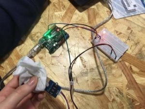
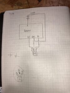
Step 1: Build the circuit

Build the following circuit to control the stepper. You can use the stepper_oneRevolution(Arduino>File>Examples>Stepper>stepper_oneRevolution) example code to get your motor to make one revolution. If done correctly, your motor should rotate smoothly. Make sure you orient the IC in the correct position; this can be seen in the Components section at the bottom.

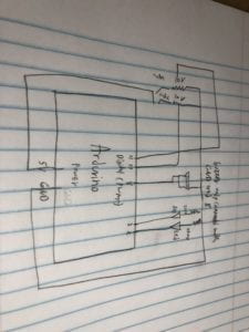
Step 2: Control rotation with a potentiometer

Add a potentiometer from your kit to the circuit in such a way as to allow you to read analog input. Then, upload the MotorKnob (Arduino>File>Examples>Stepper>MotorKnob) example  to control your motor. Please modify the number of steps within the code to 200, because the 42STH33-0404AC Stepper Motor is a 200 step motor. You can use the function “map()” in order to match the movement of the knob with the rotation of the motor.

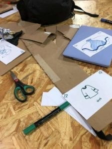
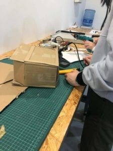
Step 3: Build a Drawing Machine!

Once you have your motor moving via input from a potentiometer, find another person who has also completed Step 2 and pair up with them. Collect the materials needed for Step 3 and combine your parts into a mechanical arm that can hold a marker on paper, as seen in the picture below. Use your potentiometers to make the motors turn and draw something.

Conclusion

The problem I had, in the beginning, was that I had to be very careful with following the diagram. One little mistake and I would have to backtrack a lot. After finishing the diagram, I tested it but it did not work at first. I thought maybe my code was the problem, but the reason why was because my H-Bridge was not fully pushed in the breadboard. After that, I partnered with one of my classmates. The drawing machine was pretty easy to assemble and we got it working pretty quickly. 

Recitation 4: Group Presentation (Jonathan Lin)

Our idea of interaction was very simple, but had to fulfill certain key requirements. The first requirement is that there must be at least two actors in an interaction. The second is that the two actors must be taking turns in engagement and must be reacting according to what the other is doing.  Lastly, there must always be a variability of outputs that vary depending on the input from the other actor.

Alias is a great example of interaction because it checks all these boxes, and more. The actors are clearly the humans and their personal parasites, and they both take turns in engaging with each other. For example, the human asks a questions and then waits for a response, or the human gives a command and waits for confirmation. The output variety of what Alias says is also shown in the video, as it only reacts to the given name you assign it. This allows the interaction to be different for all owners. An example of non interaction would be the EM table, where the actors are not interacting with each other. In short, the EM table, when turned on, transmits a small electromagnetic field around its center with the ability to power a low energy demanding light. This fails all of the check boxes, expect maybe having more than one actor, and also this aligns more with begin a battery source than interaction. If you consider this interaction, does charging your phone count as interaction too?

Using the above examples, we tried to incorporate the Alias style of interaction into our product. Our product the ClosetPod is interactive in more than one sense. Firstly, the first interaction is between the ClosetPod tablet and the person who owns it. This is because the ClosetPod not only can differentiate people with face identification, but also different people have different styles of clothing that they would install into their ClosetPod. The adaptive clothing that comes out of the Pod is also interacting, depending on the temperature and moisture of the atmosphere, it changes itself accordingly (like how our shirt became a raincoat in the rain) to fit it. How humans interact with the ClosetPod is similar to how you interact with your phone, where you request something and the tablet responds back. You would verify your face, the ClosetPod would confirm that face is yours, then you would go through your options of clothing and eventually pick one, where then you would wait for your ClosetPod to materialize it. Finally, the output of the ClosetPod, whether it being the clothing it materializes or the face it recognizes, is all dependent on the human user. This is due to the vary tastes of clothing and faces in humans, all of which are different variables that are taken in account that leads to different outputs.

The hardest task we had was definitely finding a way to present all the forms of interaction that the ClosetPod had to offer. Our group met up multiple times to discuss our skit because while we felt that we had a simple idea, expressing the many variables would be complicated. Eventually we decided that we could frame the product in a skit that is sort of a satire of our current lives. The idea being that 100 years later our technology is so advanced, but yet we still have not solved issues like global warming or poverty. We borrowed the idea of “broke” from the current Apple Airpods, where it is commonly joked that whoever has them are separated in social classes with others that do not possess them. This is due to the fact that these ear pods are ridiculously expensive, so the idea is that if you possess them you must have a lot of disposable income. Airpods are merely a convenient product, and I bet 100 years prior no one could ever imagine we would make them one day. This same concept is with the ClosetPod where it is merely a convenience.

All in all, we felt that we did a decent job at presenting our ideas, but there are a few things we could have improved in. The design in our product was something we could have definitely spent more time on. I think the cardboard box we used may have confused people because people are not used to tablets being that large and wide. Secondly, our skit could have put more emphasis on how interactive we truly imagined our product to be. And finally, I felt that the transformation of the tiny Airpod container into the large box might have been missed by a few people. We probably could have put more emphasis on that also. In conclusion though, this project has taught me a lot about interaction and makes me excited to looking towards our midterm and finals!

Here are some of photos of the skit and product making process:


Sources:

Alias – A teachable “parasite” for your smart assistant

Recitation 3: Sensors by Jonathan Lin

Questions

  1. My partner and I intended to assemble a circuit that used moisture as the trigger to light up a LED. We made it so that the LED would only light up after there was a certain amount of moisture present. That threshold of moisture was adjustable in our code. Our creation is pragmatic for example in buildings that are prone to flooding. When the sensors detect water they could automatically light up emergency lights to aid vision, or even power other objects like maybe a speaker. 
  2. The reason why code is often compared to following a tutorial is because you must follow the order. In functional code, you must go through the steps to get to the end product. For example, you must first declare your variables first before you use them, and same with your methods. Writing coding follows a timeline of steps. 
  3. The computer has definitively influenced our behaviors. Humans are creatures of mistakes, while computers are creatures of logic and perfection. Humans make mistakes, computers do not. When a computer makes a mistake it can always be traced back to humans. This idea of the computer has changed the behaviors of humans because now we depend on them. For example, with the invention of the computer it completely invalidates the typewriter. With the typewriter, if you made a mistake it would be extremely hard to undo that, but not on a computer. Computers have allowed humans to store mass amounts of data, so there is no more need to write everything down. The computer has made everything easier, and humans reliant on them.

Materials/Diagram

1 * Arduino Uno
1 * USB A to B cable
1 * breadboard
1 * LED
1* 220 ohm resistors
1*Moisture Sensor
A handful of jumper cables

Drawing drawn by my Partner: Jennifer Cheung


Task

For this recitation’s exercise, please work with a partner. Choose one of the sensors listed below and read about what it is and how it performs. Once you have picked a sensor, build a circuit that integrates this sensor with your Arduino. Use the data (input) from your sensor to drive an output (Servo-motor, LEDs, Buzzer, etc.). Document the finished circuit and your interaction with it. 

As you can see from the video below, our finished product was successful. The moisture sensor was easy to assemble because we learned how to assemble a servitor in class. After completing the circuit we begin to write the code, and after putting in a simple if/else we uploaded our code and tried to get the LED to light up. The serial monitor was sensing the moisture, but our LED was not working. Eventually we figured out the only problem was the polarity of the LED, and after we got that sorted out everything worked perfectly. The code is also attached below.

int sensorPin = A0;
int sensorValue = 0;
int ledPin = 9;

void setup() {
Serial.begin(9600);
pinMode(ledPin, OUTPUT);
}
void loop() {
// read the value from the sensor:
sensorValue = analogRead(sensorPin);
Serial.print(“Moisture = ” );
Serial.println(sensorValue);
delay(100);
if(sensorValue > 100)
{
digitalWrite(ledPin, HIGH);
}
else
{
digitalWrite(ledPin, LOW);
}
}

Recitation 2: Arduino Basics by Jonathan Lin

Questions

  1. The image of the computer has changed drastically throughout the decades. Back then, computers were these hulking machines that only spoke in text, but that was when Steve Jobs and Bill Gates revolutionized what a computer was. They made it something anyone could use, regardless if you knew how to code or not. This class is really awesome because it lets me glimpse into the olden days. I am not clicking an icon to make my LED blink or my buzzer beep. I am using code and building the circuit required to make all these things interact-able. In a tiny way, I am rediscovering what all these great minds before me have.
  2. If I had 100,000 LEDs I would make the roads of our dorms just a bit nicer. I know students like to go out during nighttime for street food, and the long driveway can get pretty dark at night. Therefore if I was able to light up the entire road leading to our dorm’s back gate it would be amazing. I could even fidget with the colors depending on the day. Maybe there could be some green and red on Christmas, or even  pink on Valentine’s Day. 

Materials/Diagram of Circuit 3

1 * Arduino Uno
1 * USB A to B cable
1 * breadboard
1 * buzzer
2 * LEDs
2 * 220 ohm resistors
2 * 10K ohm resistors
2 * pushbuttons
2 * arcade buttons
A handful of jumper cables
1 * Multimeter (optional)

Tasks

In a groups of two, build circuit 1, circuit 2, and circuit 3

Circuit 1: Fade (Success)

Thanks to the experience of last Recitation, my partner and I quickly sped through this first one with no problems. We quickly placed our 4 wires and then proceeded to find the code in examples. We uploaded it and the light faded as you see below. 

Circuit 2: toneMelody (Success)

At first we thought this was going to be more complicated, but we quickly figured out we only actually needed two wires to connect to the speaker. After powering the speaker we found the code, uploaded it and we heard this amazing jingle!

Circuit 3: Speed Game (Success)

This one took a bit longer, but we figured it out by working slowly. We first analyzed the model, and then slowly but surely all the pieces came together. After finishing the circuit, we just copy and pasted the code given and it worked. We only had one misstep which was when my partner and I misplaced a resistor leg, but that issue was resolved relatively quick with the help of a fellow. 


(Jonathan Lin) Recitation 1: Electronics & Soldering

Questions

  1. After reading the article, I see how much interaction we truly had put into creating this circuit. Not only were were my partner and I interacting at the beginning to figure out our plan, but our constant interactions with the circuit itself eventually led to an interactive final product. Our end products all required some interaction from an user, like pushing the button or twisting the knob. 

2. When you combine both of these elements you create something that must be considered art. Take for example the eye tracking writer, where not only is it art where it allows the user to express themselves, but also something practical that solves a real life issue. Sheer ingenuity allows something to become art, something everyone could interpret differently.  

Materials

  • 1 * Breadboard
  • 1 * LM7805 Voltage Regulator
  • 1 * Buzzer
  • 1 * Push-Button Switch
  • 1 * Arcade Button
  • 1 * 220 ohm Resistor
  • 1 * LED
  • 1 * 100 nF (0.1uF) Capacitor
  • 1 * 10K ohm Variable Resistor (Potentiometer)
  • 1 * 12 volt power supply
  • 1 * Barrel Jack
  • 1 * Multimeter
  • Several Jumper Cables (Hook-up Wires)

Tasks

Task 1: Build the circuits (Success)

With your partner, build Circuit 1: Door BellCircuit 2: Lamp, and Circuit 3: Dimmable Lamp on a breadboard based on the provided schematics. When you’ve finished a circuit, take pictures or film the finished circuit working. Record notes about the building process for each circuit, such as problems that you encountered, and how you fixed them.

Task 2: Switch the switches (Success)

During the recitation, you and your partner will be brought to soldering stations to learn how to solder. Here you will solder long wires to an arcade button.  Once you have completed this, you should replace the push button switch in at least one of the circuits you built with the newly soldered arcade button.

Circuit 1

In our first circuit, my partner and I first looked over the sketches and the parts to try to understand our task. Then, using our knowledge from the first two classes and help from the wandering instructors, we were able to slowly put the components together. The instructor gave us advice to start from the power source and go on from there. After we figured out where each component would be placed, the wiring came naturally. 

Circuit 2

Building from our first circuit, this one was pretty easy. This was because we already had the foundation placed, and all we needed to figure out was where to put the resistor in an already connected circuit. After replacing the speaker and moving some wires we were able to successfully light up the LED.


Circuit 3

Using the experience from our previous two circuits we build this one pretty quickly, but it wasn’t working. Not yet finished we were called to the back to solder a large button. After learning how solder, and with a new button in hand we tried to fix our circuit once more. After trying for a few more minutes, we eventually asked for help from another instructor, and found out our issue. When we replaced the LED we forgot about the polarity, after that our circuit was fully functional.