Recitation 3: Sensors by Serene Fan

Infrared Distance Sensor

Components

a buzzer

a breadboard

a Arduino uno

Jumper cables

a infrared distance sensor

Process

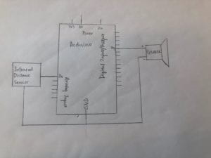
we use the speaker as the output. When a person gets closer to the sensor, the sound of the speaker becomes louder; vice versa. For coding, we refer to https://www.arduino.cc/reference/en/language/functions/math/map/.

Also, to see the changing output clearly, I added “Serial.println ()”.

Diagram

Moisture Sensor

Components

a buzzer

a breadboard

a Arduino uno

Jumper cables

a moisture sensor

Process

Since the moisture sensor and the infrared distance work in a similar way, we basically replaced the infrared distance sensor with the moisture sensor.

Answers to the Questions

Question 1:

What did you intend to assemble in the recitation exercise? If your sensor/actuator combination were to be used for pragmatic purposes, who would use it, why would they use it, and how could it be used?

I intended to assemble a infrared distance sensor in the recitation exercise. As a person gets closer to the sensor, the buzzer speaks louder. If my sensor combination is to be used for pragmatic purposes, I suppose shop-owners would like to use it. During daytime, this circuit help them to know if customers are coming; during nighttime, it keeps them alert to thieves. Whenever customers step into the zone where the sensor can tell, it then make a piece of music to show welcomeness. After the shop is closed, the sensor makes warning noice if anyone tries to get close to the commodities on the shelves.

Question 2:

Code is often compared to following a recipe or tutorial.  Why do you think that is?

There are both similarities and difference between code and following a recipe or tutorial. While the recipe or tutorial tell people what to do in a simple, understandable language, code use another language and needs translation so that people can understand. Since the object of code is computers while that of the recipe is human beings. Code must be more precise than a recipe. For instance, language like “a little” can be used in a recipe, but will not work in coding. The instruction computers receive must be formal (mathematical). However, both coding and recipes are instructive. Through code, people tell computer what to do; through recipe or tutorial, people are told what to do. 

Question 3:

In Language of New Media, Manovich describes the influence of computers on new media. In what ways do you believe the computer influences our human behaviors?

As computers permeate into human’s daily life, people adapt their behaviors to the use of computers. For instance, people’s use of language change due to the spread of social media. And people’s relation becomes more reliable on computers. However, I do not consider it as unidirectional. People surely influence the computers. When designing computers, people unconsciously implant contemporary beliefs. Therefore, I believe that computer influences our human behaviors in many aspects and vice versa.

Recitation 2: Arduino Basics by Serene Fan

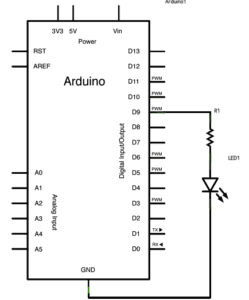
Circuit 1: Fade

components

1 * Arduino Uno

1 * USB A to B cable

1 * breadboard

1 * LED

1 * 220 ohm resistor

Jumper cables

Process and Problems

It worked…But what did it mean???

The process of building up the circuit went quite smooth until we were confused by the two wires connecting separately from the anode to the anode and from the cathode to the cathode. We did as what the instructing image told us but remained curious about the reason. By interpreting this image carefully and asking around, we got the answer that this was for connecting batteries.

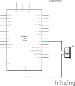
Circuit 2: toneMelody

components

1 * Arduino Uno

1 * USB A to B cable

1 * breadboard

1 * buzzer

Jumper cables

Process and Problems

We were happy to find that we did not even need to connect the pushbutton into the circuit. However, I was then confused by the question that whether I could directly connect the buzzer to the Arduino Uno with two wires. What was the point of first connecting to the anode of the breadboard then to the buzzer? At last, we found we actually only needed two wires directly connected between the Arduino Uno and the buzzer.

Circuit 3: Speed Game

components

1 * Arduino Uno

1 * USB A to B cable

1 * breadboard

1 * buzzer

2 * LEDs

2 * 220 ohm resistors

2 * 10K ohm resistors

2 * pushbuttons

Jumper cables

Process and Problems

An easy way to distinguish 10Ω & 220Ω?

When we were building the circuit, we had to use multimeters for several times to distinguish different resistors. It was just too cumbersome. Could there be a simpler way to distinguish them? Definitely. Just look at the colors (hope I am not the last one to know). The one with two orange strips is 220Ω, while the one with only one orange strip is 10Ω. Knowing this saved us much time testing the resistor repeatedly. 

Some thoughts on how to find out the reason for not-working circuit

Before the circuit could operate successfully, we tried hard to figure out the reasons for each failure. At first, it was because we mistook the resistors. Then, it was because we missed a wire to the Ground. For our last failure, it was just due to a broken LED. We had the mindset that the reason should be complex, thus, we tended to check our code and arrangement of electronics as soon as something went wrong. However, as we had learned, though basic these problems were, the states of the electronics and the completeness of the whole circuit should be the priority to check.

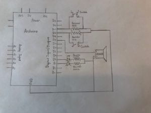
Circuit 4: Four-player Speed Game

Process and Problems

After finish Circuit 3, my partner and I teamed up with another group of two, trying to build a four-player speed game. Connecting two circuits for the two-player speed game, we moved all the wires for input and output to one Arduino Uno, and canceled the extra buzzer. 

Why Player 4 remained missing???

The circuit seemed to work well the first we tried. However, we soon recognized the problem that player 4 only had one output during the whole time, which was impossible. Too many wires made it extremely hard to figure out which represented player 4, so we checked by running a code for lightening up the LED separately. Finally, we found two of the four circuits had problems. Checking the connection and the electronics, we only managed to make one of them work. 

Why another LED went on???

With one of the four circuits not working, we decided to operate it as a three-player speed game (75% of the goal achieved). After a tense speed game, as you can see in the video, the LED supposed to connect to the winner gave no reaction. Instead, the opposite LED went on even though nobody had pressed the button. Excluding supernatural reasons, we took a guess that it might just because these two LEDs were connected into each other’s circuit. 

Answers to the questions

Question 1:

Reflect how you use technology in your daily life and on the circuits you just built. Use the text Physical Computing and your own observations to define interaction.

For me, technology can be divided into two parts. one is the complex theory of how to get things work, while the other part is the presentation of what it can help people to achieve. In my daily life, I seldom think about the hidden theory part, focusing what I can do with the help of technology. For instance, I create arts through apps in my phone and take tidy notes via my laptop. With the similar attitude, when I was building the circuits, I did not try to figure out answers to questions like what was the mechanics in separative electronics. Instead, I put those electronics together through rather simple connection in order to make them work together. In other words, I did not invent technology, I utilized and combined invented technology.

This leads to my definition of interaction. In my view, interaction is combing ideas and abilities from different sources to provide more possibilities. In the text Physical Computing, it writes that “Author and game programmer Chris Crawford has a great definition for it: interaction is ‘an iterative process of listening, thinking and speaking between two or more objects.’ (4)”. Specifically in the situation where human beings use technology, people are able to imagine more freely without worrying about details on how to make each part of their imagination come true. Human beings are responsible for putting present technology together to solidify their ideas. therefore, interaction promotes the combination of ideas and abilities, to create something new without inventing anything new.

Question 2:

If you have 100,000 LEDs of any brightness and color at your disposal, what would you make and where would you put it?

I would like to start a LED-themed coffee shop which opens 7/24. It has several separate rooms whose walls are covered by LEDs. The LEDs are able to imitate any level of daylight to provide a comforting working environment. This coffee shop is specially for those who need to keep awake to fight for deadlines or who are strict about the light level while working. Customers can modify the color and the brightness of the room to fit their needs. Since they could have access to all the LEDs in their room, they can decide what the atmosphere of the room is like. 

Interaction Lab-Recitation 1 (Serene Fan)

Circuit 1-Door Bell

Components:

1*Breadboard:  A base for connecting components

1*LM7805 Voltage Regulator:  To regulate and maintain a constant voltage level which is suitable for the circuit

1*Push-Button Switch: Able to connect the whole circuit when it is pressed

1*Buzzer: To output an audio signal

1*100 nF (0.1uF) Capacitor: To store electrical energy

1*12 volt power supply: To provide power source

1*Barrel Jack: An electrical connector for supplying direct current

Jumper Cables (Hook-up Wires): To connect components

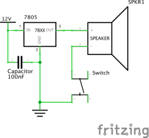
The Diagram
The Building Process and Problems We met

How to connect the switch???  

When we were connecting the switch, we found it difficult to distinguish which two feet to choose. We expected there should be different length of the feet so that we could identify the anode and the cathode, but all the four feet seemed the same. Out of ideas, we turned to Nick for help. He then told us the way of connecting the switch was to  know that foot A and D are always connected. Same with foot B and C. Therefore, only connecting either A or D to either B or C can be counted as successful connecting.

Where is the voltage regulator???

We first built the circuit without the voltage regulator, because we misinterpret the symbol for the voltage regulator as the power source. Since the circuit still worked well, we did not notice this mistake. However, Leon came by and pointed out that we should add the voltage regulator to the circuit in case the voltage level could be too high for it. Therefore, we corrected our circuit and it worked again. 

Circuit 2-Lamp

Components: 

1*Breadboard:  A base for connecting components

1*LM7805 Voltage Regulator:  To regulate and maintain a constant voltage level which is suitable for the circuit

1*Push-Button Switch: Able to connect the whole circuit when it is pressed

1* Arcade Button: Able to connect the whole circuit when it is pressed, but needed to be soldered

1*220 ohm Resistor: To reduce current flow

1*LED: Able to emit light when connected to the power source

1*100 nF (0.1uF) Capacitor: To store electrical energy

1*12 volt power supply: To provide power source

1*Barrel Jack: An electrical connector for supplying direct current

Jumper Cables (Hook-up Wires): To connect components

1*Multimeter: To measure voltage, current and resistance

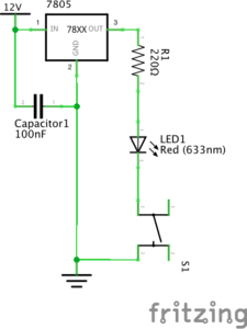
The Diagram:
The Building Process and Problems We met

Why the light was not on???

We built the circuit exactly as what the diagram told us, however, the LED just refused to emit light. We checked every connecting point without recognizing any problem. At last, we asked Nick about this situation. As he suggested, we used the multimeter to measure the resistance and surprisingly figured out that we connected the wrong resistor, which was only 10 Ω. We immediately altered the resistor and the light went on.

We replaced the switch!

After soldering the arcade button, we decided to replace the push-button switch. The process was quite simple. And we found that there was no need to take down the push-button switch while connecting the arcade button.

Circuit 3-Dimmable Lamp

Components

1*Breadboard:  A base for connecting components

1*LM7805 Voltage Regulator:  To regulate and maintain a constant voltage level which is suitable for the circuit

1*Push-Button Switch: Able to connect the whole circuit when it is pressed

1*220 ohm Resistor: To reduce current flow

1*10K ohm Variable Resistor (Potentiometer): To change the resistance in a close circuit

1*LED: Able to emit light when connected to the power source

1*100 nF (0.1uF) Capacitor: To store electrical energy

1*12 volt power supply: To provide power source

1*Barrel Jack: An electrical connector for supplying direct current

Jumper Cables (Hook-up Wires): To connect components

1*Multimeter: To measure voltage, current and resistance

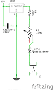
The Diagram
The Building Process and Problems We met

Why the light was not on again???

Again, we followed the diagram but found the light was not on in a close circuit. Based on experience, we checked the resistor and were sure it was the right one. What confused us was that the first time we pressed the button, the light was on perfectly. However, every time we pressed the button, the light became dimmer until it vanished completely. We were afraid that we might have burnt the light for some unknown reason, so we asked Marcella for help. She checked our circuit and told us we connected the variable resistor in a wrong way. 
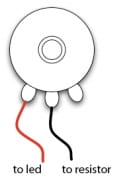
As the picture above shows, we then connected the left and the middle terminals into the circuits. It turned out that the circuit worked well and we did not burn the LED.

Reflection

The diagrams were simple enough to understand and the building process was quite easy. However, we still met problems. After the solutions were figured out, I reflected on why these problems have come up. One reason was that we did not read the instructions carefully enough to clearly know how to connect every components. Another reason was that we were not familiar with the breadboard, which made us panic easily every time there existed problems. For solutions, I found a helpful piece of reading in the instructions for this recitation called “Getting Started in Electronics”, through which I could access detailed basic knowledge of electronics. 

Answers to the questions

Question 1:

After reading The Art of Interactive Design, do you think that the circuits you built today include interactivity? Please explain your answer.

According to The Art of Interactive Design, there is no absolute answer to the question of whether an object is interactive. Instead, the degree of interactivity varies subjectively. Therefore, the circuits I built in the recitation can be regarded as interactive. As the author defines, interactivity happens when actors listen, think and speak, which can also be defined academically as input, process and output (5). In this case, one actor is the circuit while the other is the person who presses the button. During the process of interaction, the circuit listens (to the action of pressing the button), thinks (through processing the action), and speaks (by turning on the light or the speaker). Therefore, there did exist interaction.

Question 2:

How can Interaction Design and Physical Computing be used to create Interactive Art? You can reference Zack Lieberman’s video or any other artist that you know .

Interaction Design functions as a mediate for its objects to create Art, and Physical Computing can be used as a tool to achieve Interaction Design. In Zack Lieberman’s video, he launched three artistic practices, respectively called “Drawn”, “iq Font” and ” Eye-writer”, with his software skill. Through these practices, his softwares allow people to create Art and expresses with low barrier. That is how Interaction Design and Physical Computing can be combined to create Interactive Art.