Project Proposal – James Bai

Floating Keys

This project’s idea originated from our usage of the infrared distance sensor for the midterm project and me practicing the piano five hours ago. We wanted to create a piano-like object that when you put your hand above a sensor it plays a note, and there will be multiple sensors for multiple notes across this “keyboard”. Furthermore, there will be a game on the laptop screen (run by processing) for the player to follow along and play notes to famous pop melodies. The player must place their hand above each sensor according to the computer to win the game, and there will also be a mode to free play the notes. Research wise, we thought of games like Guitar Hero or Rock Band (Figure 1), where you had to play the instrument along with the notes, but we wanted to make it more fun and futuristic to put your hand above the notes instead of touching them. The game is meant for people who have little experience in piano, play the notes in a game-style to make it more enjoyable and less tedious. However, I think it will be fun for everyone – even those who have lots of experience on the piano.

Figure 1 (37 second mark):

Simple Gamebox

For the Simple Gamebox, we intended for a user to have a gaming experience (like an Xbox) on their computers using just a joystick and the enter button. However, we want the games and controls to be very simple and require less memory and Frames Per Second than Xbox games. The thinking and research process started off with the idea of just having a modified Space Invaders related game (Figure 2). However, we wanted the user to have more options, like Tic Tac Toe and many other games, being all at the control of a joystick. Our main inspiration was the Xbox App on Windows PCs where you could connect a controller and play. We believe the challenge we want to address is that many computers cannot process Xbox games and enjoy using the controller, therefore they resort to online flash games and others. We want to allow them to have a controller experience without the requirement of a computer that provides a high FPS in games.

Figure 2:

The Maze Race (With a 4D Audience Experience!)

For The Maze Race, the main components are two robots (or objects), controlled by keys on the keyboard. This is a two-player game, and both players can see the robot move in a 2D maze on the screen. All of this, however, will be in real life facing a different direction for the audience to watch; so there will be a 3D maze with two actual robots being controlled. Every time a button is pressed on the keyboard, the robot moves accordingly. Our two inspirations from this project proposal were the games Temple Run (Figure 3), and the movie The Maze Runner. We wanted to create a competitive environment that incorporates the core competencies of the movie and the game. We also wanted this to be interactive with the audience in that they can see who is winning in the diagram. The targetted audience for this project is just two players to challenge each other in a race and an actualy audience watching the game take place in a real model. We want the players and the audience to experience this game at the same time, doing different tasks.

Figure 3:

Recitation 7 – James Bai

In this recitation, we focused on creating functions and arrays.

Step 1: 

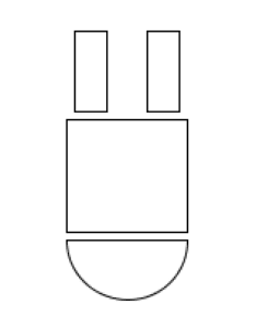
I created an upside-down Android shaped object in this step with a semicircle on the bottom, a square for the body and two rectangles for the legs. So it is like an Android thing falling.

The code for the buggy (with x and y values because I was testing out how it looked) is:

void buggy() {
arc(200,200,75,75,0,PI,CHORD);
rect(162,125,75,70);
rect(167,70,20,50);
rect(212,70,20,50);

And it looks like:
Step 2:

To allow it to fit in the for loop by having paramaters, I changed all the x and y values for the void buggy, added a strokeWeight(1); and stroke(c); and added the paramaters to the void parentheses so the code looked like:

void buggy(float x, float y, color c) {
strokeWeight(1);
stroke(c);
arc(x,y,75,75,0,PI,CHORD);
rect(x-38,y-75,75,70);
rect(x-33,x-130,20,50);
rect(x+12,x-130,20,50);
}

With that, I created the for loop which looked like:

for (int i=0;i<100;i++){
buggy(random(width),random(height),color(random(255),random(255),random(255)));
}}

When I put it inside void setup, it did not work and the screen was completely white with no figures on it.

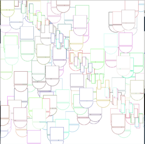
And I copied and pasted it onto void draw and my figure kept flashing across the screen in different directions. And this was fixed by adding noLoop(); to the end of void draw.

At this point it looked like this:
Step 3:

For this step, we had to create three arrays, store their data in setup, and display them in void draw.

I started off by creating the three universal arrays:

float[] xVal = new float[100];
float[] yVal = new float[100];
float[] cVal = new float[255];

This means that there will be a total of 100 random x and y values created for the x and y value arrays, and 255 random colors.

To store the values in setup I create two for loops (one for the x and y values and one for the color), I wrote the code:

for(int i=0; i<xVal.length; i++) {
xVal[i] = random(width);
yVal[i] = random(height);
}
for(int i=0; i<cVal.length; i++) {
cVal[i] = color(random(0,255),random(0,255),random(0,255));
}

This stores the values for x and y to have a random width and height 100 times (which is the xVal.length). xVal.length and yVal.length are pretty much the same thing (because they have 100 values).

For the last part of this step, I changed the for loop I had earlier for the buggy by switching 100 to xVal.length and inserted the stored parameters into the buggy so the void draw looks like:

void draw(){
background(255);
for (int i=0;i<100;i++){
buggy(xVal[i],yVal[i],cVal[i]);
}
noLoop();
}

This was when I came into my first error that showed:

After asking a learning assistant, I found out that at the top,

float[] cVal = new float[255]; is wrong.

It should be color[] cVal = new color[255]; instead.

And everything seems fine until I looked at the final product again and..

The legs are not connected with the body…., they are scattered in a diagonal line from the top left of the screen to the bottom right.

And I found out the code for the buggy was:

void buggy(float x, float y, color c) {
strokeWeight(1);
stroke(c);
arc(x,y,75,75,0,PI,CHORD);
rect(x-38,y-75,75,70);
rect(x-33,x-130,20,50);
rect(x+12,x-130,20,50);
}

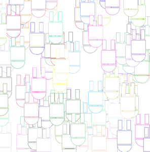
And…. for the last two rect();s, I put in x-130 instead of y-130.

After changing that, everything was back to normal as shown here:
As of now the code looks like (before I change it more):

float[] xVal = new float[100];
float[] yVal = new float[100];
color[] cVal = new color[255];
void setup(){
size(800,800);
for(int i=0; i<xVal.length; i++) {
xVal[i] = random(width);
yVal[i] = random(height);
}
for(int i=0; i<cVal.length; i++) {
cVal[i] = color(random(0,255),random(0,255),random(0,255));
}
}

void draw(){
background(255);
for (int i=0;i<100;i++){
buggy(xVal[i],yVal[i],cVal[i]);
}
noLoop();
}

void buggy(float x, float y, color c) {
strokeWeight(1);
stroke(c);
arc(x,y,75,75,0,PI,CHORD);
rect(x-38,y-75,75,70);
rect(x-33,y-130,20,50);
rect(x+12,y-130,20,50);
}

Step 4:

To animate it and create individual movement, I wanted to move the buggys from left to right at a small amount (between -1 and 1 x and y). So inside the for loop, I changed the code to:

buggy(xVal[i]+random(-1,1),yVal[i]+random(-1,1),cVal[i]);

Therefore having the x and y value increase or decrease by any number between -1 and 1.

Also for this to happen I would have to have it move around, so I took out noLoop();

Next, I created an integer of i to equal 0, to match all the i’s in the buggy an elsewhere. So it would be int i = 0;

After that, I created an if command (I had to make sure it was outside the for loop and not inside by asking a friend). And the if command incorporated the integer i = 0, and it said that if i was 0 or greater the buggy would move around.   I tried putting int i == 0, but it didn’t work so only i >= 0 worked.

So after everything, the whole code looked like:

float[] xVal = new float[100];
float[] yVal = new float[100];
color[] cVal = new color[255];
int i = 0;
void setup(){
size(800,800);
for(int i=0; i<xVal.length; i++) {
xVal[i] = random(width);
yVal[i] = random(height);
}
for(int i=0; i<cVal.length; i++) {
cVal[i] = color(random(0,255),random(0,255),random(0,255));
}
}

void draw(){
background(255);
if(i>=0){

for (int i=0;i<100;i++){
buggy(xVal[i]+random(-1,1),yVal[i]+random(-1,1),cVal[i]);
}
}
//noLoop();
}

void buggy(float x, float y, color c) {
strokeWeight(1);
stroke(c);
arc(x,y,75,75,0,PI,CHORD);
rect(x-38,y-75,75,70);
rect(x-33,y-130,20,50);
rect(x+12,y-130,20,50);
}

And here is a video of it:

Question 1:

So the for loop worked in void draw instead of void setup. I think this is because void setup only runs the code from top to bottom once, while void draw continuously runs it from top to bottom. Therefore void draw fits the for loop better because the for loop needs to keep drawing until a certain number, which is described after the first semicolon in the for loop function. For example in this function it was i<50, so the for loop had to run 50 times in total, and void setup cannot do that, only void draw can.

Question 2:

Arrays can store values that you can bring up later in coding. I think the benefit is that you can store all the values you think you need earlier on in the code so you don’t have to bring it up one by one later on using int = x. Another benefit could be to store a random array of numbers and use it later on in your code in a random number provider, being that those numbers are specific to the range you want.

Recitation 6 – James Bai

Processing Animation

Animating My Creation from the Last Recitation

Last recitation, I created the Mercedes Benz symbol using triangles and circles around the outside for rings.

To review it looks like:

So my idea for this recitation, in order to animate it, was to let it spin as the mouse got closer to the center of the circle.

So first I tried adding a pushMatrix();, where the code is shown here:

However, I kept getting an error that said pushMatrix() cannot be used more than 32 times. The teaching and learning assistants also suggested that I animate the project with colors instead since spinning the Mercedes symbol was quite complex, especially for that recitation.

So I added this line to my code:  , which resulted in this color for a background when my mouse moved halfway across the screen.

I wanted to add more animation to this so that it flickers constantly so I added this code:

The else if part is to reset the background to black, from the random RGB colors that flicker when the mouse moves further than x = 400.

Here is a video of the animation:

(Sorry my Adobe Premiere subscription expired so I can’t cut out the beginning and end for now)

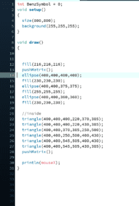
The whole code looked like:

int BenzSymbol = 0;
void setup()
{
size(800,800);
background(255,255,255);
}

void draw()
{

if(mouseX>400) {
background(random(255),random(255),random(255),random(5));}
else if(keyPressed == true) {
background(0);
}
fill(216,216,216);
ellipse(400,400,400,400);
fill(230,230,230);
ellipse(400,400,375,375);
fill(255,255,255);
ellipse(400,400,360,360);
fill(230,230,230);

//inside
triangle(400,400,400,220,370,385);
triangle(400,400,400,220,430,385);
triangle(400,400,370,385,250,500);
triangle(400,400,250,500,400,430);
triangle(400,400,545,505,400,430);
triangle(400,400,545,505,430,385);

println(mouseX);
}

Final Project Step 1 – James Bai

Preparatory Research and Analysis

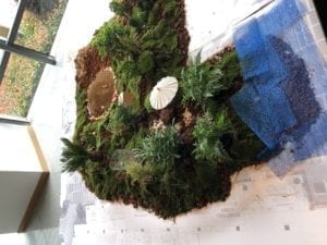
When I was at the Chronus exhibition, many of the designs and spacing reminded me of non-technological art exhibitions such as the “Goldenrod” exhibition downstairs (See Figure 1). The Chronus exhibition was similar in how the projects led to more different projects (you cannot just view and understand them all at the same time). For example, when you entered there was the machine with claw like black tubes that went towards you if you were close enough, and you had to go through a hallway to see the rest of the projects. And they all just provided an abstract feeling where you had to analyze a description or really take a deep look at the project to understand it’s use or message. An example was the wooden structure, that represented a reverse computer where the middle was being controlled by outside movements (See Figure 2). From afar it seems to be a nest or a cage, but after spending a few minutes and seeing how each outside part controlled the red strings inside gave me this idea of how it represented a reverse computer (reverse because the outside controls the inside). Similarly, in the art gallery downstairs there were two dioramas that made little to no sense when I first saw them, but after exploring the exhibition I found out that they were created by students and faculty to portray a campus displaying a coexistence between NYU Shanghai students and nature.

And this difference was what I found to be an essential component of interaction, one that I will focus on creating for the final. That is, I want the viewer to spend time analyzing my project and really testing it out to see how different uses of it will create different outcomes. 

For my 1st idea of my project, I wanted to create something where the user interacts with the computer and an Arduino project. I looked up games you could create with processing and I came across the “Duck hunt Banner” which was playable on the web browser.

Here is the link to play it: https://www.openprocessing.org/sketch/521767

However, I want to go further on my final project by creating a game that, of course, you can win or lose, but I would have an Arduino created robotic arm to turn to a thumbs down when you lost.

An example of an Arduino Robotic Arm can be seen here: https://create.arduino.cc/projecthub/msr048/robotic-arm-62c4c2

So vice versa, if you won it would turn into a thumbs up.

Although these are two ideas, I think it would be interesting to combine them into one single idea since we can use Processing to animate and Arduino to have physical interaction. I would of course also include a speaker or buzzer to signal a win or loss, and this project would have further added ons to create a stronger experience when won or lost.

For my 2nd Idea of my project I got an idea from these two projects:

Coke Can Piano: https://codeduino.com/projects/music/coke-can-piano/

Arduino Based MIDI Volume Pedal: https://codeduino.com/projects/music/arduino-based-midi-volume-pedal/

My idea is to create a sort of DJ booth using something abstract for the piano keys and having a custom created knob for the level of notes. The piano keys would something similar to Coke cans, like buttons.. or something cool enough like small circles with infrared sensors inside, that when you put your hand over it a certain sound plays. And the custom knob would be on the side of these to control the notes. More specifically, if I turned the knob it would play C3 instead of C4 on the same circle (with the infrared sensor). The second project describes the issues with volume control on an Arduino, and having the knob change the volume was one of my first ideas. Even though it does not have the features of a perfect DJ setup, I think it would be an interesting project.

For my 3rd Idea, it was a branch out idea from the second.

I was thinking of creating the same concept, with the circles and infrared sensors, except for drum beats. This, although is really similar, differs in the notes being played. Since drum beats do not have many sounds there would be less circles. And since drum beats are more repetitive it would be easier for the user to play around. I would use MP3 players or a buzzer for each individual drum sound.

Going back to the definition of interaction from these 3 projects, I think that they should all include some sort of mystery and randomness for the user. It of course much incorporate the project reacting from something the user did, such as putting his/her hand on top of the infrared sensor and it giving out different sounds. However, the project should also allow the user to test it out and analyze it to find out how to use it to maximum efficiency.

Appendix

Figure 1: (Diorama in “Goldenrod”)

Figure 2: (Video of Wooden Computing Machine

Video

Midterm Reflection – James Bai

“Halloween Stay Away Machine”

My previous research for the group project had not much of an impact on my midterm project since we had to create the midterm project, and the group one was just a proposal for a futuristic object. For our midterm project, the idea at the beginning was to create lights, that when close enough they turn red and when far enough they are green. We also planned to add fans to turn on faster when close and turn off when far. This idea seemed quite simple, and we found out during the user testing and feedback before the actual presentation. We got a lot of feedback to complicate our project and have it produce or evoke emotion, instead of its simplistic current state. This was really helpful, especially with suggestions of what it could do. We took the idea to create a surprise when the user got close enough, so we went with the scary clown.

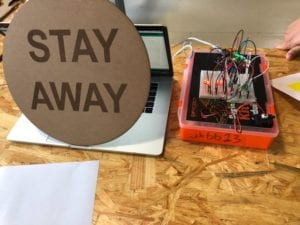
We wanted users to have a sort of rebellious decision to come closer to the “Stay Away Machine”, and once close enough they would be punished. We did this by adding a green light, which lured the user close enough. We even created a sign that said stay away (with digital fabrication), knowing that users would come close. For the clown that popped up, we wanted to use something not too gory, or something that would not produce a nightmare for the users. The core component of our project was using the infrared distance sensor. This addition allowed us to track distance, print it on the serial monitor, and have the clown turn up and the lights turn red when close enough to the machine. We wanted this project to be like the jack-in-the-box or sudden scare surprise, so we used distance to automate the clown popping up or going down. We really tried to think of a way for the clown to go up and down and not have to turn around with the servo, but we could not think of a way to produce that effect.

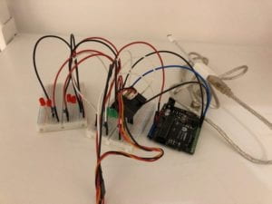
Here are pictures of just the lights:

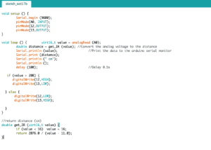
Here is the code for just the lights:

Thinking of the idea was not too hard, we combined our ideas and agreed off a project design for the midterm at a really fast pace. However, getting the code was quite time-consuming. Since we had to use conditionals to control the speaker, the servo, and the LED; we struggled with the code a bit. Especially since we spent 20 minutes trying to find what was wrong until an LA told us we were missing a curly bracket at the end of the conditional. This is essential, as we did not really double-check everything and the smallest mistake created such a hassle for us. On the day of the presentation, the machine was not working properly, as there seemed to be a delay for to clown to pop up once close enough to the machine. It was all working the day before with the same voltage and power connections, but it just stopped working the next day. Eric described that this should be a problem with power usage since the speaker requires quite a bit of power. This should have been the problem, so we should have added another 7.5V power adapter. Even though this already happened, we learned this lesson and will apply it to the future. We also tried incorporating a scary tune to the buzzer, but we couldn’t find the chords for one to google so I just tried putting in A-minor, C, E, A-minor, etc..

Here is the final version working:

IMG_3874

The goal of the “Halloween Stay Away Machine” is to create a clown that pops up and evokes a surprising emotion for the user. It interacts by having the clown appear when close enough, and the clown goes down when far away. We tried to use the risky behavior of people, to get close when it says to stay away, and create a surprise to sort of punish that riskiness. It is sort of like the scary movies when the character still goes downstairs, when everything seems wrong, and finds out there is paranormal activity down there. The audience did exactly that and kept walking up and trying out the project (although there was a delay problem on presentation day). We learned a lot from this project. From checking the smallest errors to using our creativity and creating a machine out of our ideas, it was a really interesting experience.