Isaac Schlager Recitation 4 Documentation (Eric Parren)

Recitation 4: Drawing Machines

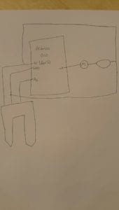
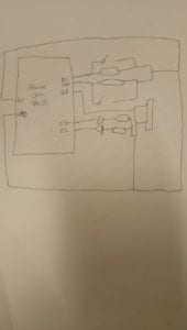
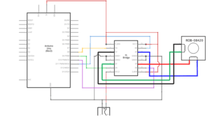
Below are lists of the materials used for each step of the recitation, as well as a diagram of the H-Bridge circuit and the code used for controlling the potentiometer and the stepper motor for each arduino.

Materials for Steps 1 and 2:

  • 1 * 42STH33-0404AC stepper motor
  • 1 * SN754410NE ic chip
  • 1 * power jack
  • 1 * 12 VDC power supply
  • 1 * Arduino kit and its contents

H-Bridge Circuit Diagram
Materials for Step 3 (with partner)

  • 2 * 42STH33-0404AC stepper motor
  • 2 * SN754410NE ic chip
  • 2 * power jack
  • 2 * 12 VDC power supply
  • 2 * Arduino kit and its contents
  • 2 * Laser-cut short arms
  • 2 * Laser-cut long arms
  • 1* Laser-cut motor holder
  • 2 * 3D printed motor coupling
  • 5 * Paper Fasteners
  • 1 * Pen that fits the laser-cut mechanisms
  • Paper

Steps 1-2 Controlling Potentiometers Code (for each partner)

/*

* MotorKnob

*

* A stepper motor follows the turns of a potentiometer

* (or other sensor) on analog input 0.

*

* http://www.arduino.cc/en/Reference/Stepper

* This example code is in the public domain.

*/

#include <Stepper.h>

// change this to the number of steps on your motor

#define STEPS 200

// create an instance of the stepper class, specifying

// the number of steps of the motor and the pins it’s

// attached to

Stepper stepper(STEPS, 8, 9, 10, 11);

// the previous reading from the analog input

int previous = 0;

void setup() {

 // set the speed of the motor to 30 RPMs

 stepper.setSpeed(30);

}

void loop() {

 // get the sensor value

 int val = map(analogRead(0), 0, 1023, 0, 200);

 // move a number of steps equal to the change in the

 // sensor reading

 stepper.step(val – previous);

 // remember the previous value of the sensor

 previous = val;

}

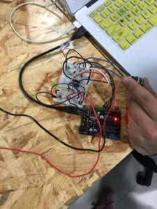
To begin this recitation, we were provided with an H-Bridge and were tasked with putting together a circuit with our Arduino where there was a stepper motor and an analog switch (potentiometer). We first had to individually build the circuit with the stepper motor and see if it would run properly. It took a while and I ran out of ground wires (black) and power wires (red) to use, but the circuit ended up running well.
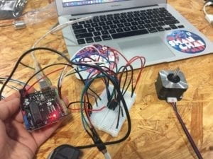
Our next step was to individually incorporate the potentiometer into the circuit, as well as add the potentiometer into the code. In my coding, I used a link that showed a template for a stepper and then included the potentiometer code in order to have an analog control the stepper. The difficulty here was using the map () function in my code to the point where I felt that I had sufficient control of the stepper motor.
Link to video below.

https://drive.google.com/open?id=1PwG2yqWbviiHsRsoziD2xR5-xNHA0fYD

Our last step for this recitation was to create a drawing machine that used 3D printed mechanical arms and screws provided to us. In order to do so, we had I had to attach my analog-controlled step motor to one arm, while my partner had to do the same. Then, where the arms come together, we used a pen that was sufficient enough to draw images on paper. We each would turn our potentiometers while the pen would make different movements and draw abstract images on paper. If we were to figure out better how the arms were calibrated, we could have probably drawn some basic images on paper.

Link to video below.

https://drive.google.com/open?id=1iapAnaxLHQOk_c2L6GehbvL4iT30_jLT

Recitation Questions

Question 1

I am figuring out that I am most interested in building analog connections with either stepper motors or servos in order to manipulate art and specific movements of objects. I enjoy creating arms that would move or lift things either for the purposes of drawing or satisfying other simple tasks. I am indifferent towards whether I am creating digital or analog connections. It is the fact that the creative process allows me to think of a problem that I would like to solve or or an object with a specific purpose that is entertaining and I can gradually work to create that project, from the prototype stages to constructing to the final product, and create something that can digitally manipulate the world around it which never ceases to amaze me. The use of actuators to push, grab, or reshape objects around them is something that I am particularly fascinated in.

Question 2

The most interesting art installation in Steven Wilson’s “Kinetics” chapter was the Gastarbyter created by London Fieldworks in collaboration with Dugal McKinnon. I find this installation to be most interesting because it allows its subjects to experience multiple senses while interacting with it. Subjects hear different audios, which correspond with different colored neon lights, which correspond with vibrations coming from a chair. Each actuator corresponds with touch and together portray what Wilson determines as a “mixed reality”. I think the artist selected his actuators based off of which senses he wanted people to feel when interacting with his art. It is clear that neon lights were used to provide different visual sensations and the speakers in the headphones were working with audio. The cylinders attached to the chair are interesting as well because they provide different vibrations to include touch as one of the senses experienced. Artists message was to show people how we tend to filter what we experience and all of these different sensations being experienced at once prevent the audience from filter certain things. I believe the circuits we created and actuators we used in this recitation, though are not as complex, provide people with a mixed reality as well. People have an idea of what drawing is, but the actuators (motors) we worked with provided them with a different sense of how to draw by making them use potentiometers to control the direction of the pen on a piece of paper. In the end, it was a meaningful experience for everyone involved, which is what Wilson believes interaction is all about.
Isaac Schlager Group Project Blog Post

My definition of “interaction” from a technological standpoint,  is “a relation where technology consistently and directly responds to human action”. There are a couple of important aspects of this definition  that I derived from the readings we have read, particularly Zack Lieberman’s piece. After reading Lieberman’s, “Open Mouth Effect” and seeing some of the projects he was working on, I noticed a common theme that resonated with me which was that all of the projects of his that I saw had consistent interaction and response to a specific set of human actions. For example, the interaction with the technology was not merely doing one thing, such as pressing a switch and waiting for something to happen. Each piece of technology would change its response patterns as the human interacting with it altered theirs. I believe that with today’s technology, we should have a more demanding definition of interaction and labeling things as “interactive technology” because the boundaries of what we can and cannot do are constantly being expanded.

Anti-Drawing Machine

https://www.creativeapplications.net/arduino-2/anti-drawing-machine-whimsical-and-imperfectly-characteristic-collaborator/

This project directly relates to my definition of interaction because there is a clear connection between a human drawing and a machine reacting to those drawings. In this project, a person begins drawing on a piece of paper. While they are drawing, sensors pick up the movements of their hands and pencil and react to it by moving the paper. This makes it more challenging for the artist to draw what they want. The purpose of this project was to exploit the idea of imperfections or “imperfect characteristics”. I would consider this to be what Zack Lieberman describes as interactive art that creates an “open mouth effect”. People using this technology for the first time would definitely be seen in awe. The basic ideas and intentions of this project are also clearly shown and it is obvious that the creators began with the basics of brainstorming ideas, as mentioned in Physical Computing, and progressed from there. In general, this project also represents how technology is influencing the way us humans view certain phenomena, by altering people’s drawing and providing them with a different perception of art than the “perfect lines” idealism that is ingrained in us since primary school.

Immersive Art Experience, “The Bomb”

https://www.vice.com/en_us/article/3kvwaw/an-experience-at-the-heart-of-nuclear-annihilation

Overall, this exhibit does not satisfy my definition of interaction. I believe that technology must directly respond as long as there is a human action to initiate things. For this show, I am sure there is someone who pushes multiple buttons and switches in order to start things, but from my standpoint, a majority of the audience is being ignored by the technology that is running the special effects, audio, and video. This project differs from the Anti-Drawing Machine project in that the Anti-Drawing technology automatically reacts whenever there is a person drawing. More importantly, there is a constant connection as long as someone initiates the action and there is mutual reciprocation between both parties as well. For example, in the Drawing Project, the paper is constantly being moved as the person draws and the person alters their drawing in reaction to the paper. For this other project called, “The Bomb”, even though members of the audience may experience Lieberman’s, “Open Mouth Effect”, they are not awed in the same way. In Lieberman’s car/ driver project there is a consistent connection between driver and the car being projected on the screen, but in the 4D art show the audience members may be reacting to the technology, but they are also essentially being completely ignored.

Our product, the “Super Box Boo 3000” not only satisfies my definition of interaction but also reflects many of the thoughts and ideals of the readings from the previous three weeks. This state-of-the-art 22nd century technology, for under 1 bitcoin, allows you to to make your very own style of shoes! For this product, all you need to do is upload a make and model of a shoe with any pre-selected or personally-created design to its database and then allow the box to calibrate your foot size and you’ll have all the shoes you want without ever having to leave your home! This technology satisfies my definition of interaction in that the audience can communicate with it in multiple ways. First, the user can create and upload a design to the Super Box Boo and then put their foot in. As soon as this happens, the box works its magic and 3d prints an entire shoe onto your foot for a fraction of the time that it would take for you to go to the store. I know for sure that this would provide customers with Lieberman’s “Open Mouth Effect”, in addition to it representing the category of interfaces and databases that directly shape human life as we know it. With this shoe-making technology, we can revolutionize how we shop. We already have been through one societal transformation with since the advent of online shopping, but this technology would most surely usher in a new wave of change that would shape human interactions with their environment for the future. Pete Manovich would most surely write about the Super Box Boo 3000 if he were alive to witness its greatness.

Isaac Schlager Recitation 3 Documentation (Eric Parren)

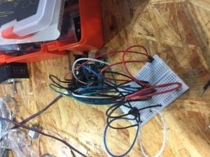
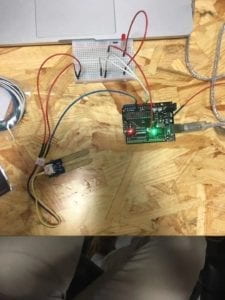
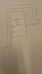
For our circuit we used a moisture sensor not only because of how cool it was, but also due to its practicality when measuring moisture levels in soil. The components of our circuit were an Arduino, an LED, a 100 ohm resistor, and a moisture sensor. We later attempted to add more actuators into our circuit with a buzzer and a motor. Our circuit had a 5v power input running to our resistor and LED and through to our moisture sensor. We also had an A0 input running towards our moisture sensor. Both the current coming from the resistor and LED, as well as the current from the moisture sensor traveled to ground as well.

While building the circuit with the LED, we didn’t encounter any problems with coding or constructing the circuit. It was only when we tried adding the buzzer that we ran into issues. The buzzer was not making any noise, so we looked at our code’s “if” statements for the buzzer and they were not written correctly. Once we fixed these airs we tried the circuit once more, but the buzzer still wouldn’t sound. We tried removing or replacing the resistor and buzzer but to no avail. We even tried increasing and reducing the range of the buzzer in our code. Despite this, we realized then that it wasn’t the construction our circuit that was wrong but that it was just infeasible to have that little power to light the LED and power the speaker at the same time, but to increase our power could mean frying the circuit. To solve this problem in the future we could probably use a transistor.

That being said, we decided to continue tinkering with our circuit and replaced the LED with a motor that had a fan attached to it. This ended up working and the fan’s rotation speed would increase as the moisture level on the sensor increased.

Question 1

What did you intend to assemble in the recitation exercise? If your sensor/actuator combination were to be used for pragmatic purposes, who would use it, why would they use it, and how could it be used?

In the recitation exercise we assembled a circuit that was connected to a moisture sensor and an LED light and speaker, but we realized that due to the amount of voltage we had, the circuit worked better with only the LED light connected to a 100 ohm resistor. I believe that our sensor/ actuator combination could be used for a multitude of practical purposes because there are many reasons why we may want to measure moisture. The first that comes to mind is measuring the moisture level in soil, so we can determine whether its worthy for plants, flowers, fruits, and vegetables. The more visible the light, the more moisture that is in the soil, which makes it more able to develop plant life. The sensor could also be used with soil to determine the amount of water being used to water plants and crops and whether it is enough or too much. Therefore, the sensor could be used to eliminate water waste as well. I can see farmers and agro-scientists using putting moisture sensors in dirt and soil to measure this very thing.

Question 2

Code is often compared to following a recipe or tutorial.  Why do you think that is?

I think of code as a recipe or tutorial because if you follow the steps to coding exactly then the results should pay off and you should be able to achieve what you want from whatever directions you follow. The same goes for a recipe or a tutorial because the only way to not mess things up and cause problems is to follow all the steps. A computer is not smart enough to sense whenever you make a mistake, which is why it is important to make sure you take your time and review your work. Code almost always delivers exactly what it asks from you, as do tutorials and recipes.

Question 3

In Language of New Media, Manovich describes the influence of computers on new media. In what ways do you believe the computer influences our human behaviors?

Through interfaces and databases on the worldwide web, computers have been providing us with a virtual universe and access to a multitude of free information. This can be shaped by our opinions, cultures, and other influences. Computers provide us access to the web which leads more people to publish free information and open source things. Computers have also influenced us to communicate in different ways with email and instant messaging. We no longer tend to send letters anymore and we are much more willing to use messaging services on the internet or apps to trade conversation with one another.

Isaac Schlager Recitation 2 Documentation (Eric Parren)

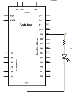
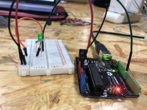
Circuit 1 Schematic, Photo, and Demonstration

The circuit’s purpose was to have a fading light come from an LED. This involved using the Arduino, an LED, and a 10k ohm resistor. To make this circuit work productively, we used the “Fading” example for code and then had a power source connected to D9 input. From there we used a breadboard and had the power cable going from the Arduino to a 10k ohm resistor and then running through an LED lights before returning to ground in the Arduino. Once we uploaded the code to our arduino, the fading of the LED worked perfectly and we has no issues. This made us both eager to tackle the next circuit and see if we can use other Arduino programs with lights successfully.

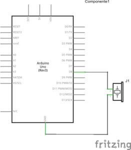
Circuit 2 Schematic, Photo, and Demonstration

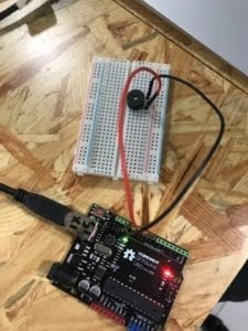
This next circuit’s purpose was to play a melody through a buzzer/ speaker. Our power source came from input D8 on the Arduino and ran into a buzzer/ speaker. From there, the circuit was connected back to ground on the Arduino. To run our code we went to the toneMelody example in the digital section and uploaded it to our Arduino. From there we were able to hear the melody being played and were lucky that we ran did not run into any issues with this circuit as well.

Circuit 3 Schematic, Photo, and Demonstration

In the 3rd and final circuit, we were tasked with creating a game in which two people could see who could tap a button faster within a given number of taps. If completed correctly, the Arduino program was to let us know when to begin and whoever was the winner had an LED light that was to light up if they won.To begin the circuit, we had a 5 volt input as our power source. We also had one input each from D10 and D11 that each connected to its own set of one switch and 220 ohm resistor before going to ground. We also had two inputs from D3~ and D2 that each ran through its own set of one LED light and a 10k ohm resistor before running back to ground as well. The D8 input had a wire that ran from the input to the speaker and from the speaker back to ground. We also had a code that was given to us on the projector that we were to copy and paste into a new Arduino file. With this uploaded, we were able to go to the serial monitor, where words that appeared on the screen would count us down to mashing the buttons. Initially, we forgot to look at the serial monitor when testing our circuit so we looked through each connection an extra time to made sure we were building it correctly. Once we figured this out, we began running the code and the entire circuit and game worked perfectly. We realized that we should always run our code first to see if it works before taking apart the circuit again.

The text “Physical Computing” really put into context for me how I interact with technology on a daily basis. I can now look at things, such as scanning my identification card while I’m entering school and know that those machines are in a digital space. The reading also narrowed down my view of what a computer and computing is, mostly because beforehand I also had the idea that computers looked like a screen, keyboard, and mouse. Now that I know that different methods of transduction and how things are more complicated than simply digital/ analog, input/ output I can see that the order in which things are processed, whether they are parallel or serial matter as well. One thing I found fascinating and that I will definitely keep in mind while I am creating projects in this class is the advice that was given when it came to brainstorming ideas. Despite all the complexities behind programming and making circuits and/ or microcomputers, it is important to look at you idea through its very basic connection and to not overanalyze or try to perfect what you have at first. This is something I have always been prone to do, especially being a social science major and writing tons of papers. I realize that I have to start basic and work my way up. Higher levels of abstraction can actually be a distraction when you begin working on a project because you do not want your ideas to become convoluted. I define interaction as communication between objects, whether they be living or not. I think that many of the parts of a circuit are interactions, just like I think moving an analog stick is an interaction. Circuits and computers are created by a team of things and when one thing goes wrong or has trouble, the entire thing is in jeopardy.

Question 2:

To be honest, I can assume all I want that 100,000 LEDs could lead to a very bright, visible light, but depending on how high in the sky I want them and the weather, they could be difficult to see. Initially, I thought of how practical this light would be at an airport or a shoreline to prevent crashes, but personally I would want to put all of the lights in the sky where they could light up different positive messages to the people below. I would want to put them on some sort of balloon or another device in the air and have they blink in different languages. Then again, I would know exactly what is powering them so I feel like that would inhibit my power sources for this project. If need be, I could make this project stationary as well as place it somewhere where people are in need and try to cheer them up with some sort of light show.

Isaac Schlager Week 1 Recitation (Professor Eric Parren)


Recitation 1
Circuit 1: Doorbell

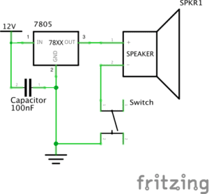
This circuit consisted of multiple elements, starting with a 12 volt power source at the beginning. Without this component, the circuit would have no power. The next component is a voltage regulator and its job is to maintain a consistent voltage level. There is also a capacitor that decreases the power level. The charges coming out of the capacitor and the second output of the regulator both get grounded, while the charge coming out of the third outlet goes directly to a speaker that makes noise and a switch that allows you to control whether noise comes out of the speaker or not. The purpose of this circuit is to emit noise out of a speaker. During the process of building the speaker we ran into a number of challenges that centered around our voltage capacitors being inefficient. We had to exchange three capacitors until our circuit was working properly.

Circuit 2: Lamp

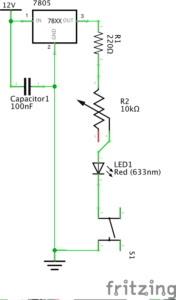
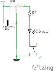
Our second circuit and its purpose was to light a small LED light. It began with a 12 volt power source that entered into a voltage regulator that maintained a distinct voltage level, as well as a capacitor that lessened the power in the circuit.The charges coming from the capacitor and the second outlet of the regulator both get grounded, while the outward charge from the regulator travels through a resistor. This resistor does exactly what it is entitled and resists the current coming through it. Then the charge travels through the LED light that is supposed to light up and then goes through a switch that allows you to control the light manually.

Circuit 3: Dimmable Lamp

The third circuit we were required to built had to light up another LED light, but had to have the ability to turn a knob and dim the light. It began with a 12 volt power source that entered into a voltage regulator that maintained a distinct voltage level, as well as a capacitor that lessened the power in the circuit.The charges coming from the capacitor and the second outlet of the regulator both get grounded, while the outward charge from the regulator travels through a resistor. This resistor does exactly what it is entitled and resists the current coming through it. The charge then goes through a variable resistor that allows you to manually change the amount of resistance to the current before it enters the LED light and a switch.

Question 1: In a way, our circuits include interactivity because the different components in them communicate with one another. I believe they do this through the energy/ charge itself traveling through the circuit. It seems as though each component decides to either alter the charge or is altered by the charge before it is grounded. I also think the circuits are interactive in that they all have switches that we can interact with.

Question 2: I think that both Interactive Design and Physical Computing can be used to create Interactive Art in that the technology used can involve an audience. One of the examples that Zack Lieberman mentions is the “open mouth phenomenon”, where he feels that it is the pathway to someone’s heart. This can be influenced by Interactive Art that is created from Interactive Design and Physical Computing, an example being the car/ driver project that Lieberman works on. These projects involve a lot of research behind them in order to be constructed and many people do not realize that.