Consuming Life- Isabel Brack- Inmi

Midterm Project: Consuming Life by Isabel Brack and Christina Bowllan

Context and Significance

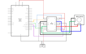
We first met to discuss or project concept the week before the testing day for recitation, that day we accumulated our own personal research and brainstormed project ideas. I presented the two main concepts we had discussed either an interactive game involving memory or whack-a-mole style games and in far contrast interactive art pieces mostly sourced from social art exhibits focusing around a comment on society like surveillance. I looked at probably 50+ examples of Arduino art to see different media mixing that artists used including looking at Arduino’s art page and many Arduino art Youtube videos like this. Although many projects were not the social statement we wanted to make, they gave us ideas on how to mix Arduino and art. The most inspirational art installation I found, personally, was a European installation of many plastic bags that would inflate and deflate based on a person’s movement, representing a creature’s movement and breath called “One Hundred and Eight.” This project had multifaceted interactions, including the physical interaction of the audience and the piece responding to each other’s movements, input, processing, and output. It also included an important interaction component for art pieces, an engagement with art where the audience engages with the art as a conceptual piece, interpreting its significance and meaning. I also took influence from my group project as we focused on a more practical, problem solving device, I wanted to expand my project’s conception to focus on an experience and interaction for the audience rather than just the object by itself. Our group project originally focused on the object itself and its components, sensors, and problem solving, rather than the larger goal of the experience our smart kitchen and alfa watch were creating. That project focused on a basic definition of interaction to only include the person and the machine/device. It had straight forward sensory inputs, processing, and then straight forward outputs of food/cooking the food. For me, art and a greater message seemed like a good way to create an overall experience that involved many aspects to the interaction. “Consuming  Life” as an art project involved the simple interaction of pressing a few buttons and observing their effects on the human system including lungs and heart, but the interaction also included an aspect of thinking and interpretation of the art, which I consider to be a vital piece of the interaction.  This is similar too the interactive art exhibit we visited this weekend. The audience needed to consider the physical interaction of the art piece and its greater meaning in the context of society and human life, which was part of the intended interaction and experience. With “Consuming Life,” the interaction initiated when the audience began thinking about how to interact with the piece, touching different elements, and the main interactions began when the audience touched the price tag and the “try me” button which represented the first steps of consumption. Our idea of interaction included interpreting and understanding of the entire piece even after the audience was done pressing each button. For the games we originally considered making, I found examples like a light memory game and wack-a-mole, personally after seeing these examples I preferred the art choice both because of the creativity and message that accompanies interactive art, and the fact that many of these games had been created many times and already had complete sample code. A personal goal of mine was to write the code basically from scratch to learn how to really use Arduino. So although throughout the project I looked at many sample codes to see different strategies and codes which would move DC motors and blink the lights in the fashion we wanted, most of the code I wrote without copying from any one source. The code was still influenced by many readings and other codes I read through regarding Bullion statements specifically, pullup resistors, and toggle. The circuit was also mostly based on the DC motor circuit we built in class with an H-bridge only adding a button and three red LEDS with their own button(see code at bottom of blog post).

Conception and Design
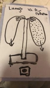
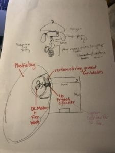
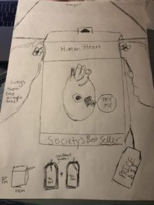
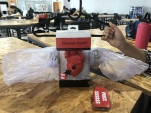
preliminary sketch of first idea. Air pollution lung model.sketch phase 2. entire organ system on hangerFinal sketch including price tag and try me buttons

           Sketch 1                                     Sketch 2                                      Sketch 3

Our first idea for this art project was a lung model showing the effects of air pollution on the human lungs (sketch 1). Our original fully realized design for “Consuming Life” was an entire human organ system that used working lungs, a blinking heart, and light up organs like the stomach, all created from plastic waste(sketch 2). We were going to articulate our message of consumption taking over human life and action, through the waste products consumption created. We used 2D laser cutting for the box to hide the Arduino and breadboard and 3D printing to create the heart and some mechanical pieces like hooks to hold the box on the hanger, and two cylinders that fit into the holes of the 2D laser cut box to support the two DC motor fans, which controlled the lungs. The heart we sourced from an open source anatomical model and modified it to have a whole through it for the button and wiring, and the mechanical pieces we printed we designed ourselves with aid from Linda and Andy (Image 1). The 2D box we also designed ourselves. Besides the 2 and 3D materials we used recycling to make the lungs, price tag, and product box for the heart, which we chose as it fit our theme of consumption and the control it has on humans and the waste it creates. The box we used for the heart, actually used to be a tox product container, so we only made a few alterations to strengthen the structural integrity and cut holes for the wiring and “try me” button. We thought about many different buttons and sensors, but we ultimately choose the arcade buttons because we could integrate their use while connecting it to the meaning. We could articulate through the price tag button that the beginning of the consumption process, looking at the price tag case the human to rely and be fueled by consumption. We could not convey that same message with other sensors like ultrasonic or infrared, which would have been more interactive. Regarding our expected outcome of the audience interacting with our creation, the user testing session was extremely helpful to determine what was unclear about our how to us it, specifically making the buttons more understandable and connected to the concept, consumerism engulfing and consuming humans’ lives, controlling every aspect of their existence, demonstrated most fundamentally by the toy and consumption of it controlling the human’s lungs and heart. During the testing session, we observed and were told that they knew to press the button because they were familiar with buttons, not because their intuition was to touch the button. As a result, we altered our connection between the inputs and the rest of our art piece. We added a second button that was more intuitive made with cardboard, tinfoil, and two wires to create a price tag button that with minimal pressure will turn the lungs on. We also transformed the button inside the heart into a “try me” button like the ones often seen on kids toys to give the button purpose and reason. After user testing, I again tried a bunch of sensor out including a piezo disk, pressure pad, arcade button, and finally settled for our own price tag button (Video 1) because conceptually it fit our theme and intended interaction the best. 
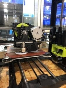
3D printing of the hooks and different parts to hold up the boxImage 1

Image 1: 3D printing of the different parts like hooks, washers, and cylinders to hold the fans in place and hang the box on the hanger.

paper prototype

Image 2

Image 2: The paper prototype that is the same detentions of our final 2D laser cut box.

Video 1: The construction and testing of the price tag button with sample code on a digital serial monitor.

Fabrication and Production

The design process, a paper prototype (Image 2), user testing prototype(video 2), and final art piece( video 3&4) all went through drastic changes from idea conception to the final product. Our first design was just a set of lungs that was controlled by a button to show the effect of air pollution on the human system, it acted more like a model than a piece of art. As we continued to create our prototype and discuss with the class our ideas, we learned that something hanging and eye level would be more effective in giving our project a human form, like the art exhibit we looked at commenting on surveillance, using belts to represent humans. Our instructor suggest using a hanger to demonstrate the human silhouette while keeping in as a more abstract art piece. Which we eventually suspended our project from a chair in the user testing and then from a string in the final presentation. This perspective gave it an art and human quality that was distinctive compared to sitting on a table which would hit it more of a model feel. We created a completely working project for the user testing, and from the participants we learned we needed to strengthen the message and purpose of our piece, specifically making our statement about consumerism more clear, and from a consultation with Marcela, she suggested we turn the heart into a physical product to represent consumerism. After the sessions, we took the entire project apart and created a new button, by making the price tag. We also turned the heart into a product by packaging it and adding a try me button and lights to eliminate the packaging. During the test session we got feedback mostly around the concept being confusing to understand as the lungs worked but much of the project was taped together and a lot of the mechanics of the box and hanging mechanism were exposed and confusing(Image 2). Based on this feedback we hid the mechanics and 2D laser cut box behind the toy heart box. We also eliminated the temporary adhesives like we initially planned to and glued the 2D box, the heart, and the toy heart box to each other to make the look more finalized, as you can see comparing image 2, the user tester version  to image 3, the final project. Our greatest setback was the morning of the user testing, while Christina and I set up the project to test it before we started, some of the wires in the box came undone without our knowledge (as the box covered all the arduino and wires). As a result of the loose wires, when we powered up the 12 V power source my Arduino board got fried. After noticing this we rewired the entire circuit to a new Arduino and checked the wires, with the help of Marcela. After the board was rewired and the connections were double checked, along with replacing the H-bridge, the project function how it was supposed to, but we had to disconnect the LEDs for the user testing because there was not enough time to rewire and check them before it began. The greatest changes in our project came after our class discussion of projects and after the user testing. Both times we altered the concept and the design of the project entirely. As a result our concept and project improved greatly from the design phase to the final project. While Christina focused on 3D printing and the physical construction of the lungs, I focused on the 2D laser cutting design, the code, and the circuit. And together we designed the piece conceptually and assembled the piece together. One other issue I ran into with the code for this project was I used two different bullion statements to control each button and its corresponding function, but in Arduino, the code is used sequentially so only one button could be pressed at a time, which could be confusing for the audience, in hindsight maybe two Arduino boards each controlling one function would have helped the interaction. For the code and circuit, although I wrote and made my own I took inspiration from DC motor circuit and code ,DC motors controlled by potentiometers, and two way DC motor  (our final code is pasted at the bottom of the blog post). Although in reality the circuit and code to inspiration from each combine into a new different code that included two bullion statements, input_pullup functions, and toggle which I learned in external research about how to use buttons to control different loads.

Video 2: The working prototype for the user testing session.

Video 3

Video 4

Video 3&4: The working Final Project breathing (3) and lights (4).
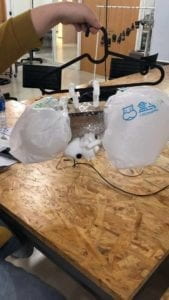
User testing version covered in tape

Image 2: User testing prototype

Final Project

Image 3: Final product “Consuming Life”

Conclusion

Goals

Our Arduino and circuit art piece, “Consuming Life” aligned with my abstract understanding of integration. The project had physical interaction between two actors, the audience was required to press a button as an input, processing and output occured on the form of breathing or red blinking lights, and the audience was also required to think about the experience, interpreting the art and meaning. The final aspect of our interaction is what I believe is the most significant. But, our project in some ways can lend itself more to a reactionary project, having the audience press some buttons and then observe the results rather than continue to physically interact with it. In reality, the audience had a difficult time thinking past the physical object and only after a few  students and instructors explained the concept did all the student understand the greater meaning and greater interaction. The interaction that took place between the project and the audience was similar to our expectations, they pressed the buttons and touched the lungs while they inflated to feel the breaths in and out. Some of the audience seemed to contemplate and engage with the project more than others as they closely observed the different details to the piece including our labels and the movements and connection between the price tag and the directions. If we had more time, I would have liked to have more aspects to the toy heart, like a heartbeat along with the red blinking to make the toy “try me” button more realistic. My main accomplishment and take away from this project was learning how to create my own code on Arduino based on learning the basic skills of bullion statements, blinking LEDs, and reversing motors. Also, I learned how to research many different codes, projects, and circuits, interpret them, and take inspiration to use on my own projects. In addition, I  think we fine tuned our creative process learning to value all of the resources the IMA program has in the fabrication lab and with the professors and fellows. I learned a lot about the process of these interactive projects, prototyping in paper and cardboard then creating a working version and trouble-shooting and debugging code, and the physical mechanics of the process. We especially had setbacks and learning moments while trying to get the lungs to breath noticeably. First we tried the fans in our arduino kits with plastic shopping bags, but the fans were not powerful enough and the bags were not as air tight and thick. Later, we settled on thing trash bags and super glue to ensure a tight fit, and thick plastic fans to increase the power of the fans. Once the lungs were air tight, I could better control the air movement and reverse the motors to create and inhale effect, making a more noticeable and realistic lung movement. In making this project there were two components that gave us, the creators, and the audience distinct value. First, discussing the social concern of consumption and the role consuming plays in every human’s life along with the control it exerts over our very existence. And, as creators of the project the district value I found was following a project through from the brainstorming and design, to testing, reworking, trouble shooting, and finalizing. As a process it was the definition of experiential learning, teaching yourself to trouble shoot multiple aspects like coding, circuits, and the physical mechanics of the project. I especially remember all the  trials and tribulations we faced to get the lungs air tight so that the motor could control both the exhale and inhale. Once we used the super glue and got the lungs to actually resemble human breath patterns, it felt like a real accomplishment, no matter how small a step it actually was, especially because we used trial and error for an hour or two to get our desired result. Between each design step we reworked our idea almost completely, to find the best final product we could based on our current skill level and time limit. From start to finish the project transformed resembling three conceptually and mechanically different designs each time. The process eventually lead us to our final result of “Consuming Life.”

Broader Conclusion

We created this project with a larger theme and goal in mind, not just the demonstration of lungs inhaling and exhaling and a toy turning on. Our goal was to make the audience think about humans’ relationship with consumption and plastic in their everyday life and possibly their own life. The initial consideration of a product’s price or function (the “try me”button) constitutes the first step of consumption, which in the modern era in inseparable from human life. As it is practically impossible to be self sufficient today, everyone is dependent on purchasing necessities, whether it be food and water or a toy anatomical heart. However, most of society does not think about their relationship with consumption and the environmental and societal effects it has let alone thinking of them self as a constant consumer. “Consuming Life” aims to demonstrate the inseparable bond between consumption and human life, suggesting a dependence on consumption to breathe and live. The greater meaning, experience, and interpretation, to me, is what I consider the “so what factor” to our project. Regarding the process of creating the process, this experience was helpful in improving my design process and execution, seeing the project through from research, brainstorming, sketching, designing, prototyping, building, testing, reworking, and finalizing.

Code:

int motor1pin = 6;
int motor2pin = 7;
// h bridge pin
int ButtonState = false;
int ButtonState2 = false;
int Button = 2;
int Button2= 4;
int red1= 8;
int red2= 9;
int red3= 10;
boolean toggle = true;
void setup() {

pinMode(motor1pin, OUTPUT);
pinMode (motor2pin, OUTPUT);
pinMode(red1, OUTPUT);
pinMode(red2, OUTPUT);
pinMode(red3, OUTPUT);

pinMode(Button, INPUT_PULLUP);
pinMode(Button2, INPUT_PULLUP);

}

void loop() {

int ButtonState = digitalRead(Button);
if (ButtonState == LOW)
{
if(toggle)
{
digitalWrite(motor1pin, HIGH); // motor turns on
digitalWrite(motor2pin, LOW);
delay (4000);
digitalWrite(motor1pin, LOW); // motor turns on
digitalWrite(motor2pin, LOW);
delay (100);
digitalWrite(motor1pin, LOW);
digitalWrite(motor2pin, HIGH);
delay (3000);
digitalWrite(motor1pin, HIGH);
digitalWrite(motor2pin, LOW);// motor and Redled turn off after 3 seconds after blinking finishes
delay (4000);
toggle = !toggle;
digitalWrite(motor1pin, LOW); // motor turns on
digitalWrite(motor2pin, LOW);
delay (100);
digitalWrite(motor1pin, LOW);
digitalWrite(motor2pin, HIGH);
delay (3000);
digitalWrite(motor1pin, HIGH);
digitalWrite(motor2pin, LOW);// motor and Redled turn off after 3 seconds after blinking finishes

delay (4000);
digitalWrite(motor1pin, LOW); // motor turns on
digitalWrite(motor2pin, LOW);
delay (3000);
digitalWrite(motor1pin, LOW);
digitalWrite(motor2pin, HIGH);
// motor and Redled turn off after 3 seconds after blinking finishes
delay (4000);
digitalWrite(motor1pin, LOW);
digitalWrite(motor2pin, LOW);
delay (13000);
}
else
{
digitalWrite(motor1pin, LOW);
digitalWrite(motor2pin, LOW);/// motor turns off
toggle = !toggle;
}

}
int ButtonState2 = digitalRead(Button2);
if (ButtonState2 == LOW)
{
if(toggle)
{
digitalWrite(red1, HIGH); // turn the LED on (HIGH is the voltage level)
digitalWrite(red2, HIGH);
digitalWrite(red3, HIGH);
delay(1000); // wait for a second
digitalWrite(red1, LOW); // turn the LED off by making the voltage LOW
digitalWrite(red2, LOW);
digitalWrite(red3, LOW);
delay(1000);
digitalWrite(red1, HIGH); // turn the LED on (HIGH is the voltage level)
digitalWrite(red2, HIGH);
digitalWrite(red3, HIGH);
delay(1000); // wait for a second
digitalWrite(red1, LOW); // turn the LED off by making the voltage LOW
digitalWrite(red2, LOW);
digitalWrite(red3, LOW);
delay(1000);
digitalWrite(red1, HIGH); // turn the LED on (HIGH is the voltage level)
digitalWrite(red2, HIGH);
digitalWrite(red3, HIGH);
delay(1000); // wait for a second
digitalWrite(red1, LOW); // turn the LED off by making the voltage LOW
digitalWrite(red2, LOW);
digitalWrite(red3, LOW);
delay(1000);
digitalWrite(red1, HIGH); // turn the LED on (HIGH is the voltage level)
digitalWrite(red2, HIGH);
digitalWrite(red3, HIGH);
delay(1000); // wait for a second
digitalWrite(red1, LOW); // turn the LED off by making the voltage LOW
digitalWrite(red2, LOW);
digitalWrite(red3, LOW);
toggle = !toggle;

}
else
{
digitalWrite(red1, LOW);
digitalWrite(red2, LOW);/// motor turns off
digitalWrite(red3, LOW);
toggle = !toggle;
}

}
}
Recitation 4: Drawing Machine by Isabel Brack

Overview:

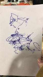
For this recitation we build a drawing machine, combining two stepper motor circuits, my partner and I each made in the first step and assembled the drawing machine with various fasteners and 3D printed parts. Our artwork resulted in picture following.

Art from drawing machine

Step 1:

Schematic for H-bridge stepper motor circuit

First, my partner and I individually built the first circuit, following the circuit diagram. Although I triple checked the wiring of the circuit my motor would not turn on when I uploaded the code. After asking a professor for help, he also double checked the wiring and found no problems, so we replaced each main part until the circuit worked. The H-bridge had been bent from the last use and would not connect to the breadboard properly, after the H-bridge was exchanged the circuit worked successfully. We used the sample code from arduino,stepper_oneRevolution. Below is the working stepper motor after the replacement of the h-bridge.

Step 2:

Step two required trial and error adding a potentiometer to the circuit was easy, connecting the middle pin to A0 and the other two pins to power and ground. Incorporating the mapping code was a bit more difficult. We used the code MotorKnob and altered it to include mapping the potentiometer to the motor using syntax: int izzy = map(val, 0, 1023, 0, 200);. We also changed the variables to be consistent with their new labels in this case “izzy” and “amy” and changed the #define STEP to #define STEP 200 to account for the steppers 200 steps. After the changes to the code were made the potentiometer successfully controlled stepper motor.

Step 3:

Putting together the machine itself was straight forward, fastening the different components together with paper fasteners. We had difficulty getting the pen close enough to paper to draw, and we eventually propped up a piece of paper on a notebook to get it to the correct height. After adjusting the height we also had to weigh the paper down so it doesn’t move with the pen (as it did on our first try). The potentiometer controls were a bit jumpy and not smooth for the most part while drawing, so in reality it was better for scribbling and abstract art than any precise and deliberate movement.

Question 1:

What kind of machines would you be interested in building?Add a reflection about the use of actuators, the digital manipulation of art, and the creative process to your blog post.

I think an interesting variation on the drawing machine we created would be to see a drawing machine that created pointillism style drawings. It would not only be interesting to see an interpretation on other piece that don’t use pointillism but also be interesting to create one’s own. Pointillism would require increased accuracy as if each point is placed even a bit off the drawing could look nothing like what is intended. To create a pointillism machine someone would need multiple actuators including 2-4 motors to control the positioning of the pen similarly to the drawing machine we made. I also think that controlling them from one source rather than four separate potentiometers would help the precision and accuracy. In addition to the motors controlling the position of the pen there would need to be an actuator controlling the downwards movement of the pen able to grip it and pull/ push it straight down to the paper and pull/push it back up off the paper. I think a linear actuator of some sort could provide the correct linear motion needed. To build this would require many steps setting up the motors that will position the pen and hopefully could be attached to a rod and bearing system to allow the pen to move in 2 directions horizontally and vertically. That would also help support the pen and eliminate the instability we say in our drawing machine. This project would be interesting to choose whether this are it computer program based and copy art into pointillism or if it should rather be used for creating new art completely.

Question 2:

Choose an art installation mentioned in the reading ART + Science NOW, Stephen Wilson (Kinetics chapter). Post your thoughts about it and make a comparison with the work you did during this recitation. How do you think that the artist selected those specific actuators for his project?

Matt Heckert and his Centripetal Sound Mechanics from  ART + Science NOW, Stephen Wilson (Kinetics chapter) tried to create an experience for his viewers to observe and have sensory involvement in a system of mechanics. The installation was especially interesting to me because I had never thought that a mechanical system was an experience that people should have. However, although art is always up to interpretation, I think that the experience of mechanical system is experienced by humans in other ways daily, as we reap the benefits of mechanics and technology with all the everyday items we use. But we never see the process or mechanics behind it. This sensory art installation was interesting as most people don’t witness mechanical systems in their everyday life, giving the audience a new experience. The actuators played a central role in his project as it created the sounds central to the installation. Heckert used motors in his design to control the movement of a metal ring up and down each metal structure simulating the sounds of a mechanical system and producing an experience for his audience. The actuator choice seemed quite deliberate as his goal was a vertical movement to push metal rings up and down each sculpture. In addition, mechanics was a central theme of his exhibition and motors and other mechanical actuators fit his message to his audience and his practical purpose. Compared to our recitation, the art installation was predesigned to produce a listing experience for his audience. Our drawing machine required physical participation to control the actuators and the art piece. In addition, the art we created in class was a more traditional visual style art, whereas his art piece encompassed multiple senses, which seemed to be a common theme in many of the articles featured pieces.

Group Project: Individual Reflection by Isabel Brack

Interactivity

In reading What Exactly is Interactivity? , I learned interaction involves two actors, which together have an input, processing, and output. The author explains interaction through an analogy of two people communicating. One person speaks and the other listens, thinks, and reacts (5). In this analogy speaking would be equivalent to an input (for the second person), listening would be taking in the input, thinking would be processing the input, and reacting would be the output. Fredegund has three steps to complete after Gomer’s input, listening and talking in all of the information, cognition and forming their own thoughts, and responding with words (5). In addition to this analogy, What Exactly is Interactivity? explains that there are different levels of interaction, some being less complex and some being more complex(6). Physical Computing’s Greatest Hits (and misses) introduced many examples of physical computing and interactive projects. The article explained how many projects especially musical or entertainment projects are interactive, showcasing projects like “Meditation Helper,” a device that takes in inputs like breath rate, posture, and resistance on a person’s skin which the machine interprets as indicators of certain meditation (13).  This machine was inspirational for our futuristic machine because it helped us realize the possibilities of sensor inputs being processed as moods and feelings. Although it is not really possible right now, it has more potential for a future interactive device because the very basics of it are established in the “Meditation Helper.” In the passage Physical Computing – Introduction, O’Sullivan and Igoe, the authors explain the basics of physical computing and circuits, including input, processing, and output. The authors explain that interaction is about listening, thinking, and speaking or the computer equivalent of input, processing output. They also describe how digital inputs and outputs compared to analog inputs and outputs.

2 Researched Projects

  I researched analog/ mechanical wall clocks for my less/non-interactive project. According to the interactive definition consensus among my group and among the readings, interaction contains input, processing and output. There are also different levels of interactivity. Mechanical clocks have three requirements to keep time (normally through gear mechanisms), to store potential energy, and to display the time (How Do Analog Clocks Work?).  How Do Analog Clocks Work? discusses the most basic of a mechanical clock, an hourglass. This device has a source of energy, gravity pulling sand down, displays time through the amount of sand left, and keeps consistent time through a constant amount of sand being able to fit through the hole. The mechanical clocks I researched would not completely fit the definition of interactive. There is no complex interaction between two actors. Although some mechanical clocks have input of winding or flipping the hourglass, and all mechanical clocks have an output of displaying time, there is no real or complex processing of the input to produce an output. Especially in the simple example of an hourglass, the device does not process the input to create an output uniquely based on the input(at any complex level). 

In contrast, I researched Dance Dance Revolution the Wii or arcade game for my interactive device. Specifically I looked at a DIY version that use Arduino to build and program their own version as it was more articulate about the input, output, and processing. The article “Building a DIY Dance Dance Revolution,” explained the building process and a built behind input, processing, and output. Specifically, the creator explained building the pressure sensors for the DDR (Dance Dance Revolution) game. The pressure sensors are placed in a mat under wooden squares and respond to pressure applied. When pressure is applied they send signal to the Arduino system essentially acting like a keyboard, with only four keys. The pressure indicated a button press and sent a keystroke to Arduino, which then processed the keystroke interpreting it and telling the visual display to show the player either hit or miss that dance step. There are many factors like timing that also are considered. This I consider to be an interactive device as there are two actors, the human and they game system, there are also inputs, processing, and outputs. The processing is comparatively more complex that a person and their refriderator’s actions, as it includes interpreting multiple types of input (four different keys) and processing the input compared to the timing of the game to decide whether the output is a his or miss for each step.

Group Project Watch Alfa

Regarding my groups project, the Watch Alfa we focused most on a variety of sensory inputs to establish our device. The device is intended to take in an extensive amount of inputs, interpret their data as specific moods, feelings, and health status, relate those moods, feelings, and health statuses, to specific meals, and then instruct a smart kitchen to cook the meal (the smart kitchen basically acts like a smart home or Ihome but for a kitchen, cooking and preparing whatever meal it is instructed to). Each step of this device’s interactions, input, processing, and output are all complex. We focused on articulating various sensors to capture what information someone would need to decide what feeling, mood, or health status a person had. And we included sensors like, chemicals, hormones, sounds/voices, temperature, heart rate, breath rate, light, and blood pressure.  During the presentation we showcased three possible scenarios of Watch Alfa responding to feelings (homesickness), health (fever/cold), and mood (a romantic dinner). Although the presentation featured the device talking, in reality the speaking would only be for certain scenarios like the date night, where the device consulted with Kris (the man who forgot his anniversary).

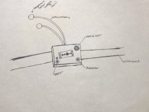
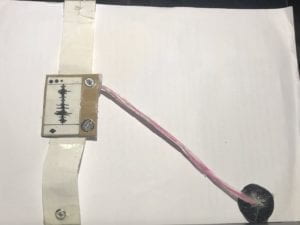
The article, Physical Computing’s Greatest Hits (and misses), sparked an idea in our group, reminding us of the various sensor inputs that a device can use. Specifically “Meditation Helper,” helped our group thinks about a futuristic device we would want to create, because right now devices cannot really interpret mood or feelings well, but in the future, anything is possible. Combining the goals of using interesting sensors to gather inputs and creating a device that processes feelings and mood, the idea was born to have a device be able to sense moods and feelings. As a joke, one member suggested it make people food based on their feelings, and we took that idea and expanded on it, discussing possible specific inputs and corresponding outputs along with scenarios to showcase the variety of moods, feelings, and health responses the device has. To simplify the device, the inputs would be information taken from many sensors on the wrist attachment of the device(see sketch and device below). The signal would be sent to the modem (which for our presentation was a headband and antenna on the device actor’s head). The processing would be the interpretation and cognition of those inputs, taking that information and matching it to stock moods and feelings that would then correspond to certain meals, mostly comforting the user. The output would be actually sending the signal to the smart kitchen and producing the meal. And the two actors would be the user and the device itself (both the wrist sensors and its connection to the processing unit). Compared to the two research projects, unlike the mechanical clock, our device has complex processing like interpretation of many inputs and decision making to decide what feeling or mood the person is having. Also, processing includes identifying the mood/feeling and recognizing which meal to prepare for the user. Compared to the DIY DDR, both have sensor inputs and process relatively complex information. DDR processes timing and keystrokes matching up to dance steps. The output of our device is a bit more complicated as it involves creating a more complex multi ingredient product, a meal, where as DDR’s output is the display of either a hit or miss (although still relatively complex with the display on the screen involved). Our group process started with early discussions of our researched interactive and non/less interactive devices that lead to brainstorming for our personal device. We discussed a lot about AI type devices and devices that are like personal assistants, but we wanted to stray away from spreading existing assistive technology like Alexa and focus on a more specific niche food. I recently read part of a  book called Omnivore’s Dilemma by Michael Pollen  for a corse on Environment and Society, which highlighted an everyday problem of especially Western societies like America and increasingly China as well that lack a culture around food. This causes a dilemma (hence the name) about what to consume on a daily basis. People often have to think about the problem at least three times a day, even causing anxiety about what someone should eat, and what a healthy meal really is. This device can hopefully aid in reducing anxiety coming from the omnivore’s dilemma, especially while it reads health imputes and moods, deciding what to cook for you instead of you worrying about what to eat and what healthy really is jumping on any new fad from food experts.

In conclusion if I would make any future alterations to improve our device, I would also focus on the smart kitchen to develop that futuristic device more, because although our intentions with our current device are to decide what meal to make you and cook it, we focused on the input and processing more than how the food could be made by this device.

A3 Poster (horizontal):

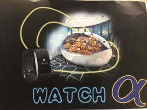
A3 poster for Watch Alfa

Sketch of Device:

Sketch of Device Watch Alfa

Main Device:

Watch Alfa the Device

Recitation 3: Sensors by Isabel Brack

Overview

Overall, this circuit was the most complex so far this semester, not in the amount of wires and connections, but the most tweaking and altering of the code to adapt an Arduino analog in out serial code (because we used the LED as an indicator on whether there was or was not moisture).  We first tested the moisture sensor with code that the moisture sensor link provides, testing the wire hook up and reading the serial monitor. Then we mapped it to an LED and later Servo.

Moisture Sensor Mapped to a LED

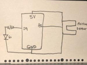
Hand Drawn Circuit Schematic Moisture Sensor LED Mapping

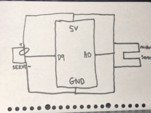
The circuit itself to set up was not too difficult. The moisture sensor connected to the A0 pin, the 5V and the ground. The LED connected to the resistor which connected to the digital 9 pin. The LED also connected to the ground. For the code, we took the example code Analog In Out Serial, which we previously have used to map a potentiometer to an LED. We also had to map the moisture sensor to the light, which was difficult to test its max value or input scale, unlike the potentiometer which is quite easy to test its maximum and minimum. We tested the moisture sensor in the air, on the back of our hands, on our palms, and in a wet paper towel, the highest reading I recorded was almost 700 (although it was restricted to what we personally found), the lowest was 0 in the air and the back of our hands, the palm ranged from about 25- 230. We mapped this to the LED which was 0-255 and read the serial monitor for showing us moisture (input) and light (output), which we relabeled using serial.print. As the sensor recorded moisture the light came on and off at varying brightnesses.

Video of Working Circuit:

In the video we added a bit of water to the palms of our hands to make them damp/moist.

Moisture Sensor Mapped to Servo

Hand Drawn Circuit Schematic  for Moisture Sensor Mapping to Servo

We also mapped the moisture sensor to the Servo motor to test a second output. For this Servo connected to pin 9, 5V and ground and the moisture sensor stayed the same. As we introduced moisture to the senior with the same methods, back of hand, palm, air, and wet paper towel. As we placed it to our palm the sensor picked up moisture and the motor began to turn.

Video of Working Circuit:

In the video we added a bit of water to the palms of our hands to make them damp/moist.

Question 1:

We intended to assemble a circuit that when the moisture sensor sensed moisture would turn the light on at different brightness depending on the amount of moisture. Similarly, we intended to assemble a second circuit that when detecting moisture caused a motor to turn. If the light and moisture combo were to be used in a practical manner, it could be used with agriculture and irrigation letting workers know when the moisture levels of soil have reached a certain degree and no longer need to be watered. It could also be helpful for biology research experiments where moisture levels need to be controlled as a variable of an experiment. The motor system is more practical for automatic large scale agriculture and irrigation where sensors and satellites control all production factors including water and fertilizer. The motor can be particularly helpful for triggering a valve or system to turn off when moisture levels reach a certain level.

Question 2:

Code could be compared to a recipe or instructions because the code gives you the basic instructions on how to get the job done, but in order to change the product/output for your use or preferences you must alter certain ingredients quantities while cooking. And you can add or take out thinks you like or don’t like depending on your purpose. Similarly code gives you a basic foundation that you should flow to get a certain outcome, but personal preference and customization for specific purposes can enhance the product for your specific use.

Question 3:

Personally, I agree with the article  Language of New Media, Manovich explains the third of five components of changes in new media as automation. Automation is the change that I see the most in my everyday life especially in photoshopping apps or social media that have tools to use filters and automatically change an image through doing a certain function like adding a color filter, or stylistic, of light layer design, or even just upping the contrast. It is an automatic function in the fact that it is predesigned to do the same thing to any photo it is applied to. This would be a form of low-level automation.

 As a result of how computers influence new media, human behavior has changed based on the ease and automation of much of new media. People have become obsessed with creating a perfect social media image and constructing an unrealistic version of themselves online. I think this is partly do to how easy it is to alter a photo and filter less appealing aspects. Automations of this altering process allows any person not just someone who is advanced in the realm of editing and technology to alter their own picture. Once people see the ideal edited photo it makes them start to think that is the standard/ norm, not the true photo of themselves. This automation computers have allowed us to have has changed how humans think about themselves and the ideal image of themselves, creating an almost unachievable goal for self image.

Recitation 2: Arduino Basics by Isabel Brack

Overview

Overall, the circuits were interesting to test out as each got increasingly difficult. The first circuit, the fade, was the easiest and the last circuit was the most difficult because of the amount of connecting wires. We did not have time to finish connecting the fourth circuit. 

Circuit 1 Fade:

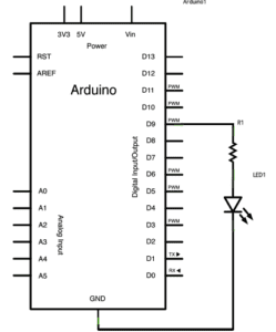
Fade Arduino Schematics

This circuit overall was not too difficult to complete. We connected the LED to ground and to the 220 Ohms resistor which connected to digital pin 9 (according to the code for fading). The light faded almost blinking repeatedly.

Video of working circuit:

Circuit 2 toneMelody:

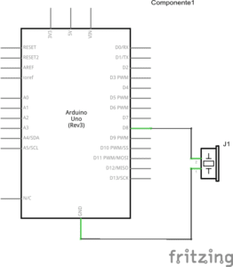
toneMelody Arduino Schematics

This circuit also was not too difficult and we did not run into any major issues. We connected the buzzer to digital pin 8 and ground. The speaker would play a preset melody.

Video of working Circuit:

Circuit 3 Speed game:

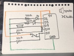
Speed game hand drawn schematics
This schematic is color coded for power (orange) and ground (green). The orange power even though it crosses over many wires only connects to the switches attached to pin 10 and 11.

This circuit was the most difficult only because there were so many wires connecting many components. If you missed a connection it was difficult to quickly find the wiring error because you had to check every single wire connection. We especially found issue with one arcade button as it was not soldered very well and its connection was a bit spotty. For this circuit we connected to 5 different pins, two connecting to the LEDs, two connecting to the buttons, and one connecting to the speaker. There were also two 10 Ohms resistors that are connected to the buttons and two 220 Ohms resistors that are connected to the LEDs.

Video of working circuit:

Questions

Question 1:

Between my personal understanding of interaction and the one I read in Physical Computing, I believe interaction is defined by an input, processing, and output. There are two actors in each interaction, and an input is provided, interpreted or understood, and then responded to with some sort of output based on the input provided. In the passage Physical Computing, interactions was given the analogy of listening(input), thinking(processing), and speaking (output). One actor listens to the other taking in the input, thinks about what they said and what the input means, interpreting how to respond, and then finally responds by speaking bact to them based on their cognition.

Question 2:

We used the 10K resistor to not overload the circuit. In addition, based on some external research of pull-up and pull-down resistors, according to “Pull-up/ Pull-down resistors- explained with calculations” and “Why use resistors with push button or switch with Arduino”, pull-up or pull-down resistors can be used to higher or lower resistance. With digital inputs like a switch turning it on or off (1s and 0s), without a resistor there is an inbetween section of voltage that is uncertain whether it would be assigned a 1/0 or on/off. This is due to noise or interference that surrounds us from other devices. The resistor closes the gap of uncertainty, pulling the voltage in this case down to ensure the switch is either on/off or 1/0.

Question 3:

If I had 100,000 LED lights and the coding and wiring experience to complete this, I would want to make a billboard-sized arcade-style pacman game that could be played in some public space by anyone. The lights at different brightness and colors would light up a for the most part non-changing background maze to play the game, and with a joystick like controller the player could control a small group of lights that would move (by blinking on and off) to show their packpam and another moving group of lights would be different monsters and or collectables for pacman. It would be pretty complex to upload the gaming code to the light board, but entertaining for not just the players also the public.