IxLab(Young) – Robert – Recitation – Group Project

My Definition of “Interaction”

A responsive process includes two or more subjects to get input, digest and produce output. 

Two Researched Projects

“Pulse Room”
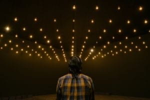
Picture from Lozano-hemmer

In the beginning, my thought of interaction is the scene like a responsive process happens between two intelligence. However, from the first reading The Art of Interactive Design, I was impressed when the author says if we get academic about the argument, the opening of a fridge is an interaction, in which the fridge listens (to the opening door), thinks (with all the processing power of a single switch), and speaks (by turning on the light). This made me rethink that the main bodies in an interaction are not only “intelligence”, but have the possibility to be anything. Then I saw this project which enhances this possibility and offers me new ideas. It is named “Pulse Room” which can record your pulse and add it to one of the bulbs that in all show 100 people’s pulse at the real-time. This is also an interactive project that not only for intelligence. It shows the interaction between people and the device. They used the sensor to make their output to make the device get input. After digest, which in this case might include the transformation of the signal, the device produces output that is the shinning of the bulbs with the same frequency of the participants’ pulse. Moreover, this project also shows the interaction among these 100 people. Though you can not see them face to face, the pulse reflecting on the bulb provides another possibility to connect with each other. 

“Deaf People Hearing For The First Time”

Screenshot From Youtube

Young showed this video in the class and it impressed me because of the reactions of those deaf people. The rapid development of technology makes us have a deeper and deeper connection with our “machines”. But we almost forget that the most common interaction is between people. With this device, deaf people can have the chance to interact with others in a way that is not surprising for us normal people. The way is the conversation. I regard it as the most obvious interaction in our daily life. We hear as getting the input, think as digesting, and speak as producing output. It was hard for the deaf to have this interaction but now it is possible. This project shaped my definition of interaction that the process within the interaction should be responsive but not only a circle. How we interact in the process does matter. Also, though the machine the deaf use in the video seems more like an intermediary, itself also includes an interaction. It gets input that is other people’s saying, digesting as transforming speaking language into another signal and produce output to make the deaf understand.  

Evaluation and Reflection

Upon these two researched projects, I think the second project’s approach aligns better. It tells us more about the meaning of “responsive” and shows us more clearly about the process of getting input, digesting, and producing output. Moreover, it shows us the possibility of doing something helpful to society under the word “Interaction”. Though the first project may approach less well to my definition, it also shows another possibility that we can add elements of “interaction” into the art.

Group Project

Our Poster

For our group project, we first gathered together to discuss our understanding of “interaction” and how to show this “interaction” on a specific device or process that will appear 100 years later.  We reached an agreement that interaction includes input, digest, and output.  So we came to think which part will be changed in the future. I mentioned the film Matrix that all the interaction might only happen in our mind in the future. However, I have the same idea with the betrayer in the film that I don’t want to abandon my physical enjoyment. I still want to drink a bubble tea in real instead of receiving a brain wave. So we decided to change the input. But how to change? 

One slogan mentioned in the reading Introduction to Physical Computing is that we need to make “computers for the rest of you”. Nowadays, our innovation of interaction focuses on the rest of our body. The truth is the controller of our body is our brain. So we suppose that in the future, people will focus on the core of the body, which is the brain. Instead of actually doing something by our body, we can give machines the input just through our brain wave. The digesting will not disappear but will be improved. We think there will be devices to change our brain wave to the digital signal. Also, there will be AI to make the digesting faster and more personalized. However, the output will not change. People still get their commodities or service in real. 
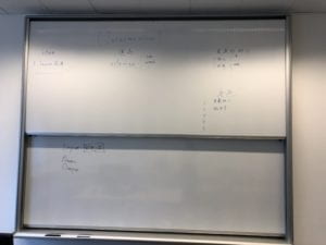
Our mind map, though it is mostly in Chinese.

After ensuring what we want to express, we started to think about how we can show the “responsive” process of interaction. We designed two scenes. One is the main character thinks his shoelace is loose. By sending this brain wave to the device on his head, it transforms his brain wave to a digital signal. After receiving the digital signal, his shoe pulls its lace tight itself, which is the output. This sends a physical feeling back to his brain that he feels good. Including all the steps mentioned above, the whole process is “responsive”. The other is when he wants to buy a bubble tea. He just sends a brain wave to the device, which transforms it into a digital signal and sends it to his personal AI. His personal AI then sends another digital signal to the AI in the bubble tea machine. For the choices of bubble tea, these two AIs starts a conversation. This part also includes the interaction between AIs in the future. This interaction is like our daily conversation I mentioned in the second researched project but it is through the network which means there is no sound but only digital signals. Finally, after listening to the recommendation, the main character makes his choice. The same transformation happens in his brain. Through two AIs, he placed an order. Finally, he gets his bubble tea and he feels happy, which is the output. Also, all the steps mentioned can be collected to a whole “responsive” process. 
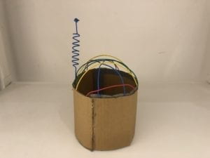
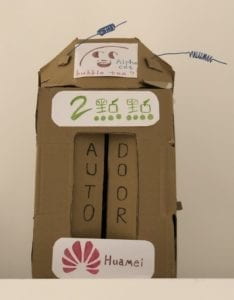
The device that can “read his mind”
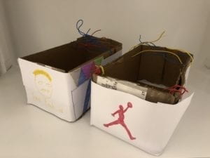
His shoes (though looks like two boxes)
The bubble tea machine and its AI Alpha Cat

In all, our group project satisfies my definition of interaction because it shows a responsive process that includes getting input, digesting and producing output. We mainly focused on the changes in the input part and the improvements in the digesting part that might happen in the future. The responsive processes were shown through our performance that includes two scenes. 
IxLab(Young) – Robert – Recitation 3 – Sensors

Information:

Time: 13:45-15:00, 1 March 2019

Location: 825, 8th Floor, NYUSH

Partner: Sheldon Chen

Preparation:

Materials (as I can remember):

  • Arduino Uno
  • USB A to B cable
  • Breadboard
  • Wires
  • LED
  • Buzzer
  • Moisture Sensor
  • Infrared Distance Sensor 
  • Vibration Sensor
  • Ultrasonic Ranger
  • Joystick module

Process:

Circuit 1: Moisture Sensor

Picture from Moisture Sensor
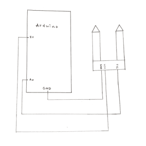
Diagram of Moisture Sensor
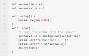
Code from Moisture Sensor

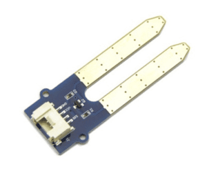
Starting from the Moisture Sensor, we found the code on the website given. It told us we need to use A0 as the analog input so our challenge was how to connect the wires. We recalled what we learned from the last class and connect VGG with 5V, GND with Ground, SIG with A0 on the Arduino. After verifying and uploading the code, we opened the serial monitor and tested the Moisture Sensor with the sweat in our hand (sounds weird). However, my partner won the sweat competition (next time we might update it with LEDs and more wires to make it like a real “competition” ). 

Circuit 2: Infrared Distance Sensor

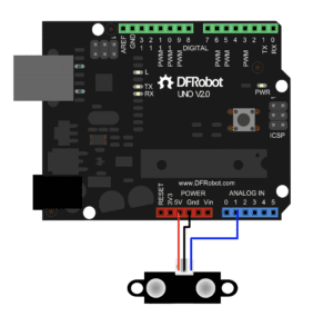
diagram of Infrared Distance Sensor
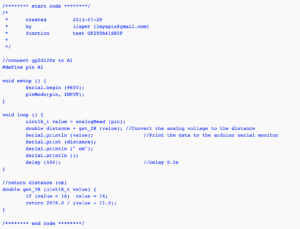
Code from Infrared Distance Sensor

Following the diagram, we quickly built the circuit.

Circuit 3: Vibration Sensor 

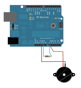
Diagram of Vibration Sensor
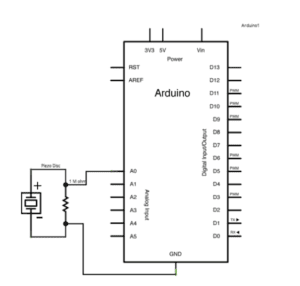
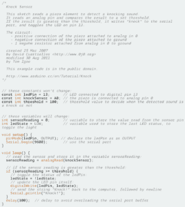
Code of Vibration Sensor
Schematics of Vibration Sensor
Code of Vibration Sensor

We used a LED as the output (By the way, my hands hurt). 

Circuit 4: Ultrasonic Ranger

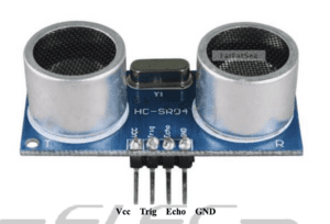
Picture of Ultrasonic Sensor
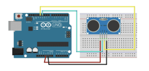
Diagram of Ultrasonic Sensor
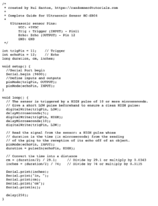
Code of Ultrasonic Sensor

We did not use the Ping code so we connected Trig and Echo into two different Digital pins.

Circuit 5: Joystick module

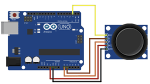
Diagram of Joystick module
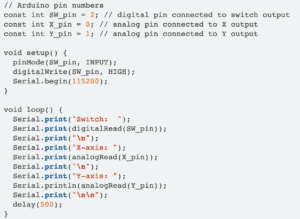
Code of Joystick module

This is my favorite sensor because it reminds me of the game handle.

Question 1:

I intended to assemble Infrared Distance Sensor with the buzzer though failed. For pragmatic purposes, I think it can be used as a doorbell. If someone is getting close enough to the door, the buzzer will ring to remind the host to open the door. It will be much more convenient because the guest does not have to press a button to ring the doorbell.

Question 2: 

Because when you don’t understand how to use or connect a component, whether it is a sensor or an output like a buzzer, you can get information from the code. Like in the code of Moisture Sensor, if you don’t know what SIG stands for, after connecting the simple VGG and GND, you find one interface should be connected to A0 according to the code and then you know it must be the SIG.

Question 3: 

I think the computer influences our human behaviors through what we always mention, the interaction. Here it not only means we interact with this machine but also we also have interaction with the whole behind, which can be the world connected by the Internet or other machines that based on the computer. Now the computer is one of the necessary components of our daily lives. They both are changing, or we can say improving by interacting with each other. 

IxLab(Young) – Robert – Recitation 2 – Arduino Basics

Information:

Time: 13:45-15:00, 22 February 2019

Location: 825, 8th Floor, NYUSH

Partner: Sheldon Chen

Preparation: 

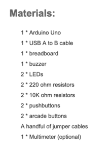
Materials list from Introduction to Recitation 2

Process:

Circuit 1: Fade

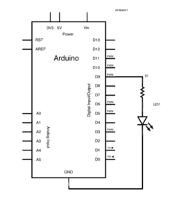
Schematics from Introduction to Recitation 2

Hardware Required: 

  • Arduino
  • LED
  • 220 ohm resistor
  • hook-up wires
  • breadboard
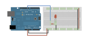
Image from Arduino.cc
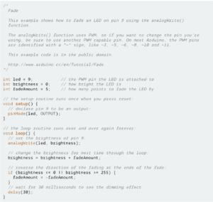
Code from Arduino.cc

As a programmer and circuit builder, when you get both the physical map and the code, everything seems easier. So we just copy and paste the code (Of course we read it carefully and got to understand it), and built the circuit following the physical map. 

Circuit 2: toneMelody

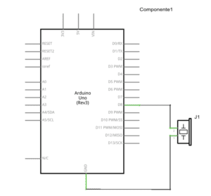
Schematics from Introduction to Recitation 2

Hardware Required:

  • Arduino
  • Buzzer
  • Hook-up Wires
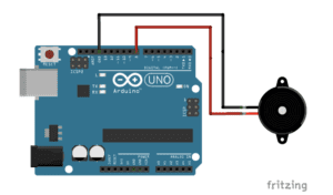
Image from Arduino.cc
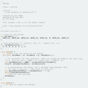
Code from Arduino.cc

Also following the physical map on the website, we quickly built the circuit. After understanding the code slightly, we ran it and heard the buzzer singing. 

Circuit 3: Speed Game

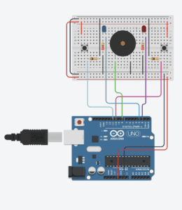
Image from Tinkercad.com
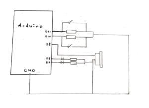
Draft of Schematics for circuit 3

The first time we saw the physical map on the website, we were like:

What???

This circuit is more complex so that for 5 mins we can not figure out how it was connected. Then we decided to use the same method: following the physical map. We built the circuit for more than 5 mins because there are too many wires and it was easy to be confused. The holes and numbers on the breadboard are so small that my eyes felt painful after this. However, we still successfully made it work. 

After we played the speed game for couples of times, we started to draw the schematics. I had no ideas in the beginning. However, instead of analyzing the physical map, I tried to draw by following wires with different colors. By doing so, I finally finished the schematics and knew how the circuit works. 

Circuit 4: Four-player Speed Game

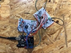
After organizing a team, we worked in cooperation with a due division of labor. For me, my job is to build the circuit for four players with my partner. In the beginning, our idea is to parallel two circuits with the same digital output but with only one power. However, Eric gave us a hint that we actually only needed one Arduino. So we built the circuit which I thought was right and ran it with the code which my partner thought was right. Sadly for us, we failed.  Press of two buttons could not be counted and the numbers on the screen were always zero. There was no more time for us to find the problem, but I think we will try to figure it out sometime. 

Picture of our circuit

Question 1:

 I think interaction is the “communications” between you and your machines. Like using your computer is interaction because once you click on the screen or press on the keyboard, your computer will process to make an output, no matter it is opening a web page or typing some words in the doc. However, as the article mentioned, now what we can do is make “computer for the rest of you”. With physical computing, we can make interactions more than only including your eyes, ears, and fingers. Like the functions on the new LG phone, though they are not the brand new one, which Samsung did the floating gesture first, it still shows the new possibility for people to have new interactions with the devices that we are familiar with. 

Question 2:

If I have 100,000 LEDs, I might use it to build a big phalanx displaying on the top of NYUSH. There will be a QR code on the entrance door of NYUSH. If you scan it, you will see the web app I designed to write down what you want to say or vote for the good sentence you like. The most voted sentence will be displayed on the phalanx and show everybody the writer’s brilliant idea. 

IxLab (Young) – Robert – Recitation 1: Electronics & Soldering

Information: 

Time: 13:45-15:00, 15 February, 2019 

Location: 824 & 825, 8th floor, NYUSH

Partner: Sheldon Chen

Preparation:

Learning to solder: 

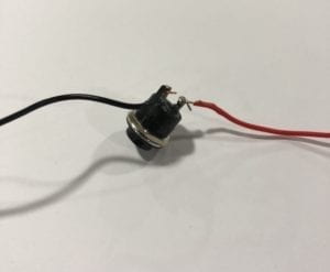
    This is our soldering button.

Our goal was learning and practicing how to solder an arcade button.  We used the soldering machine to melt tin to connect the wires with the metal rings on each side of the button. The problem was that I was a little nervous. My hands were shaking so that I can not perfectly control the soldering pen. It was hard to operate because the wire was fine and the soldering pen is too sharp. When it came to the soldering part, we learned how to take advantage of the metal conduction for a better operation to make the solidified tin shiny.

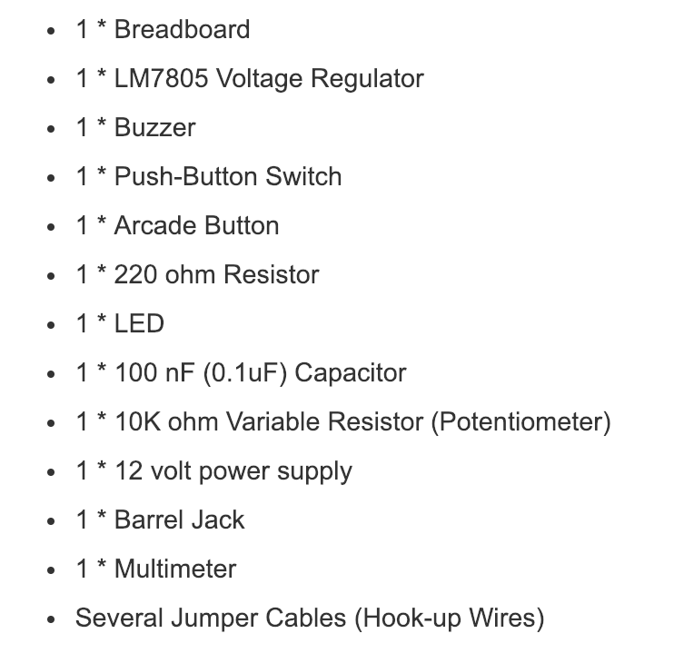
Materials: 

Materials list from Introduction to Recitation 1

Process:

Circuit 1: Door Bell

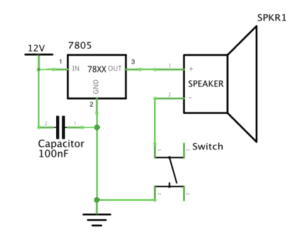
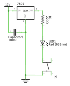
Schematics from Introduction to Recitation 1

We first selected the needed materials in this circuit, which are: 

  • Breadboard
  • Voltage Regulator
  • Capacitor
  • Buzzer
  • Switch
  • Couples of hook-up wires
  • 12-volt power supply 

Then we met our first and the biggest question:

How can we build the circuit according to the schematics? 

We both learned some knowledge about the circuit back to high school, but this was the first time for us to try to build it on the breadboard. What’s more, the regulator and the capacitor are two electronics we never used before. 

However, we came up with an idea that we can use the numbers labeled on the wires to distinguish the direction of current flow. First, we collected the power with the regulator which was the most simple one. Then, for the regulator, we collected “2” to the cathode of the capacitor and “3” to the anode of the buzzer. By using the number, we finished the building process.

But when we turned on electricity, the buzzer kept ringing and the switch didn’t work. 

So we turned off electricity and started to check. Because the buzzer was working normally, we believed that the problem was from the switch. We removed the switch and the buzzer could still work, which confirmed our suspicion. We looked twice to the schematics of the switch and found that we had collected wrong legs of the switch. 

This time we changed the direction of the switch and finally succeeded!

Circuit 2: Lamp

Schematics from Introduction to Recitation 1

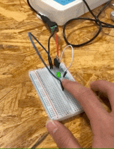
This time was easier because we already had the basic circuit. We removed the buzzer and inserted the resistor and LED. Each Leg of the resistor and LED were in a new line on the breadboard to avoid short circuit. 

The GIF of our 🌟LED

Circuit 3: Dimmable Lamp

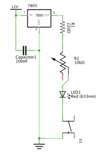
Schematics from Introduction to Recitation 1

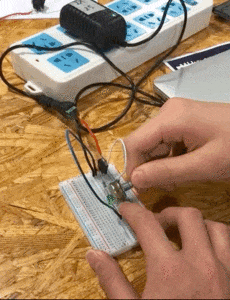
Also by distinguishing the number on the variable resistor, we inserted it into the circuit. 

The GIF of our dimmable 💡

Extra: Dimmable Buzzer

Since there was time, why not to create something new?

We changed the LED to the buzzer but found that no matter how we turned the variable resistor, there was no sound. We thought that it might because of the 220-ohm resistor that made the current too small. So we removed the 220-ohm resistor and BOOM!

Question 1 :

I do think there is interactivity in the circuit we built, but not a strong one. The author defines interaction as “a cyclic process in which two actors alternately listen, think, and speak”. Like the fridge in the article, in this process, the circuit listens to the pressing switch, thinks with also all the processing power of a single switch, and speaks by ringing the buzzer or turning on the LED. For me, I listen to the output of the circuit, think what I want to do next,  and speak by turning off electricity or rotating switch of the variable resistor. 

Question 2: 

 I think Interactive Design provides creativity and Physical Computing offers the possibility.  Mindstorms in your mind, no matter they are cogent thinking or fantastic imagination, give birth to new ideas maintaining great creativity. Physical Computing makes those ideas real in life and keeps improving them to be better. Compounding the two is like connecting the abstract and the concrete to create Interactive Art. Like Zach’s recent project, the eye-tracking system for disabled artists. Interactive design gave him ideas and physical computing made it possible. The process might be hard. But when Interactive art finally shows up, you can see how inspired it will be, just like what Zach did.