4th Inter Lab Documentation

Lab Time:10/11/2019

Partner:Andrew Xie

Components Used:

For Steps 1 and 2

  • 1 * 42STH33-0404AC stepper motor
  • 1 * L293D ic chip
  • 1 * power jack
  • 1 * 12 VDC power supply
  • 1 * Arduino kit and its contents

For Step 3

  • 2 * Laser-cut short arms
  • 2 * Laser-cut long arms
  • 1* Laser-cut motor holder
  • 2 * 3D printed motor coupling
  • 5 * Paper Fasteners
  • 1 * Pen that fits the laser-cut mechanisms
  • Paper

Lab Content:

  • Build a controlable rotating stepper with H bridge
  • Build a drawing machine with two controlable motors

Detailed Description:

Step1:  Build a stepper

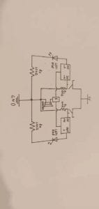
This step aims at building a circuit to control the stepper, using the  code of Arduino>File>Examples>Stepper>stepper_oneRevolution. Below is the sketch.H-bridge circuit diagram

This step is pretty easy because as long as you are following the instruction given, connecting the circuit right and using the right code, you can achieve this. One thing that particularly interested me is the connection of H-bridge, which needs to be built very carefully, for each of its pin has different use. And sometimes we even need to make sure that all of its pins is plugged into the breadboard.

12

Step1:  Build a stepper

Based on the circuit of step 1, we now need to add a potentiometer into the circuit and use it to control the stepper. Because the 42sth33-0404ac Stepper Motor is a 200 step Motor, we need to make sure we’ve changed the value of variable Steps from 150 to 200. And map is needed to define the scope.

3

5

During the test there was a problem. When I was trying to make the stepper work with the potentiometer, I found the potentiometer moved much faster than the stepper. And by changing value of the variable controling the speed, I successfully solved this problem.

Step 3: Build a drawing machine with 2 steppers

The third step is simply to assemble the arm and start the stepper with a partner, but it seems that the pen is not long enough to sometimes touch the paper. It was a wonderful feeling to see the Arduino and stepper paintings.

67

(That’s our picture, drawn by our machine.)

Q1:

I’m interested in AI learning building. AI could be used in fields like translation or recognization, and some could even taken into art aspects. Like some AIs nowadays could restore those damaged painting and even paint by themselves.

Q2:

Comparing our work to the shadow chaser , for which the artist uses computers to control robots with the shape of metal skeletons to beat drums, and further uses robots to express human situations or emotions. And actors to enhance the robot’s performance more subtly.It’s like the stepper on reception, which can play instruments by rotating to different angles, or motor, which can support robot walking. The more complex combination of drawing machine is the work of these artists.

3rd Inter Lab Documentation

Lab Time:9/22/2019

Partner:Andrew Xie

Components Used:

  • 1 * USB A to B cable
  • 1 * breadboard
  • 1 * buzzer
  • 1* Ultrasonic ranger
  • 1* Infrared Distance Sensor
  • 1 * 10K ohm Resistor
  • 1 * Arduino Uno

Lab Content:

  • Ultrasonic Ranger Circuit
  • Infrared Distance Sensor Circuit

Detailed Description:

Infrared Distance Sensor Circuit

We used Infrared Distance Sensor to do the first project, but compared with the next ultrasound, the accuracy is not very accurate. Perhaps infrared radiation received more interference, leading to data changes.

Ultrasonic Ranger Circuit

Next, the focus of our work is on ultrasound, because we found through experiments that the accuracy of ultrasound is higher, and can measure more distances. With the change of map, we connect buzzer into the circuit. As the distance increases, the sound of buzzer becomes smaller and smaller.

1

2

It is worth mentioning that there are four ports of ultrasonic electronic components, and the two ports in the middle can not be separated for transmitting ultrasound and recovering echoes.

Question 1:

I used the Ultrasonic Ranger and Infrared Distance Sensor as assembled objects. For application in reality, I think it should mostly be used somewhere the distance need to be measured, like an automatically-controlled door or velocimeter.

Question 2:

Because just like recipe and tutorial, the code show the computer how to achieve one goal by teaching them with an understandable language. Besides, the code, as well as recipe and tutorial, highly require for strictness. Doing one step wrong could result in a fatal error or deviation.

Question 3:

Nowadays, we seems to get all kinds of information from the internet and our computers. It could even been concluded that we spend a greater amount of time on computer than anything. So the computer technology indeed plays a utterly important role in our lives and impacts us implicitly.

2nd Inter Lab Documentation – Leon Ding

Lab Time:9/20/2019

Partner:Andrew Xie

Components Used:

From Arduino Kit:

    • 1 * Arduino Uno
    • 1 * USB A to B cable
    • 1 * breadboard
    • 1 * buzzer
    • 2 * LEDs
    • 2 * 220 ohm resistors
    • 2 * 10K ohm resistors
    • 2 * pushbuttons
    • A handful of jumper cables

From cart:

    • 2 * arcade buttons
    • 1 * Multimeter (optional)

Lab Content:

    • Fading Lights
    • Tone Melody
    • Speed Game

Detailed Description:

Fading Lights

This project used the Code from Arduino>File>Examples>03.Analog>Fading. And below is the schematic graph of the circuit.

Though we thought the first one should be pretty easy, but in fact it’s just this one project that takes us the longest time. 

1

As you can see, the LED light was simply flashing rather than fading. The first thing occured to us was there must be something wrong with our code. So we checked our code only to find no BUGs. And we asked the instructors for help and it turned out that the circuit connection had no problems too.

When we didn’t know what to do, Eric stopped by, checked our Arduino borad and pointed out a subtle error: 

The reason why we’ve got a problem is that the pin 13 was connected as the output terminal and it can only control basic 0/1 or HIGH/LOW information (digitalWrite), and to control the dimness, thus we need to use a pin to give analogWrite results. Finally, we change the output end to Pin 9 and it was a success in getting the fading effect on the led lights.

Tone Melody

This project used the Code from Arduino>File>Examples>02.Digital>toneMelody. And below is the schematic graph of the circuit.

This part was pretty easy, and with the help of sample code, we quickly built the circuit and tested. It turned out that we made it.

Speed Game

This project used the Code from https://www.tinkercad.com/things/6MzvN5rlZlr-race-the-led-spring19. 

And below is the schematic graph of the circuit.

The third Circuit was very challenging for me and my partner. Because we thought that the installation method according to the design drawing would make the wiring messy and ugly, we redesigned it to make the circuit more beautiful in a symmetrical way, which, of course, cost us more time.

Due to time limitation, we did not build Circuit 4, but we found other team members to play the game together.

Question 1:

To be honest, I’m using all kinds of interactive technology to type in these words for my documentation: from keyboard, monitor to CPU, all of them are a reflection of interative technology. We give something as an input and it returns us with some results. As for the circuits we build, we offer some changes (like the rotation of variable resistors) and it feeds back some changes (like tone/brightness changing or victorious ringbells).

Question 2:

We use the 10K resistor with the push button to keep the control part circuit under protection and won’t encounter any short-circuit problems. If we use a resistor with lower resistance, there would be a great chance that once we leave the switch on accidentally and connect the current source, it would become a short-circuit so we must use a resistor with great resistance like 10K.

Question 3:

I would make use of them as general facilities in some poverty-stricken areas in China, where the lack of brightness (like traffic lights, streetlamps and family-use lamps) limit people’s life qualities in a great way.

1st Inter Lab Documentation – Leon Ding

Lab Time:9/6/2019

Partner:Andrew Xie

Components Used:

    • 1 * Breadboard
    • 1 * LM7805 Voltage Regulator
    • 1 * Buzzer
    • 1 * Push-Button Switch
    • 1 * Arcade Button
    • 1 * 220 ohm Resistor
    • 1 * 10K ohm Resistor
    • 1 * 10K ohm Variable Resistor (Potentiometer)
    • 1 * LED
    • 1 * 100 nF (0.1uF) Capacitor
    • 1 * 12 volt power supply
    • 1 * Barrel Jack
    • 1 * Multimeter
    • Several Jumper Cables (Hook-up Wires)

Lab Content:

    • Door Bell Circuit
    • Lamp Circuit
    • Dimmable Lamp Circuit
    • Solder

Detailed Description:

    • Door Bell Circuit

doorbell

(The draft of the circuit we should build)

1. Connect the breadboard with current source (Positive pole with + and Negative pole with -)

2. Plug in the Voltage Regulator.

For this step we encountered some trouble for not knowing which foot should be connected to which side. Then we asked the prof and finally found the answer on the website (as this picture shows below).

7805 voltage regulator symbol

3. Connect the buzzer and button.

It’s where we encounter a very interesting and worth thinking problems. We plug the button in and run the whole circuit, only to find out that the buzzer kept ringing and the button didn’t work. When we had no idea how to deal with this problem, it suddenly occured to us that we might connect the button in a wrong way. And we turned it 90 degrees, it worked.

    • Lamp Circuit

lamp

    • Dimmable Lamp Circuit

These two experiments are bascially the same as the buzzer one, except the dimmable lamp circuit need a Variable Resistor as a dimmer .

    • Solder

The whole production process is very simple, just take care not to touch the welding pen tip with your hands, and when removing the rubber part at both ends of the wire, it should be longer, or it will be difficult to plug into the bread plate, because we did not realize this, it was very difficult to carry out the experiment later.

Q1:

I think the part of the circuit which reflects the interactive thoughts most is the switch. By using this little button, we make the whole circuit’s on/off under our control, and an action of pressing the button could get a interactive feedback (like buzzing or lighting). So that’s why I consider that interactive.

Q2:

Maybe we should bring human-beings factors and operation into the conversation with art work or design work, which would obviously make the whole thing seem more controlable and interactive.