Lab Report 4

After read the psychological behavior of insecure, in which model the robot can sense the barriers on every side and avoid them using a whisker brick. I decided to make it because sensing the environment and avoiding danger (where it is “crashing” here). It is the basic behavior for an creature to maintain existence and the success implementation of it will enable us to design more complex behaviors without need to worry about its safety.  

I studied and found it was difficult for us to make a whisker brick, as I didn’t have sensors to sense the bent of strips, which perhaps requires a lot of  amperemeters to capture the resistance of the strips before and after the bent, or pressure sensors to capture the pressure caused by the bent. Thus I chose a different method for the same result.

At first I thought of the supersonic sensor, but the I realized it can only can sense whether there are barriers in the front or not, but cannot sense from which direction exactly, I.e. left, middle or right. Thus, I thought of the infrared sensors as it has five inputs and outputs. 

Surprisingly, the professor showed me that by using mobile phone cameras, I could actually “see” the  infrared lights. I intended to use all the five infrared sensors but found only 3 pins could be used as analog IO

Only P0 P1 P2 can be used as analog IO

So I decided to use the leftmost, middle and rightmost ones which then allowed the chip to measure the difference of the output and decide the direction of the barriers.  

Finally it successfully simulated the “insecure” behavior.


The main difference between my design and that in the Braitenberg is that it uses whisper bricks in the implementation, while I used infrared sensors. Thus, my implementation still couldn’t sense the barrier in every direction, yet the limitation of equipment and pins both made the original design difficult to happen.  Yet since the robot can turn around and always makes its sensors to the direction of its movement. The different doesn’t affect much to the final result. 

Still, in terms of changing the design, I would connect the supersonic with the chip as well. I found that there are another three analog IO in the microbit but somehow robotbit doesn’t provide the correspondent pins on the board. Ny next step is to find how to connect them and make the psychological behavior simulation more accurate.

Bio Robots Lab Report 3

During the lab, we firstly built the robot as the instruction manual suggest.

Unpack:

Install steering engine and supersonic control board:

Install the motor:

Install the wheels:

Install Microbit and Robotbit central control board:

Install the supersonic detector:

Finished!

Really, be careful about the screws, as each of them is specific for one purpose. Don’t confuse about them.

After that, I programmed the cat (light, motor, servo and supersonic sensor):

It has two modes: needy mode when pressed A, for which the cat will chase after you; and careless mode when pressed B, for which thee cat will turn away and ignore you when you wave at her.
Press A + B to turn off the cat.

Codes shown below:

The light part was the most difficult, as the show function must be used carefully, or the program will raise an error. For example, the show function can’t be used after the clear function.

In order to make the cat’s head turning behavior more fun, I used the random function so that the cat may turn different angles in different times. 

I also successfully made the cat move in a constrained space:

Code:

I tested for hours for it. Firstly I mistakenly connected the wires in VM pins, and I did successfully made them move forward. However I failed to make the cat spin. Secondly I noticed I had to use the pause and stop motor function to slow the program, or the cat wouldn’t be able to turn even if the supersonic detected a barrier. I assume it is because supersonic module takes time to detect and process, while the buffer for the motors are still making them going forward.  

Lab Report: Robot Brain

Intro: 


In the lab today we explored the basic functions  of Microbit  microprocessor: software programming, sensors and outputs, as well as a simulation of a basic animal behavior.

Exploration on Software and Hardware

After reading the guides sent by professor, we firstly studied how to program the chip using various tools, including Microsoft-provided API support Scratch and JavaScript with a virtual simulation, we also tried python API provided by the chip company.

Enlarge

d
Microsoft Javascript API

Enlarge

捕获sdv
Microsoft Scratch API

Enlarge

dbhsrg
Python API

To explore the basic functions supported in the chip, my teammate and I tried different basic programming, including loops, playing music and LED lights.

Programming LEDs to show words

Enlarge

b20a377f24cce6e1890f912ebc5a48d
Programming LEDs to show a picture

Enlarge

d-1
LED programming codes

During the practice we successfully find the “Easter Egg”: when simultaneously press A and B button in the factory flash, we can launch the snake game.  So far we found there was little difference between programming for the chip and for a computer (especially the screen).

By study the code blocks in the JavaScript API, we discovered that the chip integrates sensors as following: A light sensor, a temperature sensor, acceleration sensor (perhaps 3 gyroscopes), a magnetic sensor, a wireless card. 

We also found a picture describe the pins, which deserves further knowledge  and exploration:

Enlarge

microbit-pins
Description of the pins

We used a oscilloscope to test the output pins, ad found an interesting result. We didn’t program any output code to the chip, but the oscilloscope showed a square wave on the 3V output pin, for which We researched online but found no explanation. At last we had to suppose it was the default output of the chip.

A general description of different compartment:

Final Build:

Firstly, we programmed the acceleration sensor, the wireless card and one pin on two chips. Then we connected the pins (0, 3V, GND) on each chip with a motor.  When the acceleration sensor sensed a tilt around a certain axis, the motor it connected will turn in the opposite direction.

It is to simulate the neural reflex of an animal to stand still when receiving a force from the environment  pushing it to one side. the chip represents the receptor, the wires are neuron fibers and the motor is effector (which would be connected to “muscles” in real robots). 

We then programmed the wireless module to represent the communication between animals. When an animal(chip) senses the danger, it will notify other animals(chips) around it to prepare in advance, so that they can reduce the damage from the environment. we used a tiny turn in the motor to show the preparation.

Enlarge

捕获2
Program of Neuron Reflex and Communication

Reflection:

There are still many improvements we can achieve. For example, we thought later that it would be better for us to use the buffer on the chips. When a chip receives a notice of danger from others, it can store the voltage output commands into the buffer, so that it will react quicker when facing its own danger. It would be a more accurate representation for the behaviors we simulated. We were also interested in the unsolved mystery of oscilloscope mentioned above, but sadly we were short of time. Generally speaking it was a very interesting lab, and there are more applications of it for us to explore.

Source:

Microsoft Scratch and JavaScript API: https://makecode.microbit.org 

Firmware picture description: https://tech.microbit.org/hardware/ 

Chip pin picture description: https://microbit.org/guide/hardware/pins/   

Lab Report: The Game of Life


Introduction:

The rule of “The Game of Life” in two dimension is defined on an infinite plane divided into a number of adjacent square, with each one surrounded by eight. Each square is considered as a “cell” with two attributes: Alive & dead, with the rules of altering between the to attributes shown below:

       If cell == alive {cell = dead if surrounded by n < 2 or n > 3 cells}; (living condition)

       If cell == dead {cell = alive if surrounded by n == 3 cells}; (reviving condition)

One “Generation” is defined as applying the two rules above simultaneously once. 

This report studies different algorithms which implement it, and how the rules behave on different two dimensional spaces through the algorithm.

Algorithm Analyzation:

1.  In two dimensional flat plane, the algorithm realizations is coded in  C#, which core part includes defining a three dimensional array to express a 100 x 100 2D plane and the correspondent cell value: 

private int[][] cellValues = new int[100][];

for (int r = 0; r < 99; r ++) {cellValue[r] = new int[100];}

using the “surrounding function” to tell how many other cells surround one, for example:

private int surrounding(int c, int v)
{if cellValue[r][c - 1] > 0 {count ++};}

Then it pass the count ‘g’ as the cell value to the correspondent cell value:

cellValue[r][c] = g;

To make one generation, the algorithm firstly calculate the cell value of every cell on the plane, then if a cell’s value is above 0, it will be activated, else it will be deactivated in the GUI codes.  

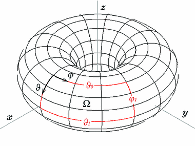
2. Another algorithm realized it in two dimensional toroidal surface via Python.

Enlarge

430402_1_En_3_Fig1_HTML
A toroidal surface

 The algorithm uses similar idea to tell whether a cell is alive or dead after one generation, that is, first calculate the cell value of every cell, then update the attribute of each. However, to express a toroidal surface in a regular two dimensional list: 

total = int((grid[i, (j - 1) % N] + grid[i, (j + 1) % N]
+ grid[( i - 1 ) % N,  j]+ grid[(i + 1) % N,  j]
 + grid[(i - 1) % N, (j - 1) % N] + grid[(i - 1) % N, (j + 1) % N]
+ grid[(i + 1) % N, (j - 1 ) % N] + grid[(i + 1) % N, (j + 1) % N])/255)

What’s special here is the mod operator (%), when a counting index goes out of the plain, it “drags” the index back. For example, in a 10 x 10 plane, the point (9, 9) connects to: (8, 9), (9, 8), (8, 8), (8, 0), (9, 0), (0, 0), (0, 9), (0, 8). Thus, if being observed on a 2D flat plane, a pattern will appear from another side of the plane if it reaches one boundary.

Rule Analyzation:

The report specially studies the reviving condition: why the conditional number is n = 3 but not others, using the Python code on toroidal surface.

The Python code provides several stable pattern on n = 3. Among them, A Glider is a small pattern moves diagonally, and a Gosper is a larger pattern that keeps firing Gilders. As they can represent the behavior of motion and reproduction, the report uses them as two study objects.

Enlarge

Rules_of_Conway%27s_game_of_life_-_Glider
A Glider

Enlarge

File:Gospers_glider_gun
A Gosper

By experiment it shows when n = 4 or above the glider stays put without any motion and the Gosper ceased to a pairs of a-group-of-four blocks, which is a classic static pattern in Game of life. When n = 2, both patterns quickly expand and fill the whole surface with random moving patterns. Other experiments reveal similar results.

Enlarge

Figure_1
A chaotic pattern in n = 2

The experiment shows that it is reasonable to set the reviving condition to n = 3, as when n < 3 it is too easy for a cell to revive and the surface will be filled with chaotic moving patterns. and when n > 4 it is relatively difficult for cells to revive, thus the active patterns in n = 3 condition will be likely to stay stationary. n = 3 may be the rule for existing the most number of stable patterns.

However, further experiment find in n = 2, a flat plane is slower than a toroidal surface to become chaotic. Thus, it is likely that the reviving condition n is connected to the type of the space in order to create a rule with most stable patterns. For example, in 3D,4D Euclid space, or Rehman space the best reviving condition may not be 3. A correspondent function: best reviving condition = f(space type) may exist.

A study on 3D Euclid situation done by Carter Bays shows there are more cases in Game of Life on different spaces for further exploration.

Enlarge

捕获-1
A pattern in 3D space

Sources: 

MATHEMATICAL GAMES The fantastic combinations of John Conway’s new solitaire game “life”, by Martin Gardner, Scientific American 223 (October 1970): 120-123. https://web.stanford.edu/class/sts145/Library/life.pdf

Candidates for the Game of Life in Three Dimensions’, Complex Systems 1 (1987) 373-400, Carter Bays, Department of Computer Science, University of South Carolina, Columbia, SC 29208, USA, https://pdfs.semanticscholar.org/c865/e0d19f53ba646e076d6e542e1002c92fd3ad.pdf

C# code.
https://code.msdn.microsoft.com/windowsdesktop/Conways-Game-of-Life-75508f8f

Python code.  https://github.com/electronut/pp/blob/master/conway/conway.py