CONCEPTION AND DESIGN:
It is a collaborative drawing machine aims at promoting and inspiring collaborative work, cooperation and communication. In real case it could be used as an ice-breaking game; as the cooperative task provided is designed to be both simple (in terms of abstraction: i.e. it does not require players to manage a company together, but simply drawing a picture), but also difficult (in terms of collaboration: without collaboration it is almost impossible to finish the task ) it may also be used by researchers to study how human beings interact with each other in a collaborative work. The device requires 4 players to play with. In front of the m is a large screen with a special pen on it:
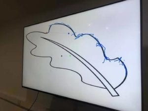
Notice the 4 colorful circles in the screen and the lines connecting them. These together are the pen. Three players will have a handy device in their hands, which contains a “spin-able” part. Players spin it to control the rotation of each circle on the pen. The last player has 2 buttons in hand, the red one is to draw (from the tip of the pen which is the red circle) and the black button it to undo the previous stroke:
three most important designs in this project are: the rotation control unit. The handle and the style of the pen. With the development of our project the design of these three kept changing.
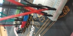
For the spin control unit, the ideal choice is to use a rotatory encoder. We tried it for several days, but then we realized we were facing a fatal problem. (The only time I stayed overnight since college is to solve the problem) with the help of Tristan I almost hacked the microcontroller of Arduino Uno but finally failed (It will be detailed recorded in the next part). The second alternative is quark: to use motor inversely, as we learned at class if we spin a motor it will generate electric signals. But then I realized it needs complex circuits to make the motor able to send out signals in two rotation direction. As the due time is approaching, we have to go back to potential meter. A drawback is that I can only rotate it 360 degrees then got stuck. In observing the players in ima show we find occasionally it slightly affects the performance of the device.
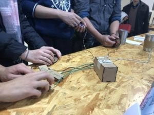
We paid attention to very details of user experience, and the handle is designed very smartly using human engineering. The shape of it fits very well with human hands (see the pic above) and people are happy holding it. We laser cut the boards and put them together. I suggested of using 3D printer before but steve reminded me that there are some small and delicate parts in it and 3D printer is not accurate enough.
As for the style of the pen. We pursue a simplicity in the design of the shape, yet we, again, paid attention to very details of user experience. The color of each circle corresponds to a color tape in the players device. We adjusts the radius of the circle, the size of the circle, the size of the pen stroke many times and ask people to test different versions to hasve best visual effect. The function of the pen is actually inspired by a visualization of Fourier transformation, but I’ll stop talking about math here.
FABRICATION AND PRODUCTION
#A Full Record on Rotatory Encoder#
To me it is the most exciting part. Indeed as Rudi said we should have changed our direction the minute we realized the problem, but my problem is that I could not resist new knowledge (A conflict on pin interrupt?? what’s that?? & I need to control registers in microcontroller to solve it? cool!). Although I failed, that night offers me knowledge and experience that I could hardly get in class, and I’m not regret of that.
This part is also a review for myself about what I learned in that breezeless night.
1.
The problem starts with the library that use the rotatory encoder: it asks as to make an object:
Encoder myencoder
Then call the counting function like:
encoder.counting()
yet weirdly we don’t specify pins here! After Steve tried every pins he finds only when we connect the encoder to pin2 and 3 it works. But we need to connect 3 encoders on the Arduino. Anyway this default use of pins is weird so i checked the source file in cpp.
In the source I found many unfamiliar things: some hexadecimal value assignment to a constant called PCINT, and another called some MASK, a function call “sei()” appears in the middle of nowhere, a function define “ISR()” without any return type… But I do recognize one lines: digitalRead(2) (and 3).
2.
Tristan gives a simple solution. He suggests me to copy paste the file, reset the pins in the digitalRead, then I can have to different objects in my code using different pins. But the IDE raised errors of “redefine variables”, then Tristan reminds me to change all the variables to avoid that. In doing it most of the problem got solved, with only one left: “Error: redefinition of __vector_5()__”.
3.
I scroll the codes up and down without finding and words in the text that looks like a “__vector 5__”. Finally I realized it is a situation I had no experience before, and it might has something to do with all the “sei”s and PCINTs above. Then I google.
after about 1 hour I had some basic ideas about it
#vecter 5 is a variable of Pin Interrupt that governs a range of pins including pin2 and 3.
#A PIN interrupt can be considered as a event listener, when the value on a pin changed, it will trigger the interrupt, which will stop the current calculation in processor and run a new function
# the function is ISR()
#There are three pin interrupts: vector 3 4 5: they are not defined explicitly: the variable PCINT refers to a register with 2 bits that controls the open and close of a pin interrupt; as each interrupt governs a range of pins, MASK is another register that specify a certain pins to listen to.
#sei(); means to start monitoring interrupts
4.
That’s why it specifies pin 2 and 3. Therefore if I could set the code to use a new pin interrupt, say vector 4, I could set new pins and solve the problem. Understanding all the theories in the next several hours, the last thing to do is to study the documentation of the microcontroller on Uno: basically to find which interrupt corresponds to which PCINT and MASK register digit and correspond to which pins.
In fact it worked. I changed the pins and connect it to the encoder, it gives correct output. But when I tried to put two together, there is always one of them not working. I did various experiment and found one thing: as mentioned I copy pasted the codes so I have two of them compiling together, only the encoder connected to the code that is firstly compiled works. It means there are still some hardware resource that are shared by the codes.
Then I found the code refers to another library, a look at it shows it is a timer library uses processor clock pulse, other types of interrupts (there are other types besides pin interrupts) …. Fine.
——————————————————————-
We missed user test because on it, yet we conduct our own user test later. many useful suggestions were offered and I have recorded some of them in the first section. The idea of different color circles is a feedback from the users, also based on feedback I improved the rotation algorithms to make the drawing process more smooth….
CONCLUSIONS:
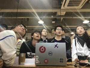
It is a great success in IMA show. There are always people in front of our table. Strangers came together, had a great time in this collaborative game, and some of them even become friends and exchanged wechats. Among them, one representative from the manufacturer of Arduino is very interested in our project. Hearing our problem in the encoder, he assed steve’s wechat and told us he could help with the problem and provide us with better equipment to remake it. In general the final project does not fail us.
*Interestingly, as a work focusing on collaboration, it is also done collaboratively. Steve and me have been partners since midterm and we worked together extremely well. Here I would like to show my gratitude to Steve.
*At thus end of the semester, I would also like to say thanks to Rudi, for… well for everything in these two semester.