Recitation 4. Drawing Machines by Frances (Fan Yuan)

Instructor: Marcela

Materials:

Step 1 & 2:

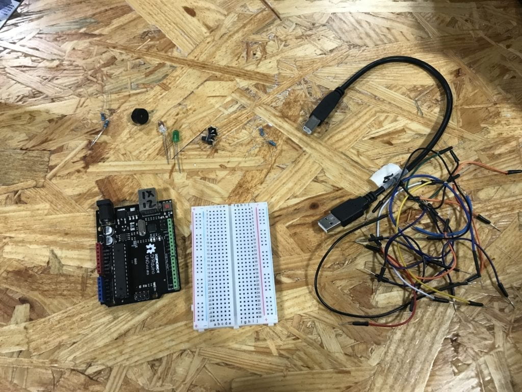
42STH33-0404AC stepper motor,SN754410NE ic chip, power jack, 12 VDC power supply, Arduino kit and its contents

Step 3:

2 * Laser-cut short arms, 2 * Laser-cut long arms, Laser-cut motor holder, 2 * 3D printed motor coupling, 5 * Paper Fasteners, Pen that fits the laser-cut mechanisms, Paper

Process:

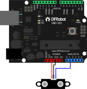
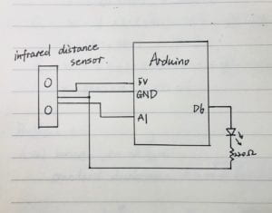
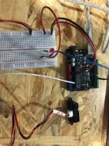
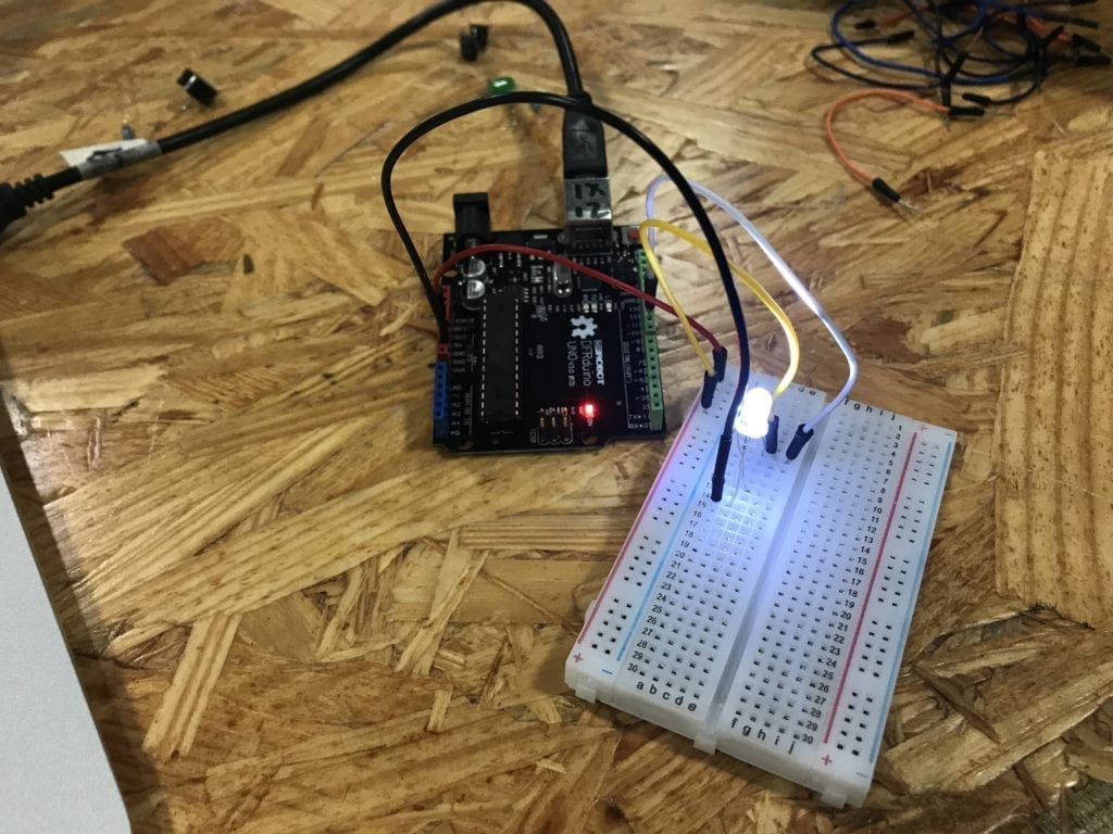
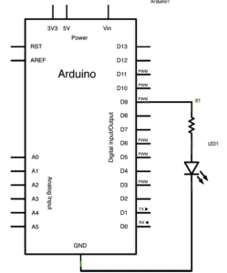
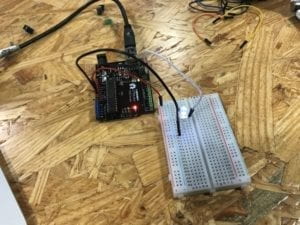
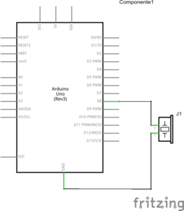
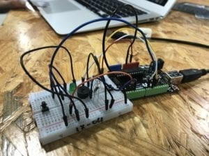
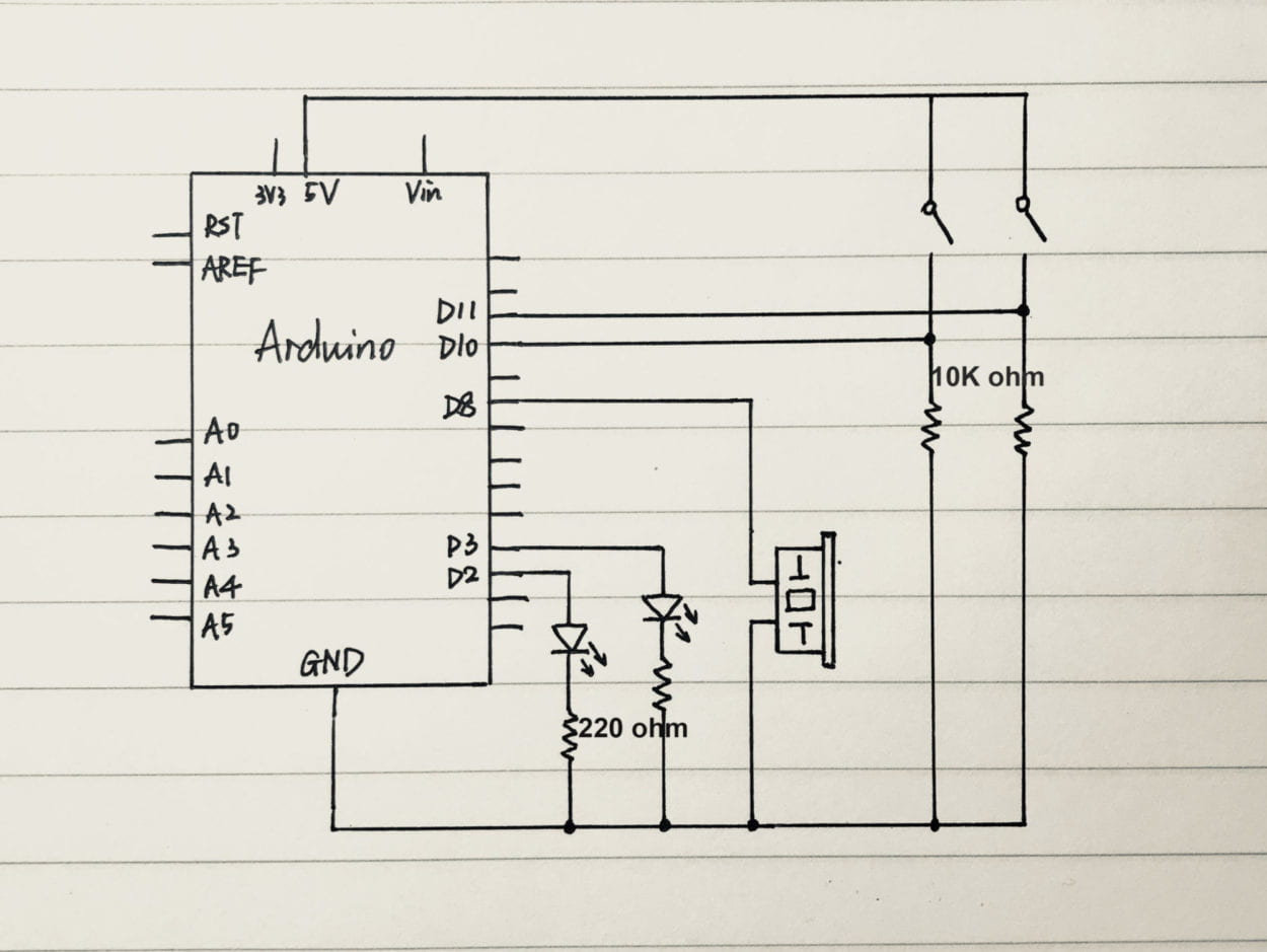
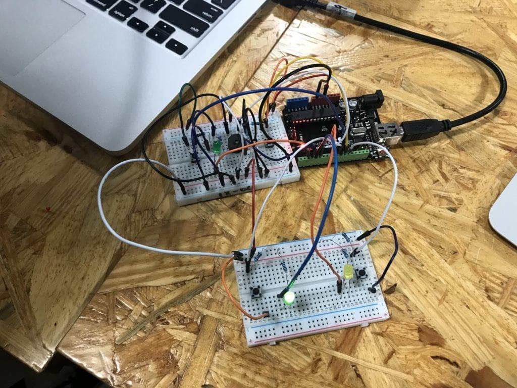
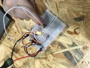
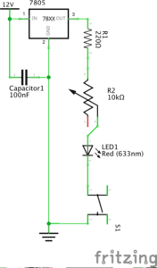
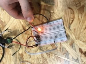
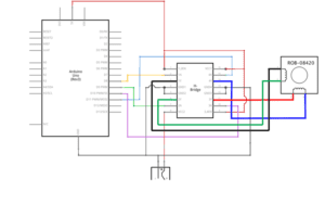
Step 1: Build the circuit

This was the first time in recitations that we build a circuit on our own. The circuit is a bit complicated, but as long as we follow the instructions and make sure every wire is connected correctly, it is not difficult to build. One important thing is to identify the front of the IC. It has a semicircle at the front and the pin to its left is pin 1.

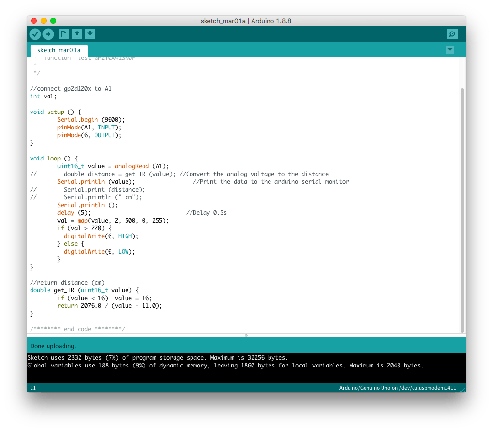
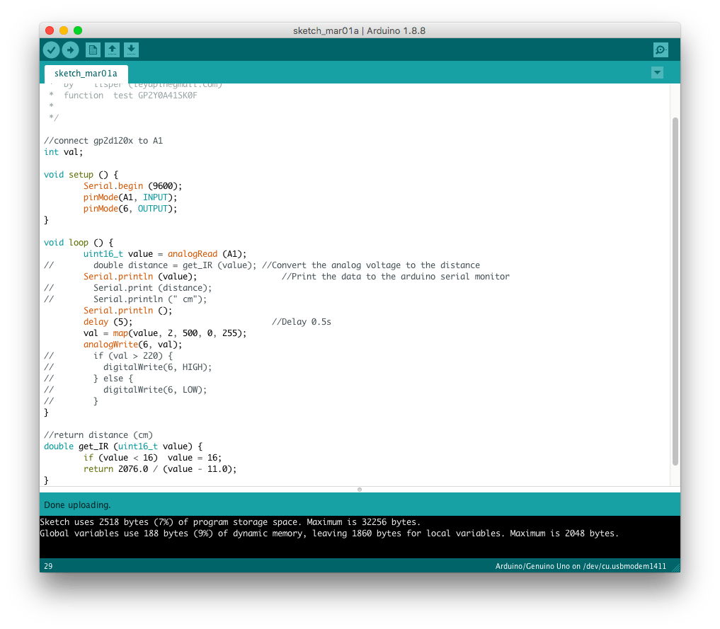
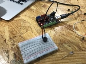
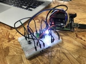
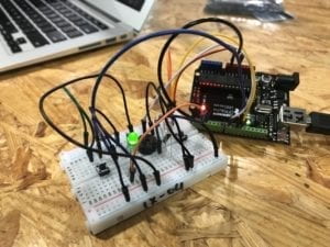
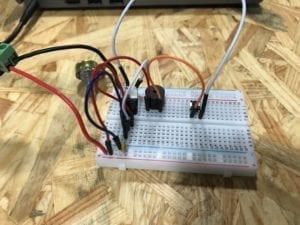
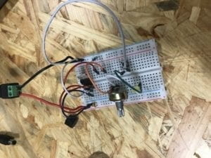
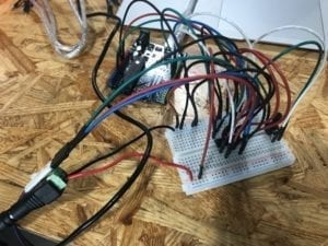
Step 2: Control rotation with a potentiometer

Building the circuit for step was easy, as we have had much experience in adding potentiometer to circuits. Then, we need to modify the example code to allow the potentiometer to control stepper motor’s rotation. First, I changed the number of steps to 200 to match our motor’s step. And then, I added the code to read potentiometer’s analog input and used “map()” function to change its range from 0-1023 to 0-255. After a few times of modification, it worked successfully.

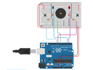
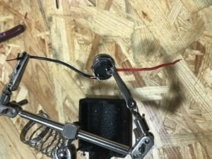
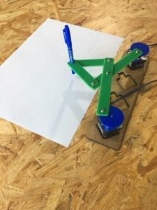
Step 3: Build a Drawing Machine!

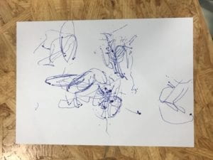
For step 3, I paired up with another student and built the drawing machine according to the picture. We met a few problems when trying to draw on papers. We found that the motors moved and vibrated greatly when they were rotating. We moved the motors closer to each other and it improved a little. Also its hard to control the pen with potentiometers, so we cannot actually “draw”. Below it’s the drawing we created.

Question 1:

I would like to build a machine that can help us pick up the food we ordered. It is really inconvenient for us to go downstairs to get our food, especially when we are on higher floors and elevators are crowded and slow. It is also inefficient for deliverymen to wait outside for people to come and sometimes people will even accidentally get the wrong order. So I want to build a machine that can bring our food to us. After the machine gets our food, we will receive a message, asking where we want the machine to go to and giving us the code to unlock the machine. Then it will wait there for a limited amount of time and we can get our food by entering the code. The actuators it needs are motor, wheels, and screen. And the design of it will be simple and small-sized so that it does not affect other people in the building.

Question 2:

Raffaello D’Andrea, Max Dean and Matt Donavan, The Table, 2001.

This installation is a robotic table that will automatically select viewers and move towards them, in order to “establish relationships” with them. It is interesting because the machine interacts with a human just as the way human interact with each other, which is also one of the major differences between this project and the drawing machine we built during recitation. The machine we build follows users’ instructions, while this table moves on its own. And I think the artist selected actuators according to the project’s goal and the functions they wanted to realize. For example, the table needs motors to move and it needs sensors to select viewers and detect their movements.

Group Research Project Reflection by Frances (Fan Yuan)

Instructor: Marcela

Definition:

Before taking this class, if someone asks me what interaction is, I would say it is one object reacting to another object’s orders or movements, but I have changed my mind now. Crawford put forward in his article The Art of Interactive Design that interaction is “a cyclic process in which two actors alternately listen, think, and speak”. And I think the most important part of this definition is “think”. It is pretty obvious that interaction must involve input and output, while “think” is more often ignored. So, my definition of interaction is a cyclic process in which two purposeful actors alternately receive, process and respond to actions or information.

Project that aligns with my definition:

Design I/O’s Mimic – Putting emotional machines within arm’s reach

This project creates a robotic arm that will react whenever someone moves closer or make gestures. It closely aligns with my definition because it has a range of dynamic moods and actions that is designed to respond to people’s different movements. The arm has its own “personality” and I think it is a great example of “thinking”.

https://www.creativeapplications.net/openframeworks/design-ios-mimic-putting-emotional-machines-within-arms-reach/

Project that doesn’t align with my definition:

A Wilderness Most Luminous – The Making of Micah Scott’s Forest

This project Forest is a giant tactile color mixer, and it seems to be interactive because people can engage with it by using the spinners to control its color. However, to some extent, it is similar to the refrigerator example that Crawford gives. It changes colors in accordance with the fixed instructions, which is just like turning on the lights when doors open.

https://www.creativeapplications.net/cinder/circle-forest/

Group project:

Our group project is called the Dream Catcher. It is a device that can record people’s dream when they are sleeping and show the dreams to them with a more detailed story after they wake up. And it is interactive according to our definition, because, first of all, it has between two actors (dreamer and the dream catcher) and it has input (recording dreams) and output (retelling dreams). More importantly, it expands our dreams into full narrative stories and pictures based on each person’s preferences. Instead of merely exporting what it receives, it enriches the content then responds.

Recitation 3. Sensors by Frances (Fan Yuan)

Instructor: Marcela

Circuit:

Components:

Arduino Uno, USB A to B cable, breadboard, LED, 220-ohm resistor, jumper cables

Infrared Distance Sensor: The sensor detects the straight-line distance by sending infrared light and it gives analog output.

Process:

First, we built the circuit below and ran it with the sample code to test the sensor’s output range. We moved the sensor back and forth from an object and looked at the serial monitor. We found out that when we moved the sensor further away the number gets smaller and the range is around 2 to 500.

Then, we decided to make a circuit with an LED, that when we get close to the sensor at a certain distance, the light will turn on. To adjust the value to LED’s range, we first add the map function to change the range to 0 to 255. Then, we add an if condition to set the light on when the value is bigger than a certain number. After we tested it, we found out that it reacted to moving really slow and it won’t turn off when we moved away. So, with the help from fellows, we made a few changes to the code. We add an else condition to give it instructions to turn off, change to delay time and adjust the determining value to 220, which performed well in our test.

After we complete that circuit, we made more changes. We replaced digitalWrite with analogWrite. In this way, the LED can change its brightness according to the distance the sensor detected.

References:

https://www.dfrobot.com/wiki/index.php/SHARP_GP2Y0A41SK0F_IR_ranger_sensor_(4-30cm)_SKU:SEN0143


Question 1:

We intended to assemble a circuit that could give signals, like turning on LED or making sounds, when an object moves close to the sensor. As for pragmatic purpose, it could be used at convenience stores as a part of automatic doors. When someone walks closer to the door, the sensor will sense him/her, and then the speaker plays melody and door opens.

Question 2:

People follow recipe or tutorial step by step and will know what to do. Code is similar, but only teaches computer instead of human. Computer follows the instructions written in the code line by line. It runs from the first line till the last, and will only move on to the next line when the previous one is finished or when it is given orders.

Question 3:

Computer influences our human behaviors in many ways. It changes the way we communicate and connects the world together. We have access to much more information, and it affects how we think and thus affects our behaviors. Moreover, it does a lot of computation work for us and frees us from repetitive tasks.

Recitation 2. Arduino Basics by Frances (Fan Yuan)

Instructor: Marcela

Circuit 1:

 Fade

Components:

Arduino Uno, USB A to B cable, breadboard, LED, 220-ohm resistor, jumper cables

Process:

The circuit is not very complicated, but at first, we made a mistake. Apart from connecting D9 with the LED, we also directly connected 5V power to the LED. So when we ran the program, LED lighted up but was not changing its brightness.

After we realized the problem, we took off the yellow wire and the LED started to fade. (The red wire is not needed in this circuit either.)

Circuit 2: toneMelody

Components:

Arduino Uno, USB A to B cable, breadboard, buzzer, jumper cables

Process:

The second circuit was built more smoothly. We moved the wire from D9 to D8 and replaced the resistor and LED with a buzzer. After uploading the code to Arduino, the buzzer played the melody successfully.

Circuit 3: Speed Game

Components:

Arduino Uno, USB A to B cable, breadboard, buzzer, 2 * LEDs, 2 * 220-ohm resistors, 2 * 10K ohm resistors, 2 * pushbuttons, jumper cables

Process:

The third circuit was much more complicated than the other two. There were a lot more components and wires, but we were provided with a picture of real circuit instead of a schematic, which made it easier to build. The first time we ran it, the game started but nothing happened as we keep pressing the button. Later we found out it was because both of the buttons were not connected to the circuit. So, we fixed it by making it connected exactly like the picture and it ran successfully.

Then, we built the fourth circuit with another group. To make four players compete together, firstly we changed the code. There were only two players in the original code, so we copied and pasted all the lines that had ‘1’ and ‘2’, and changed them into ‘3’ and ‘4’. Also, we changed the if conditions by adding player3, 4, and changed the corresponding pin numbers into other available pins. At last, we took off one breadboard and connected it to the other Arduino Uno’s pins with accordance to the code we just typed. The circuit was then completed.

Question 1:

Technology is everywhere in our daily life. From lights to phones and computers, technology is indispensable for us modern humans, and in my opinion, a lot of them are used by interactions. For example, we press switches to turn on lights, swipes cards to open the door, and with phones and laptops, we can do a lot more high-level interactions. With the development of artificial intelligence, we are now able to talk to phones like we do with human beings.

I also agree with the text Physical Computing that interactions require two or more actors and it includes “input, output, and processing”. For example, the circuit we built, it takes input like pressing buttons, processes by following the instructions we code, and gives output.

Question 2:

I would cover one of our school’s walls with all these LED lights, and make it an interactive wall. The wall can simulate natural environment and add more green to our school. Students can interact with it, like picking up leaves and ‘touching’ water. Moreover, for days that is raining or when the air quality is bad, the wall can simulate sunshine or stars. By standing in front of the wall, people can imagine to be in any environment they want and release their pressure.

Recitation 1. Electronics & Soldering by Frances (Fan Yuan)

Week 1: Recitation Documentation

Recitation 1: Electronics & Soldering

Instructor: Marcela

Circuit 1: Door Bell

Components:

  • Breadboard: This is where we plug in wires and connect all the components
  • LM7805 Voltage Regulator: It is used to maintain a constant voltage level
  • Buzzer: It is used as the speaker in the schematics, which will make sounds when the circuit is connected.
  • Push-Button Switch: To turn the speaker on and off.
  • 100 nF (0.1uF) Capacitor: It is parallel connected in the circuit. It blocks the direct current and let direct current to pass through the speaker, while it allows alternating current to pass and directly goes to the ground.
  • 12 volt power supply: Transfer 220V AC power and supply 12V power for the circuit.
  • Barrel Jack
  • Jumper Cables (Hook-up Wires)

Process:

At first, it took us some time to figure out how to provide 12V power supply, as the power source part is not clearly shown on the schematics. We found out at last that we need to connect our circuit to the socket and the equipment we had will transfer the electricity to 12V DC. And then we spent some time to get familiar with the breadboard, as we can’t see which parts are connected inside the board. After knowing exactly how current flows inside the board, things got easier. One last thing that we had trouble with was the ground. There are three components that is connected to it: switch, capacitor and the “GND” of the voltage regulator, so we got a little confused but we solved the problem eventually.

Circuit 2: Lamp

Components:

Breadboard, LM7805 Voltage Regulator, Push-Button Switch, 100 nF (0.1uF) Capacitor, Jumper Cables (Hook-up Wires)

  • 220 ohm Resistor: It decreases the current magnitude and protects the LED from burning.
  • Multimeter: It is used to distinguish the 220 and 10K ohm Resistors.
  • LED

Process:

Building the second circuit was easier because we already had the first one. We didn’t have to build it from the start, but only needed to take off the speaker and replace it with the 220 ohm resistor and LED light.

Circuit 3: Dimmable Lamp

Components:

Breadboard, LM7805 Voltage Regulator, Push-Button Switch, 100 nF (0.1uF) Capacitor, Jumper Cables (Hook-up Wires), 220 ohm Resistor, LED

  • 10K ohm Variable Resistor (Potentiometer): By changing the resistance of it, we can change the LED’s brightness.
  • Arcade Button

Process:

For the third circuit, we also built it based on the second one we already had. We added the 10K ohm variable resistor between the 220 ohm resistor and LED. After that, we went to the soldering station and soldered wires to an arcade button to make it connectable to the breadboard. Then, we went back to use it to replace the push button. While as we removed our completed circuit too early, we had to reconnect it again. And this time we accidentally plugged in the LED in the wrong direction, and it didn’t light up. This is a problem that we should pay more attention to next time.

Reading responses:

Question 1:

The circuits we built are to some extent similar to the refrigerator example in the article. The circuit could be considered interactive, as it listens (to the pressing button), thinks (with current flowing through the circuit in a certain direction), and speaks (by making sounds or lighting up). However, I also agree with the author that it is low-level interactivity, that it does not contain much meaning or thoughts with such interaction.

Question 2:

Interactive art could be created when it involves more thoughts and communications back and forth. In one of the projects that we saw in class, a plant owns its Twitter account by using Arduino and sensors to sense its states and send tweets online. This is a good example of interactivity. And I think the more important part about Interactive Art is not merely reacting to commands, but delivering information or expressing feelings.